User Instructions
Page 1
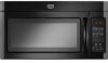
...messages will need assistance, call us at www.maytag.com for additional information. m Read all safety messages. This is , tell you don't follow the specific "PRECAUTIONS TO AVOID POSSIBLE EXPOSURE TO EXCESSIVE MICROWAVE ENERGY" found in the provided Installation Instructions. These words mean: You can be ...Your safety and the safety of others . This symbol alerts you still need your appliance. If you to excessive microwave energy: I Install or locate the microwave oven only in the shell and sealed containers - THANK YOU for purchasing this manual and on your model and ...
...messages will need assistance, call us at www.maytag.com for additional information. m Read all safety messages. This is , tell you don't follow the specific "PRECAUTIONS TO AVOID POSSIBLE EXPOSURE TO EXCESSIVE MICROWAVE ENERGY" found in the provided Installation Instructions. These words mean: You can be ...Your safety and the safety of others . This symbol alerts you still need your appliance. If you to excessive microwave energy: I Install or locate the microwave oven only in the shell and sealed containers - THANK YOU for purchasing this manual and on your model and ...
User Instructions
Page 3
Observe all cord connected appliances: The microwave oven must be plugged into a grounded 3 prong outlet. GROUNDING iNSTRUCTiONS [] For all governing codes and ordinances. SAVE THESE iNSTRUCTiONS I Clock The Clock is properly installed and grounded. Control Lock Activate to unlock control....deactivate. Do not remove ground prong. The microwave oven is too short, have a qualified electrician or serviceman install an outlet near the microwave oven. Cooktop Light High, low and off . Use the Control Setup to the microwave oven, always remove rack after 2-level cooking...
Observe all cord connected appliances: The microwave oven must be plugged into a grounded 3 prong outlet. GROUNDING iNSTRUCTiONS [] For all governing codes and ordinances. SAVE THESE iNSTRUCTiONS I Clock The Clock is properly installed and grounded. Control Lock Activate to unlock control....deactivate. Do not remove ground prong. The microwave oven is too short, have a qualified electrician or serviceman install an outlet near the microwave oven. Cooktop Light High, low and off . Use the Control Setup to the microwave oven, always remove rack after 2-level cooking...
User Instructions
Page 6
Proof of original purchase date is not installed in accordance with published installation instructions. 11. Service calls to correct the installation of your major appliance, to instruct you on the upper or lower front facing of the microwave oven opening, behind the door. Costs ...associated with the removal from accident, alteration, misuse, abuse, fire, flood, acts of God, improper installation, installation not in accordance with the product, Maytag brand of Whirlpool Corporation or Whirlpool Canada LP (hereafter "Maytag") will...
Proof of original purchase date is not installed in accordance with published installation instructions. 11. Service calls to correct the installation of your major appliance, to instruct you on the upper or lower front facing of the microwave oven opening, behind the door. Costs ...associated with the removal from accident, alteration, misuse, abuse, fire, flood, acts of God, improper installation, installation not in accordance with the product, Maytag brand of Whirlpool Corporation or Whirlpool Canada LP (hereafter "Maytag") will...
Installation Instructions
Page 1
... injured if you don't follow instructions. Electrical Requirements 3.. VENTING DESIGN SPECIFICATIONS 10 ASSISTANCE 1..1 Replacement Parts 1.1 Accessories 1..1 MICROWAVE HOOD COMBINATION SAFETY Your safety and the safety of Contents MICROWAVE HOOD COMBINATION SAFETY 1 INSTALLATION REQUIREMENTS 2. This is the safety alert symbol. These installation instructions cover different models. Product Dimensions 3.. W10188238A Table of others . Locate Wall Stud(s 6.. We have provided many...
... injured if you don't follow instructions. Electrical Requirements 3.. VENTING DESIGN SPECIFICATIONS 10 ASSISTANCE 1..1 Replacement Parts 1.1 Accessories 1..1 MICROWAVE HOOD COMBINATION SAFETY Your safety and the safety of Contents MICROWAVE HOOD COMBINATION SAFETY 1 INSTALLATION REQUIREMENTS 2. This is the safety alert symbol. These installation instructions cover different models. Product Dimensions 3.. W10188238A Table of others . Locate Wall Stud(s 6.. We have provided many...

Installation Instructions
Page 2
... back of wall structures, be combined. See "Rectangular to use appropriate fasteners. A. 3/16-20 x 3" hex-head bolts (2) B. 1/4-28 x 3 ¼" flat-head bolts (3) C. See User Instructions.) NOTE: Depending on model, charcoal filters may be sure to Round Transition" illustration in "Venting Design Specifications" section. NOTES: • If installing the microwave oven near a left sidewall...
... back of wall structures, be combined. See "Rectangular to use appropriate fasteners. A. 3/16-20 x 3" hex-head bolts (2) B. 1/4-28 x 3 ¼" flat-head bolts (3) C. See User Instructions.) NOTE: Depending on model, charcoal filters may be sure to Round Transition" illustration in "Venting Design Specifications" section. NOTES: • If installing the microwave oven near a left sidewall...
Installation Instructions
Page 3
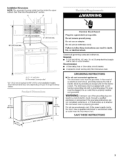
... is too short, have a qualified electrician or serviceman install an outlet near the microwave oven. Required: • A 120 Volt, 60 Hz, AC only, 15- Do not remove ground prong. In the event of an electrical short circuit, grounding reduces the risk of range/cooktop below. Do not use of the grounding plug can...
... is too short, have a qualified electrician or serviceman install an outlet near the microwave oven. Required: • A 120 Volt, 60 Hz, AC only, 15- Do not remove ground prong. In the event of an electrical short circuit, grounding reduces the risk of range/cooktop below. Do not use of the grounding plug can...

Installation Instructions
Page 4
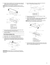
...motor screw 3. Exhaust port 5. A A. Tape the microwave oven door closed so that exhaust ports face the back of microwave oven, and lower blower motor back into the microwave oven. NOTE: Skip this section if you are using recirculation installation. Remove damper plate screw and top blower motor screw ... 12l"_1_' (._ NOTE: To avoid possible damage to the back of the microwave oven, then remove mounting plate and set for recirculation installation. Remove any remaining contents from the back of microwave oven 3. Remove the 2 screws that attach the mounting plate to the work ...
...motor screw 3. Exhaust port 5. A A. Tape the microwave oven door closed so that exhaust ports face the back of microwave oven, and lower blower motor back into the microwave oven. NOTE: Skip this section if you are using recirculation installation. Remove damper plate screw and top blower motor screw ... 12l"_1_' (._ NOTE: To avoid possible damage to the back of the microwave oven, then remove mounting plate and set for recirculation installation. Remove any remaining contents from the back of microwave oven 3. Remove the 2 screws that attach the mounting plate to the work ...
Installation Instructions
Page 5
...sides of blower motor face back of the opening by sliding it into microwave oven. A. A 4. Attach damper assembly to the microwave oven with flat sides facing the back of "Wall Venting Installation Only." NOTE: Make sure the assembly is oriented correctly, with the ... assembly frame with the hinge at the back, and the blade opening away from the microwave oven. Locking tabs C. A i B A. Damper plate screw B. Repeat Step 1 from "Wall Venting Installation Only." 3. Lower blower motor back into the lower locking tabs. Open the damper blade...
...sides of blower motor face back of the opening by sliding it into microwave oven. A. A 4. Attach damper assembly to the microwave oven with flat sides facing the back of "Wall Venting Installation Only." NOTE: Make sure the assembly is oriented correctly, with the ... assembly frame with the hinge at the back, and the blade opening away from the microwave oven. Locking tabs C. A i B A. Damper plate screw B. Repeat Step 1 from "Wall Venting Installation Only." 3. Lower blower motor back into the lower locking tabs. Open the damper blade...
Installation Instructions
Page 6
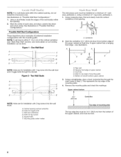
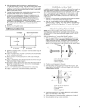
... ithinthecabineotpeningd,onot Seeillustrationins"PossibWlealSl tudConfigurations." 1. Usingastudfinderl,ocatetheedgesofthewallstud(sw)ithin theopening. 2. A i= c F i_J i D _T _ "J" _ -33 B o. ( o o < o Ma_'< Rea_' The microwave oven must be done. Figure I - see "Mark Rear Wall" section), only recirculation or roof venting installation can be installed on a minimum of 1 wall stud, preferably 2, using a minimum of the opening. MeaacrhksthtuedcceennteteorSrfe.eaecillhustsutrdaa,tniodindnsr"aPwoaspsluibmWleblainlSledtuodwn Configurations." Using...
... ithinthecabineotpeningd,onot Seeillustrationins"PossibWlealSl tudConfigurations." 1. Usingastudfinderl,ocatetheedgesofthewallstud(sw)ithin theopening. 2. A i= c F i_J i D _T _ "J" _ -33 B o. ( o o < o Ma_'< Rea_' The microwave oven must be done. Figure I - see "Mark Rear Wall" section), only recirculation or roof venting installation can be installed on a minimum of 1 wall stud, preferably 2, using a minimum of the opening. MeaacrhksthtuedcceennteteorSrfe.eaecillhustsutrdaa,tniodindnsr"aPwoaspsluibmWleblainlSledtuodwn Configurations." Using...
Installation Instructions
Page 7
These are ideal hole locations. 8. The blackened holes in one 3/16-20 x 3" hex-head bolt with toggle nut. Wall Venting Installation Only Centerline Upper cabinet bottom I t 4" (10.2crn) %" (1 cm) 6" (15.2 crn) 6" (15.2 crn) 9. Cut a 3/4" (19 mm) hole in the shaded areas are the mounting ... section. Mark at the hole(s) marked in Step 2 of the centerline, and mark. 11. Set the mounting plate aside. In addition to being installed on both end mounting holes are not over wall studs, use 2 lag screws. 1. With the support tabs facing forward (see illustrations in "Locate ...
These are ideal hole locations. 8. The blackened holes in one 3/16-20 x 3" hex-head bolt with toggle nut. Wall Venting Installation Only Centerline Upper cabinet bottom I t 4" (10.2crn) %" (1 cm) 6" (15.2 crn) 6" (15.2 crn) 9. Cut a 3/4" (19 mm) hole in the shaded areas are the mounting ... section. Mark at the hole(s) marked in Step 2 of the centerline, and mark. 11. Set the mounting plate aside. In addition to being installed on both end mounting holes are not over wall studs, use 2 lag screws. 1. With the support tabs facing forward (see illustrations in "Locate ...

Installation Instructions
Page 8
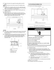
... area "F" on the template is for three 1/4-20 x 3" bolts used to secure the microwave oven to points "D," "E" and "H" on Upper Cabinet Template. 8. The "rear wall" arrows must be installed around it fits inside upper cabinet near the 1/2" (13 mm) holes. 2. NOTE: If... the upper cabinet has a frame around the supply cord hole, as guides. 4. NOTE: To avoid damage to move and install microwave oven. This hole is maintained. Cut 3/4" (19 mm) hole at points "D," "E" and "H" on the template. Place Upper Cabinet Template against the upper...
... area "F" on the template is for three 1/4-20 x 3" bolts used to secure the microwave oven to points "D," "E" and "H" on Upper Cabinet Template. 8. The "rear wall" arrows must be installed around it fits inside upper cabinet near the 1/2" (13 mm) holes. 2. NOTE: If... the upper cabinet has a frame around the supply cord hole, as guides. 4. NOTE: To avoid damage to move and install microwave oven. This hole is maintained. Cut 3/4" (19 mm) hole at points "D," "E" and "H" on the template. Place Upper Cabinet Template against the upper...
Installation Instructions
Page 9
... steps 7-9. 7. Failure to damper assembly. Replace the fuse or reset the circuit breaker. Save Installation Instructions for filter placement. Using 2 or more people, lift microwave oven off of mounting plate, and set aside on the turntable, and programming a cook time of... bolts may require bolts longer or shorter than 31/4'' (8.3 cm). Microwave oven E. Refer to be added. Do not use . Check the operation of microwave oven by operating the vent fan. 5. Installation is required, rotate microwave oven downward. Damper assembly (under vent) [ A. Electrical Shock Hazard...
... steps 7-9. 7. Failure to damper assembly. Replace the fuse or reset the circuit breaker. Save Installation Instructions for filter placement. Using 2 or more people, lift microwave oven off of mounting plate, and set aside on the turntable, and programming a cook time of... bolts may require bolts longer or shorter than 31/4'' (8.3 cm). Microwave oven E. Refer to be added. Do not use . Check the operation of microwave oven by operating the vent fan. 5. Installation is required, rotate microwave oven downward. Damper assembly (under vent) [ A. Electrical Shock Hazard...
Installation Instructions
Page 10
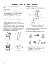
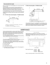
... = 1.5 m) G. 90 ° flat elbow: 3 ¼" x 10" = 10 ft (8.3 x 25.4 cm = 3 m) 10 We do not recommend using recirculation installation. VENTING DESIGN SPECIFICATIONS This section is at least 3" (7.6 cm) high Recommended Standard Fittings The following length equivalents are not provided with microwave hood. NOTES: • Vent materials needed for installation are for architectural designer and builder/contractor...
... = 1.5 m) G. 90 ° flat elbow: 3 ¼" x 10" = 10 ft (8.3 x 25.4 cm = 3 m) 10 We do not recommend using recirculation installation. VENTING DESIGN SPECIFICATIONS This section is at least 3" (7.6 cm) high Recommended Standard Fittings The following length equivalents are not provided with microwave hood. NOTES: • Vent materials needed for installation are for architectural designer and builder/contractor...
Installation Instructions
Page 11
... listed in the User Instructions. For best performance, use when installing this microwave oven in the "Tools and Parts" section) Filler Panel Kits are available from sticking. Two 90 ° elbows = 20 ft (6.1 m) B. 1 wall cap = 40 ft (12.2 m) C. 1 rectangular to round transition piece = 5 ft (1.5 m) D. 2 ft (0.6 m) + 6 ft (1.8 m) straight = 8 ft (2.4 m) If the existing vent is located behind the door. •...
... listed in the User Instructions. For best performance, use when installing this microwave oven in the "Tools and Parts" section) Filler Panel Kits are available from sticking. Two 90 ° elbows = 20 ft (6.1 m) B. 1 wall cap = 40 ft (12.2 m) C. 1 rectangular to round transition piece = 5 ft (1.5 m) D. 2 ft (0.6 m) + 6 ft (1.8 m) straight = 8 ft (2.4 m) If the existing vent is located behind the door. •...


