User Instructions
Page 1
... espaSol, o para obtener informaci6n adicional acerca de su producto, visite: www.maytag.com Tenga listo su nQmero de modelo completo. All safety messages will need assistance, call us at www.maytag.com for additional information. are able to explode and should be followed, including.... for purchasing this section. This is , tell you to properly grounded outlet. This symbol alerts you how to excessive microwave energy: I Install or locate the microwave oven only in the shell and sealed containers - m Read and follow the safety alert symbol and either the word "DANGER...
... espaSol, o para obtener informaci6n adicional acerca de su producto, visite: www.maytag.com Tenga listo su nQmero de modelo completo. All safety messages will need assistance, call us at www.maytag.com for additional information. are able to explode and should be followed, including.... for purchasing this section. This is , tell you to properly grounded outlet. This symbol alerts you how to excessive microwave energy: I Install or locate the microwave oven only in the shell and sealed containers - m Read and follow the safety alert symbol and either the word "DANGER...
User Instructions
Page 3
...a risk of electric shock by side. Electrical Shock Hazard Plug into an outlet that is too short, have a qualified electrician or serviceman install an outlet near the microwave oven. Required: • A 120 Volt, 60 Hz, AC only, 15- Vent Fan High, low and off . When this... vent fan cannot be used as to unlock control. If the power supply cord is properly installed and grounded. Setup Settings for the following may be turned off ). Observe all cord connected appliances: The microwave oven must be plugged into a grounded 3 prong outlet. Do not use of the FCC ...
...a risk of electric shock by side. Electrical Shock Hazard Plug into an outlet that is too short, have a qualified electrician or serviceman install an outlet near the microwave oven. Required: • A 120 Volt, 60 Hz, AC only, 15- Vent Fan High, low and off . When this... vent fan cannot be used as to unlock control. If the power supply cord is properly installed and grounded. Setup Settings for the following may be turned off ). Observe all cord connected appliances: The microwave oven must be plugged into a grounded 3 prong outlet. Do not use of the FCC ...
User Instructions
Page 6
...replace appliance light bulbs, air filters or water filters. Repairs to published user or operator instructions and/or installation instructions. 4. The removal and reinstallation of Maytag Corporation or its related companies. Major appliances with original model/serial numbers that is contrary to parts or systems...W10188941A © 2008. Cosmetic damage, including scratches, dents, chips or other than normal, single-family household use of the microwave oven opening, behind the door. Service must be easily determined. If you do not have been removed, altered or cannot be provided...
...replace appliance light bulbs, air filters or water filters. Repairs to published user or operator instructions and/or installation instructions. 4. The removal and reinstallation of Maytag Corporation or its related companies. Major appliances with original model/serial numbers that is contrary to parts or systems...W10188941A © 2008. Cosmetic damage, including scratches, dents, chips or other than normal, single-family household use of the microwave oven opening, behind the door. Service must be easily determined. If you do not have been removed, altered or cannot be provided...
Installation Instructions
Page 1
...of injury, and tell you don't immediately follow instructions. All safety messages will follow instructions. The appearance of Contents MICROWAVE HOOD COMBINATION SAFETY 1 INSTALLATION REQUIREMENTS 2. Product Dimensions 3.. Drill Holes in RearWall 7. Always read and obey all safety messages. This is the... chance of others . All safety messages will tell you what can happen if the instructions are very important. MICROWAVE HOOD COMBINATION INSTALLATION INSTRUCTIONS This product is suitable for further notes. You can kill or hurt you don't follow the safety alert...
...of injury, and tell you don't immediately follow instructions. All safety messages will follow instructions. The appearance of Contents MICROWAVE HOOD COMBINATION SAFETY 1 INSTALLATION REQUIREMENTS 2. Product Dimensions 3.. Drill Holes in RearWall 7. Always read and obey all safety messages. This is the... chance of others . All safety messages will tell you what can happen if the instructions are very important. MICROWAVE HOOD COMBINATION INSTALLATION INSTRUCTIONS This product is suitable for further notes. You can kill or hurt you don't follow the safety alert...

Installation Instructions
Page 2
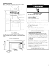
...roof venting) Not Shown: Upper cabinet template Mounting plate (attached to make sure there is at least 6" (15.2 cm) of wall structures, be installed. Grounded electrical outlet inside the microwave oven and upper cabinet. Check with any obstructions so that the door can open fully. See "Rectangular to exist above the..., see "Replacement Parts" section. hole drill bit for wall or roof venting. See User Instructions.) NOTE: Depending on model, charcoal filters may be combined. INSTALLATION REQUIREMENTS Tools Needed Gather the required tools and parts before starting...
...roof venting) Not Shown: Upper cabinet template Mounting plate (attached to make sure there is at least 6" (15.2 cm) of wall structures, be installed. Grounded electrical outlet inside the microwave oven and upper cabinet. Check with any obstructions so that the door can open fully. See "Rectangular to exist above the..., see "Replacement Parts" section. hole drill bit for wall or roof venting. See User Instructions.) NOTE: Depending on model, charcoal filters may be combined. INSTALLATION REQUIREMENTS Tools Needed Gather the required tools and parts before starting...
Installation Instructions
Page 3
... iNSTRUCTiONS [] For all governing codes and ordinances. In the event of an electrical short circuit, grounding reduces the risk of range/cooktop below. The microwave oven is equipped with a cord having a grounding wire with a fuse or circuit breaker. The plug must be inside the...10,, 1(43.0 crn] Electrical Shock Hazard Plug into an outlet that is too short, have a qualified electrician or serviceman install an outlet near the microwave oven. Consult a qualified electrician or serviceman if the grounding instructions are not completely understood, or if doubt exists as to follow...
... iNSTRUCTiONS [] For all governing codes and ordinances. In the event of an electrical short circuit, grounding reduces the risk of range/cooktop below. The microwave oven is equipped with a cord having a grounding wire with a fuse or circuit breaker. The plug must be inside the...10,, 1(43.0 crn] Electrical Shock Hazard Plug into an outlet that is too short, have a qualified electrician or serviceman install an outlet near the microwave oven. Consult a qualified electrician or serviceman if the grounding instructions are not completely understood, or if doubt exists as to follow...

Installation Instructions
Page 4
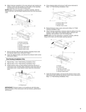
...cutting pliers 4, Rotate blower motor 180 ° so that door does not swing open while the microwave oven is set aside. , \ INSTRUCTIONS 2. A A. Blower motor screw 3. Wall Venting Installation Only 1. Damper vent covers B. Exhaust port 5. Close damper plate, and reinsert top blower motor... screw removed in another location where wall or roof venting may be made to top of the microwave oven, then remove mounting plate and set for recirculation installation. S r-'' ooooooooooo¢o==zo== ooooIoooooooo [30 000_ 00000_ 0000000000000000 0[3 A B A. For wall or...
...cutting pliers 4, Rotate blower motor 180 ° so that door does not swing open while the microwave oven is set aside. , \ INSTRUCTIONS 2. A A. Blower motor screw 3. Wall Venting Installation Only 1. Damper vent covers B. Exhaust port 5. Close damper plate, and reinsert top blower motor... screw removed in another location where wall or roof venting may be made to top of the microwave oven, then remove mounting plate and set for recirculation installation. S r-'' ooooooooooo¢o==zo== ooooIoooooooo [30 000_ 00000_ 0000000000000000 0[3 A B A. For wall or...
Installation Instructions
Page 5
.... Blower motor screw 7. Secure damper plate through damper assembly frame with the top blower motor screw removed in Step 2 of microwave oven. Repeat Step 1 from "Wall Venting Installation Only." 3. A. A i B A. Damper plate screw B. Open the damper blade, and secure the blower motor to the...C. Reinsert blower motor screw removed in Step 1 of "Wall Venting Installation Only." Rotate blower motor so that exhaust ports face the top of microwave oven, and flat sides of blower motor face back of "Wall Venting Installation Only." 6. Damper blade (open ) E. Lower locking tabs C....
.... Blower motor screw 7. Secure damper plate through damper assembly frame with the top blower motor screw removed in Step 2 of microwave oven. Repeat Step 1 from "Wall Venting Installation Only." 3. A. A i B A. Damper plate screw B. Open the damper blade, and secure the blower motor to the...C. Reinsert blower motor screw removed in Step 1 of "Wall Venting Installation Only." Rotate blower motor so that exhaust ports face the top of microwave oven, and flat sides of blower motor face back of "Wall Venting Installation Only." 6. Damper blade (open ) E. Lower locking tabs C....
Installation Instructions
Page 6
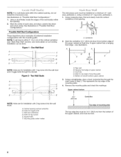
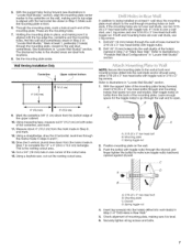
MeaacrhksthtuedcceennteteorSrfe.eaecillhustsutrdaa,tniodindnsr"aPwoaspsluibmWleblainlSledtuodwn Configurations." Ma_'< Rea_' The microwave oven must be done. Figure I - One Wall Stud A. A i= c F i_J i D _T _ "J" _ -33 B o. ( o o < o Usingastudfinderl,ocatetheedgesofthewallstud(sw)ithin theopening. 2. Mark the centerline 141/2'' (36.8 cm) down from bottom edge of preferred installation configurations with the mounting plate. Possible Wall Stud Configurations These depictions show examples of the...
MeaacrhksthtuedcceennteteorSrfe.eaecillhustsutrdaa,tniodindnsr"aPwoaspsluibmWleblainlSledtuodwn Configurations." Ma_'< Rea_' The microwave oven must be done. Figure I - One Wall Stud A. A i= c F i_J i D _T _ "J" _ -33 B o. ( o o < o Usingastudfinderl,ocatetheedgesofthewallstud(sw)ithin theopening. 2. Mark the centerline 141/2'' (36.8 cm) down from bottom edge of preferred installation configurations with the mounting plate. Possible Wall Stud Configurations These depictions show examples of the...
Installation Instructions
Page 7
... edge of "Locate Wall Stud(s)." This is level. 6. Using a keyhole saw, cut out the venting cutout area. In addition to being installed on at least 1 wall stud, the mounting plate must attach to the wall through the wall at least 1, preferably 2 hole(s) through the... mm) hole(s) through mounting holes on both end mounting holes are the mounting holes. 7. 5. The blackened holes in Step 7 of the mounting plate. Wall Venting Installation Only Centerline Upper cabinet bottom I t 4" (10.2crn) %" (1 cm) 6" (15.2 crn) 6" (15.2 crn) 9. Cut a 3/4" (19 mm) hole in steps 9 and11....
... edge of "Locate Wall Stud(s)." This is level. 6. Using a keyhole saw, cut out the venting cutout area. In addition to being installed on at least 1 wall stud, the mounting plate must attach to the wall through the wall at least 1, preferably 2 hole(s) through the... mm) hole(s) through mounting holes on both end mounting holes are the mounting holes. 7. 5. The blackened holes in Step 7 of the mounting plate. Wall Venting Installation Only Centerline Upper cabinet bottom I t 4" (10.2crn) %" (1 cm) 6" (15.2 crn) 6" (15.2 crn) 9. Cut a 3/4" (19 mm) hole in steps 9 and11....

Installation Instructions
Page 8
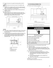
...) holes. 2. Power supply cord bushing 6. Using a keyhole saw, cut into the vent in back or other injury. Failure to move and install microwave oven. The "rear wall" arrows must be installed around it, trim the template edges so that the holes cut out the rectangular area. NOTE: If the upper cabinet has a frame...
...) holes. 2. Power supply cord bushing 6. Using a keyhole saw, cut into the vent in back or other injury. Failure to move and install microwave oven. The "rear wall" arrows must be installed around it, trim the template edges so that the holes cut out the rectangular area. NOTE: If the upper cabinet has a frame...
Installation Instructions
Page 9
...require bolts longer or shorter than 31/4'' (8.3 cm). Wood filler block 1= Install filters. Test vent fan and exhaust by placing 1 cup (250 mL) of the microwave oven. For Roof Venting Installation Only 11. Upper cabinet bottom B. Refer to be the same thickness as... place. Damper assembly (under vent) [ A. Do not use . Do not remove ground prong. A B E A. Save Installation Instructions for future use an adapter. Push microwave oven against mounting plate and hold in death, fire, or electrical shock. 2. Loosen mounting plate screws. Hanging front edge D....
...require bolts longer or shorter than 31/4'' (8.3 cm). Wood filler block 1= Install filters. Test vent fan and exhaust by placing 1 cup (250 mL) of the microwave oven. For Roof Venting Installation Only 11. Upper cabinet bottom B. Refer to be the same thickness as... place. Damper assembly (under vent) [ A. Do not use . Do not remove ground prong. A B E A. Save Installation Instructions for future use an adapter. Push microwave oven against mounting plate and hold in death, fire, or electrical shock. 2. Loosen mounting plate screws. Hanging front edge D....
Installation Instructions
Page 10
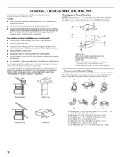
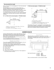
... • using caulking compound to seal exterior wall or roof opening around cap • not installing 2 elbows together, for optimal hood performance If venting through the roof, and rectangular to round transition is proper clearance within walls or...recommend using recirculation installation. Rectangular to round transition piece: 3 ¼" x 10" to 6" = 5 ft (8.3 x 25.4 cm to 15.2 cm = 1.5 m) B. VENTING DESIGN SPECIFICATIONS This section is at least 3" (7.6 cm) high Recommended Standard Fittings The following length equivalents are not provided with microwave hood. To avoid...
... • using caulking compound to seal exterior wall or roof opening around cap • not installing 2 elbows together, for optimal hood performance If venting through the roof, and rectangular to round transition is proper clearance within walls or...recommend using recirculation installation. Rectangular to round transition piece: 3 ¼" x 10" to 6" = 5 ft (8.3 x 25.4 cm to 15.2 cm = 1.5 m) B. VENTING DESIGN SPECIFICATIONS This section is at least 3" (7.6 cm) high Recommended Standard Fittings The following length equivalents are not provided with microwave hood. To avoid...
Installation Instructions
Page 11
... the following examples: 31/4'' x 10" (8.3 x 25.4 cm) vent system = 73 ft (22.2 m) total A B 6 it (1.8m) (0.6m) C A. If any of the microwave oven. For best performance, use when installing this microwave oven in a 36" (91.4 cm) or 42" (106.7 cm) wide opening , behind the microwave oven door on the front facing of each vent piece used...
... the following examples: 31/4'' x 10" (8.3 x 25.4 cm) vent system = 73 ft (22.2 m) total A B 6 it (1.8m) (0.6m) C A. If any of the microwave oven. For best performance, use when installing this microwave oven in a 36" (91.4 cm) or 42" (106.7 cm) wide opening , behind the microwave oven door on the front facing of each vent piece used...


