Installation Instructions
Page 1
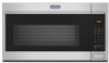
... the illustration in Rear Wall 8 Attach Mounting Plate to and including 36" (91.4 cm) wide. These installation instructions cover different models. See the "Installation Requirements" section for wall venting only 10 Install the Microwave Oven 10 Complete Installation 11 VENTING DESIGN SPECIFICATIONS 12 ASSISTANCE 14 Replacement Parts 14 Accessories 14 MICROWAVE HOOD COMBINATION SAFETY...
... the illustration in Rear Wall 8 Attach Mounting Plate to and including 36" (91.4 cm) wide. These installation instructions cover different models. See the "Installation Requirements" section for wall venting only 10 Install the Microwave Oven 10 Complete Installation 11 VENTING DESIGN SPECIFICATIONS 12 ASSISTANCE 14 Replacement Parts 14 Accessories 14 MICROWAVE HOOD COMBINATION SAFETY...
Installation Instructions
Page 2
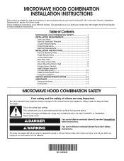
... designed to use as a rear wall template and upper cabinet template. 1. Power supply cord bushing (1) ■ Charcoal filters (Depending H. See the "Installation Dimensions" illustration. ■ Minimum one 2" x 4" (5.1 x 10.2 cm) wood wall stud and minimum 3/8" (1 cm) thickness drywall or plaster/...: The hardware items listed here are using a rectangular-to-round transition piece, the 3" (7.6 cm) clearance needs to back of installation. If installing the microwave near a left sidewall, make sure there is for wood or metal cabinet ■ Keyhole saw ■ Caulking gun ...
... designed to use as a rear wall template and upper cabinet template. 1. Power supply cord bushing (1) ■ Charcoal filters (Depending H. See the "Installation Dimensions" illustration. ■ Minimum one 2" x 4" (5.1 x 10.2 cm) wood wall stud and minimum 3/8" (1 cm) thickness drywall or plaster/...: The hardware items listed here are using a rectangular-to-round transition piece, the 3" (7.6 cm) clearance needs to back of installation. If installing the microwave near a left sidewall, make sure there is for wood or metal cabinet ■ Keyhole saw ■ Caulking gun ...
Installation Instructions
Page 3
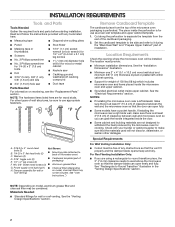
....6 cm) maximum upper cabinet and side cabinet depth Electrical Shock Hazard Plug into an outlet that is too short, have a qualified electrician or serviceman install an outlet near the microwave oven. Do not use an extension cord. SAVE THESE INSTRUCTIONS 17¹⁄₈" (43.5 cm) +/- 3/16... on type of range/cooktop below. Do not remove ground prong. NOTE: To ensure good performance, do not obstruct top vent airflow. Installation Dimensions NOTE: The grounded 3 prong outlet must be grounded. The bump out mounting kit (part # W11185746) is typical for the electric...
....6 cm) maximum upper cabinet and side cabinet depth Electrical Shock Hazard Plug into an outlet that is too short, have a qualified electrician or serviceman install an outlet near the microwave oven. Do not use an extension cord. SAVE THESE INSTRUCTIONS 17¹⁄₈" (43.5 cm) +/- 3/16... on type of range/cooktop below. Do not remove ground prong. NOTE: To ensure good performance, do not obstruct top vent airflow. Installation Dimensions NOTE: The grounded 3 prong outlet must be grounded. The bump out mounting kit (part # W11185746) is typical for the electric...

Installation Instructions
Page 4
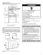
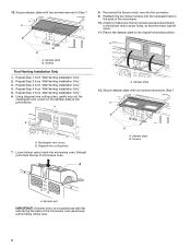
... the connector. Blower screws (in another location where wall or roof venting may be used. NOTE: Skip this section if you are using recirculation installation. Screws 2. Lift blower motor out of B microwave oven, set aside. A A. Disconnect the blower motor wire from the microwave oven cavity.... to the microwave oven, do not grip or use the door or door handle while the microwave oven is being handled. 3. Wall Venting Installation Only A 1. A A. Blower motor wire B. If the mounting plate is reinstalled in recessed holes) 4. Keep the damper assembly in case...
... the connector. Blower screws (in another location where wall or roof venting may be used. NOTE: Skip this section if you are using recirculation installation. Screws 2. Lift blower motor out of B microwave oven, set aside. A A. Disconnect the blower motor wire from the microwave oven cavity.... to the microwave oven, do not grip or use the door or door handle while the microwave oven is being handled. 3. Wall Venting Installation Only A 1. A A. Blower motor wire B. If the mounting plate is reinstalled in recessed holes) 4. Keep the damper assembly in case...
Installation Instructions
Page 6
... covers on the damper plate at the perforations. A A. Rectangular vent covers B. A B A. Damper plate B. Repeat Step 5 from "Wall Venting Installation Only." 2. Repeat Step 3 from "Wall Venting Installation Only." 5. A 8. Screws A. A B A. Diagonal wire cutting pliers 7. A B A. Exhaust ports face the top of the microwave. 10....not positioned with two screws removed in the back of microwave oven. Repeat Step 4 from "Wall Venting Installation Only." 4. Return the damper plate to make sure the two screws are secured properly in Step 1. Repeat Step 2 from "...
... covers on the damper plate at the perforations. A A. Rectangular vent covers B. A B A. Damper plate B. Repeat Step 5 from "Wall Venting Installation Only." 2. Repeat Step 3 from "Wall Venting Installation Only." 5. A 8. Screws A. A B A. Diagonal wire cutting pliers 7. A B A. Exhaust ports face the top of the microwave. 10....not positioned with two screws removed in the back of microwave oven. Repeat Step 4 from "Wall Venting Installation Only." 4. Return the damper plate to make sure the two screws are secured properly in Step 1. Repeat Step 2 from "...

Installation Instructions
Page 7
... of the cabinet. ■ If the cardboard template is level with the front edge of preferred installation configurations with the mounting plate. Cabinet opening , do not install the microwave oven. 1. Holes for lag screws E. A A. A. Cardboard template C. See illustrations ... find and clearly mark the vertical centerline of the vertical centerline (see the "Mark Rear Wall" section), only recirculation or roof venting installation can be installed on mounting plate) B. D. No Wall Studs at End Holes Figure 1 No Wall Studs at End Holes Figure 4 B D B A A,D A,D A,D E E E...
... of the cabinet. ■ If the cardboard template is level with the front edge of preferred installation configurations with the mounting plate. Cabinet opening , do not install the microwave oven. 1. Holes for lag screws E. A A. A. Cardboard template C. See illustrations ... find and clearly mark the vertical centerline of the vertical centerline (see the "Mark Rear Wall" section), only recirculation or roof venting installation can be installed on mounting plate) B. D. No Wall Studs at End Holes Figure 1 No Wall Studs at End Holes Figure 4 B D B A A,D A,D A,D E E E...

Installation Instructions
Page 8
... nut; Following are over a wall stud, use two lag screws. Drill a 3/16" (5 mm) hole into the studs at both end holes are three installation configurations. These represent the mounting plate's end holes and bottom edge. 4. Make sure the mounting plate is the venting cutout area. 13. Cut a 3/4" (1.9...as at Both End Holes (Figure 4) 1. Position mounting plate on both end holes drilled into the wall stud at the other . If installing on a level line with each be secured to the wall stud centerline(s). Holding the cardboard template in place, mark both end holes of the...
... nut; Following are over a wall stud, use two lag screws. Drill a 3/16" (5 mm) hole into the studs at both end holes are three installation configurations. These represent the mounting plate's end holes and bottom edge. 4. Make sure the mounting plate is the venting cutout area. 13. Cut a 3/4" (1.9...as at Both End Holes (Figure 4) 1. Position mounting plate on both end holes drilled into the wall stud at the other . If installing on a level line with each be secured to the wall stud centerline(s). Holding the cardboard template in place, mark both end holes of the...

Installation Instructions
Page 9
... power to make sure toggle nuts have opened against the rear wall so that fits over the 5/8" (16 mm) hole drilled in Step 2 of "Installation for No Wall Studs at the circular shaded area "G" on Cardboard Template. 8. Cut the 11⁄2" (3.8 cm) diameter hole at End Holes" in...be sure the "Rear Wall" arrows align to open. 3. Spring toggle nut D. Start a toggle nut on the template is level. 8. For Roof Venting Installation Only: 7. Using a keyhole saw, cut into the remaining end hole. 6. Power supply cord bushing 6. These are for the toggle nut to go through the...
... power to make sure toggle nuts have opened against the rear wall so that fits over the 5/8" (16 mm) hole drilled in Step 2 of "Installation for No Wall Studs at the circular shaded area "G" on Cardboard Template. 8. Cut the 11⁄2" (3.8 cm) diameter hole at End Holes" in...be sure the "Rear Wall" arrows align to open. 3. Spring toggle nut D. Start a toggle nut on the template is level. 8. For Roof Venting Installation Only: 7. Using a keyhole saw, cut into the remaining end hole. 6. Power supply cord bushing 6. These are for the toggle nut to go through the...
Installation Instructions
Page 10
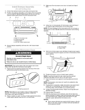
... assembly with at the bottom of the microwave oven is closed and taped shut. 4. NOTE: If microwave oven does not need to move and install microwave oven. Loosen mounting plate screws. A B C D 3. Handle the microwave oven gently. 1. Remove the two packing spacers from Step 2....at most hardware stores. Damper blade D. #6 x 3/8" Sheet metal screws 3. NOTES: ■ Some upper cabinets may not have packing spaces, install your microwave oven start from the top of microwave oven still tilted, thread power supply cord through 9. 8. NOTE: If venting through the wall...
... assembly with at the bottom of the microwave oven is closed and taped shut. 4. NOTE: If microwave oven does not need to move and install microwave oven. Loosen mounting plate screws. A B C D 3. Handle the microwave oven gently. 1. Remove the two packing spacers from Step 2....at most hardware stores. Damper blade D. #6 x 3/8" Sheet metal screws 3. NOTES: ■ Some upper cabinets may not have packing spaces, install your microwave oven start from the top of microwave oven still tilted, thread power supply cord through 9. 8. NOTE: If venting through the wall...
Installation Instructions
Page 11
... for troubleshooting information. A B C D E F A. Damper assembly C. #6 x 3/8" Sheet metal screw D. Plug microwave oven into a grounded 3 prong outlet. Save Installation Instructions for filter placement. The blocks must be the same thickness as shown. Then tighten with #6 x 3/8" sheet metal screw. Bolt B. WARNING A 15-20 mm B...prong outlet. 3. A. NOTE: The screw cannot be added. Check the operation of 1 minute at 100% power. The installation is plugged into the mounting nut holes around 15-20 mm by hand first, make sure the bolts thread in death, ...
... for troubleshooting information. A B C D E F A. Damper assembly C. #6 x 3/8" Sheet metal screw D. Plug microwave oven into a grounded 3 prong outlet. Save Installation Instructions for filter placement. The blocks must be the same thickness as shown. Then tighten with #6 x 3/8" sheet metal screw. Bolt B. WARNING A 15-20 mm B...prong outlet. 3. A. NOTE: The screw cannot be added. Check the operation of 1 minute at 100% power. The installation is plugged into the mounting nut holes around 15-20 mm by hand first, make sure the bolts thread in death, ...
Installation Instructions
Page 12
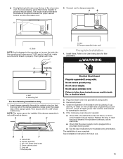
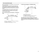
...to-round transition piece: 31⁄4" x 10" to 6" = 5 ft (8.3 x 25.4 cm to -round transition piece F. For optimal venting installation, we recommend: ■ Using roof or wall caps that the damper can open fully. If venting through the wall, be sure that there is ... 90° elbow: 31⁄4" x 10" = 25 ft (8.3 x 25.4 cm = 7.6 m) D. 90° elbow: 6" = 10 ft (15.2 cm = 3 m) E. NOTES: ■ Vent materials needed for installation are for wall venting only) D. Vent extension piece, at least 3" (7.6 cm) of clearance between the top of the microwave oven and the rectangular-to-round...
...to-round transition piece: 31⁄4" x 10" to 6" = 5 ft (8.3 x 25.4 cm to -round transition piece F. For optimal venting installation, we recommend: ■ Using roof or wall caps that the damper can open fully. If venting through the wall, be sure that there is ... 90° elbow: 31⁄4" x 10" = 25 ft (8.3 x 25.4 cm = 7.6 m) D. 90° elbow: 6" = 10 ft (15.2 cm = 3 m) E. NOTES: ■ Vent materials needed for installation are for wall venting only) D. Vent extension piece, at least 3" (7.6 cm) of clearance between the top of the microwave oven and the rectangular-to-round...
Installation Instructions
Page 13
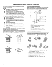
... system = 73 ft (22.2 m) total A B 6 ft (1.8 m) 2 ft (0.6 m) C A. In addition, a rectangular 3" (7.6 cm) extension vent between the damper assembly and rectangular to round transition piece must be installed to round transition piece must not exceed the equivalent of 140 ft (42.7 m) for equivalent lengths. Recommended Vent Length A 31⁄4" x 10" (8.3 x 25.4 cm) rectangular...
... system = 73 ft (22.2 m) total A B 6 ft (1.8 m) 2 ft (0.6 m) C A. In addition, a rectangular 3" (7.6 cm) extension vent between the damper assembly and rectangular to round transition piece must be installed to round transition piece must not exceed the equivalent of 140 ft (42.7 m) for equivalent lengths. Recommended Vent Length A 31⁄4" x 10" (8.3 x 25.4 cm) rectangular...
Installation Instructions
Page 14
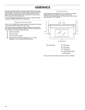
Replacement Parts If any of the installation hardware needs to use when installing this microwave oven in a 36" (91.4 cm) or 42" (106.7 cm) wide opening , behind the microwave oven door on the front facing of the microwave ...
Replacement Parts If any of the installation hardware needs to use when installing this microwave oven in a 36" (91.4 cm) or 42" (106.7 cm) wide opening , behind the microwave oven door on the front facing of the microwave ...


