Installation Instructions
Page 1
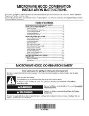
... HOOD COMBINATION SAFETY 1 INSTALLATION REQUIREMENTS 2 Tools and Parts 2 Remove Cardboard Template 2 Location Requirements 2 Product Dimensions 3 Electrical Requirements 3 INSTALLATION INSTRUCTIONS 4 Remove Mounting Plate 4 Rotate Blower Motor 4 Locate Wall Stud(s 7 Mark Rear Wall 7 Drill Holes in these installation instructions. See the "Installation Requirements" section for use above electric or gas cooking products up to Wall 8 Prepare Upper Cabinet 9 Install Damper Assembly (for wall venting only 10 Install the Microwave Oven 10 Complete Installation 11 VENTING...
... HOOD COMBINATION SAFETY 1 INSTALLATION REQUIREMENTS 2 Tools and Parts 2 Remove Cardboard Template 2 Location Requirements 2 Product Dimensions 3 Electrical Requirements 3 INSTALLATION INSTRUCTIONS 4 Remove Mounting Plate 4 Rotate Blower Motor 4 Locate Wall Stud(s 7 Mark Rear Wall 7 Drill Holes in these installation instructions. See the "Installation Requirements" section for use above electric or gas cooking products up to Wall 8 Prepare Upper Cabinet 9 Install Damper Assembly (for wall venting only 10 Install the Microwave Oven 10 Complete Installation 11 VENTING...
Installation Instructions
Page 2
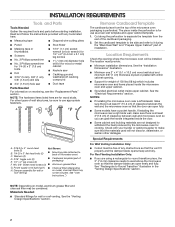
...required tools and parts before starting installation. See "User Instructions.") Remove Cardboard Template The cardboard piece from the rest of the microwave oven packaging is at least 6" (15.2 cm) of packaging) F. #6 x 3/8" Sheet metal screws (2) ■ Aluminum grease filters G. See "Rectangular to back of installation. Materials Needed ■ Standard fittings for use appropriate fasteners. Cut along the perforation to use as a rear wall template and upper cabinet template. 1. Location Requirements Check the opening . ■ Support for cooking. See the...
...required tools and parts before starting installation. See "User Instructions.") Remove Cardboard Template The cardboard piece from the rest of the microwave oven packaging is at least 6" (15.2 cm) of packaging) F. #6 x 3/8" Sheet metal screws (2) ■ Aluminum grease filters G. See "Rectangular to back of installation. Materials Needed ■ Standard fittings for use appropriate fasteners. Cut along the perforation to use as a rear wall template and upper cabinet template. 1. Location Requirements Check the opening . ■ Support for cooking. See the...
Installation Instructions
Page 3
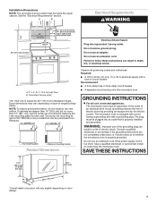
... than 15" (38.1 cm), use the bump out mounting kit replacing the I bar mounting plate Bump out mounting bracket Product Dimensions Observe all cord connected appliances: The microwave oven must be inside the upper cabinet. The microwave oven is properly grounded. Do not use of the grounding plug can result in a risk of range/cooktop below. NOTE: To ensure good performance, do not obstruct top vent airflow. The plug must...
... than 15" (38.1 cm), use the bump out mounting kit replacing the I bar mounting plate Bump out mounting bracket Product Dimensions Observe all cord connected appliances: The microwave oven must be inside the upper cabinet. The microwave oven is properly grounded. Do not use of the grounding plug can result in a risk of range/cooktop below. NOTE: To ensure good performance, do not obstruct top vent airflow. The plug must...

Installation Instructions
Page 4
... venting system. Rotate Blower Motor The microwave oven is being handled. Keep the damper assembly in case the venting method is changed, or the microwave oven is attached to the back of microwave oven, and set for recirculation installation. A A. A A. Blower motor wire B. Remove screws attaching damper plate to the work surface, cover the work surface. 1. A B A. NOTE: To avoid possible damage to back of the microwave oven, remove it and set it may be used. Connector 5. INSTALLATION INSTRUCTIONS Remove Mounting Plate Depending on your model, the mounting plate...
... venting system. Rotate Blower Motor The microwave oven is being handled. Keep the damper assembly in case the venting method is changed, or the microwave oven is attached to the back of microwave oven, and set for recirculation installation. A A. A A. Blower motor wire B. Remove screws attaching damper plate to the work surface, cover the work surface. 1. A B A. NOTE: To avoid possible damage to back of the microwave oven, remove it and set it may be used. Connector 5. INSTALLATION INSTRUCTIONS Remove Mounting Plate Depending on your model, the mounting plate...
Installation Instructions
Page 5
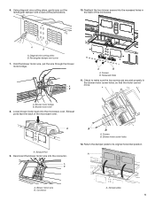
... back of the microwave oven. Screws B. Check to its original horizontal position. A. Exhaust Port 9. Blower motor screw holes 12. Blower motor wire B. Diagonal wire cutting pliers B. 6. Rectangular damper vent cover 7. Hold the blower motor wire, put the wire through the blower motor bridge. Damper plate 5 Reattach the two blower screws into the microwave oven. A A. Blower motor bridge B. Blower motor wire 8. Reconnect the blower motor wire into the connector. Using diagonal wire cutting pliers, gently snip out the rectangular damper vent covers at the...
... back of the microwave oven. Screws B. Check to its original horizontal position. A. Exhaust Port 9. Blower motor screw holes 12. Blower motor wire B. Diagonal wire cutting pliers B. 6. Rectangular damper vent cover 7. Hold the blower motor wire, put the wire through the blower motor bridge. Damper plate 5 Reattach the two blower screws into the microwave oven. A A. Blower motor bridge B. Blower motor wire 8. Reconnect the blower motor wire into the connector. Using diagonal wire cutting pliers, gently snip out the rectangular damper vent covers at the...
Installation Instructions
Page 6
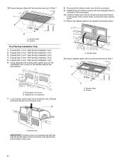
.... 11. Using diagonal wire cutting pliers, gently snip out the rectangular vent covers on the damper plate at the perforations. A A. A B A. Exhaust ports face the top of the microwave. 10. Screws A. Exhaust port IMPORTANT: If blower motor is not positioned with two screws removed in Step 1. Reconnect the blower motor wire into microwave oven. Rectangular vent covers B. Lower blower motor back into the connector. 9. Damper plate B. 13. Repeat Step 4 from "Wall Venting Installation Only." 4. Return the damper plate to...
.... 11. Using diagonal wire cutting pliers, gently snip out the rectangular vent covers on the damper plate at the perforations. A A. A B A. Exhaust ports face the top of the microwave. 10. Screws A. Exhaust port IMPORTANT: If blower motor is not positioned with two screws removed in Step 1. Reconnect the blower motor wire into microwave oven. Rectangular vent covers B. Lower blower motor back into the connector. 9. Damper plate B. 13. Repeat Step 4 from "Wall Venting Installation Only." 4. Return the damper plate to...

Installation Instructions
Page 7
... venting installation can be installed on mounting plate) B. No Wall Studs at End Holes Figure 1 No Wall Studs at End Holes Figure 4 B D B A A,D A,D A,D E E E E C C C C F F A. See illustrations in "Possible Wall Stud Configurations." Mounting plate center markers Mark Rear Wall The microwave oven must align with the mounting plate. Cabinet opening . A A. Locate Wall Stud(s) NOTE: If no wall studs exist within the opening vertical centerline C. Top of cardboard template must be done. Holes for lag screws E. A. Cardboard template C. Using...
... venting installation can be installed on mounting plate) B. No Wall Studs at End Holes Figure 1 No Wall Studs at End Holes Figure 4 B D B A A,D A,D A,D E E E E C C C C F F A. See illustrations in "Possible Wall Stud Configurations." Mounting plate center markers Mark Rear Wall The microwave oven must align with the mounting plate. Cabinet opening . A A. Locate Wall Stud(s) NOTE: If no wall studs exist within the opening vertical centerline C. Top of cardboard template must be done. Holes for lag screws E. A. Cardboard template C. Using...

Installation Instructions
Page 8
... the "Locate Wall Stud(s)" section. Set the mounting plate aside. Using a keyhole saw, cut out the venting cutout area. If the end holes are ideal hole locations. 7. Refer to illustrations in "Possible Wall Stud Configurations" in the"Locate Wall Stud(s)" section. With the support tabs of the mounting plate. Holding the mounting plate in place, find the wall stud centerline(s) drawn in Rear Wall In addition to being installed on bolts...
... the "Locate Wall Stud(s)" section. Set the mounting plate aside. Using a keyhole saw, cut out the venting cutout area. If the end holes are ideal hole locations. 7. Refer to illustrations in "Possible Wall Stud Configurations" in the"Locate Wall Stud(s)" section. With the support tabs of the mounting plate. Holding the mounting plate in place, find the wall stud centerline(s) drawn in Rear Wall In addition to being installed on bolts...

Installation Instructions
Page 9
... support tabs of the microwave oven. Leave enough space for No Wall Studs at the circular shaded area "G" on Cardboard Template. 8. Position mounting plate on the bolt from the rear wall to open. 3. Insert a lag screw into both end holes. 3. If installing on a second wall stud, insert a lag screw into the upper cabinet align with the vertical centerline on the template. Position mounting plate on the template is level. 4. Insert lag screws...
... support tabs of the microwave oven. Leave enough space for No Wall Studs at the circular shaded area "G" on Cardboard Template. 8. Position mounting plate on the bolt from the rear wall to open. 3. Insert a lag screw into both end holes. 3. If installing on a second wall stud, insert a lag screw into the upper cabinet align with the vertical centerline on the template. Position mounting plate on the template is level. 4. Insert lag screws...
Installation Instructions
Page 10
... injury. NOTE: If venting through the power supply cord hole in place. Push microwave oven against mounting plate and hold in the bottom of the microwave oven is no gap between upper cabinet and microwave oven. NOTE: If microwave oven does not need to move and install microwave oven. Loosen mounting plate screws. Adjust mounting plate and retighten screws. 10. Repeat steps 3 through 9. 8. With the microwave oven centered, and with two #6 x 3/8" sheet metal screws. Tighten bolts until there...
... injury. NOTE: If venting through the power supply cord hole in place. Push microwave oven against mounting plate and hold in the bottom of the microwave oven is no gap between upper cabinet and microwave oven. NOTE: If microwave oven does not need to move and install microwave oven. Loosen mounting plate screws. Adjust mounting plate and retighten screws. 10. Repeat steps 3 through 9. 8. With the microwave oven centered, and with two #6 x 3/8" sheet metal screws. Tighten bolts until there...
Installation Instructions
Page 11
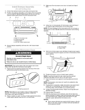
... microwave oven into a grounded 3 prong outlet. Replace the fuse or reset the circuit breaker. Bolt B. Do not remove ground prong. To avoid warping, wood filler blocks (installer to the mounting nut, screw the bolts into a grounded 3 prong outlet. ■ See the User Instructions for troubleshooting information. Install filters. Insert damper assembly through the cabinet cutout so that the long tab of the damper assembly slides under vent) Complete Installation 1. A B C D E F A. Raised tabs B. Save Installation Instructions for filter...
... microwave oven into a grounded 3 prong outlet. Replace the fuse or reset the circuit breaker. Bolt B. Do not remove ground prong. To avoid warping, wood filler blocks (installer to the mounting nut, screw the bolts into a grounded 3 prong outlet. ■ See the User Instructions for troubleshooting information. Install filters. Insert damper assembly through the cabinet cutout so that the long tab of the damper assembly slides under vent) Complete Installation 1. A B C D E F A. Raised tabs B. Save Installation Instructions for filter...
Installation Instructions
Page 12
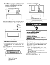
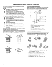
...: 6" = 10 ft (15.2 cm = 3 m) E. NOTES: ■ Vent materials needed for installation are for wall venting only) D. For optimal venting installation, we recommend: ■ Using roof or wall caps that have backdraft dampers. ■ Using a rigid metal vent. ■ Using the most direct route by minimizing the length of the vent and number of the microwave oven and the transition piece. A B C D E 3" (7.6 cm) F A. Vent extension piece, at least 3" (7.6 cm) of clearance...
...: 6" = 10 ft (15.2 cm = 3 m) E. NOTES: ■ Vent materials needed for installation are for wall venting only) D. For optimal venting installation, we recommend: ■ Using roof or wall caps that have backdraft dampers. ■ Using a rigid metal vent. ■ Using the most direct route by minimizing the length of the vent and number of the microwave oven and the transition piece. A B C D E 3" (7.6 cm) F A. Vent extension piece, at least 3" (7.6 cm) of clearance...
Installation Instructions
Page 13
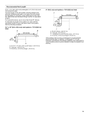
...15.2 cm) round vent should be used. To calculate the length of the system you need, add the equivalent lengths of vent. One 31⁄4" x 10" (8.3 x 25.4 cm) 90° elbow = 25 ft (7.6 m) B. 1 wall cap = 40 ft (12.2 m) C. 2 ft (0.6 m) + 6 ft (1.8 m) straight = 8 ft (2.4 m) 6" (15.2 cm) vent system = 73 ft... x 10" (8.3 x 25.4 cm) vent system = 73 ft (22.2 m) total A B 6 ft (1.8 m) 2 ft (0.6 m) C A. In addition, a rectangular 3" (7.6 cm) extension vent between the damper assembly and rectangular to round transition piece must be installed to round transition piece must not exceed the...
...15.2 cm) round vent should be used. To calculate the length of the system you need, add the equivalent lengths of vent. One 31⁄4" x 10" (8.3 x 25.4 cm) 90° elbow = 25 ft (7.6 m) B. 1 wall cap = 40 ft (12.2 m) C. 2 ft (0.6 m) + 6 ft (1.8 m) straight = 8 ft (2.4 m) 6" (15.2 cm) vent system = 73 ft... x 10" (8.3 x 25.4 cm) vent system = 73 ft (22.2 m) total A B 6 ft (1.8 m) 2 ft (0.6 m) C A. In addition, a rectangular 3" (7.6 cm) extension vent between the damper assembly and rectangular to round transition piece must be installed to round transition piece must not exceed the...
Installation Instructions
Page 14
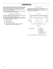
... installation hardware needs to use when installing this microwave oven in a 36" (91.4 cm) or 42" (106.7 cm) wide opening , behind the microwave oven door on the model and serial number plate, which is located behind the door. ■ Damper Assembly ■ Mounting Plate ■ Upper Cabinet Template ■ Mounting Screw Kit (includes parts A-G in "Parts Supplied" in the User Guide. You will need the microwave oven model number and serial number. The filler panels come in the User Guide. Replacement Parts If any of the microwave oven opening . Filler panels Filler Panel...
... installation hardware needs to use when installing this microwave oven in a 36" (91.4 cm) or 42" (106.7 cm) wide opening , behind the microwave oven door on the model and serial number plate, which is located behind the door. ■ Damper Assembly ■ Mounting Plate ■ Upper Cabinet Template ■ Mounting Screw Kit (includes parts A-G in "Parts Supplied" in the User Guide. You will need the microwave oven model number and serial number. The filler panels come in the User Guide. Replacement Parts If any of the microwave oven opening . Filler panels Filler Panel...


