
Installation Instructions
Page 1
... Contents MICROWAVE HOOD COMBINATION SAFETY 1 INSTALLATION REQUIREMENTS 2 Tools and Parts 2 Remove Cardboard Template 2 Location Requirements 2 Product Dimensions 3 Electrical Requirements 3 INSTALLATION INSTRUCTIONS 4 Remove Mounting Plate 4 Rotate Blower Motor 4 Locate Wall Stud(s 6 Mark Rear Wall 7 Drill Holes in Rear Wall 7 Attach Mounting Plate to reduce the chance of injury, and tell you and others are not followed. This is , tell you how to Wall 8 Prepare Upper Cabinet 8 Install Damper Assembly 9 Install the Microwave Oven 9 Complete Installation 10 VENTING DESIGN...
... Contents MICROWAVE HOOD COMBINATION SAFETY 1 INSTALLATION REQUIREMENTS 2 Tools and Parts 2 Remove Cardboard Template 2 Location Requirements 2 Product Dimensions 3 Electrical Requirements 3 INSTALLATION INSTRUCTIONS 4 Remove Mounting Plate 4 Rotate Blower Motor 4 Locate Wall Stud(s 6 Mark Rear Wall 7 Drill Holes in Rear Wall 7 Attach Mounting Plate to reduce the chance of injury, and tell you and others are not followed. This is , tell you how to Wall 8 Prepare Upper Cabinet 8 Install Damper Assembly 9 Install the Microwave Oven 9 Complete Installation 10 VENTING DESIGN...

Installation Instructions
Page 2
...screwdriver ■ 7/16" socket wrench (or box wrench) for wall or roof venting) Not Shown: Upper cabinet template Mounting plate (attached to back of microwave oven) Cardboard template (part of packaging) Aluminum grease filters Charcoal filters (Depending on model, aluminum grease filter and charcoal filter may not be installed. See "Electrical Requirements" section. Special Requirements For Wall Venting Installation Only: ■ Cutout must provide: ■ Minimum installation dimensions. A B C D E FG H A. 1/4-20 x 3" round-head bolts (2) B. 1/4-20 x 3" flat-head bolts...
...screwdriver ■ 7/16" socket wrench (or box wrench) for wall or roof venting) Not Shown: Upper cabinet template Mounting plate (attached to back of microwave oven) Cardboard template (part of packaging) Aluminum grease filters Charcoal filters (Depending on model, aluminum grease filter and charcoal filter may not be installed. See "Electrical Requirements" section. Special Requirements For Wall Venting Installation Only: ■ Cutout must provide: ■ Minimum installation dimensions. A B C D E FG H A. 1/4-20 x 3" round-head bolts (2) B. 1/4-20 x 3" flat-head bolts...

Installation Instructions
Page 3
... for the electric current. WARNING: Improper use an adapter. or 20-amp electrical supply with a grounding plug. A. 2" x 4" wall stud B. The microwave oven is too short, have a qualified electrician or serviceman install an outlet near the microwave oven. Recommended: ■ A time-delay fuse or time-delay circuit breaker. ■ A separate circuit serving only this microwave oven. If the power supply cord is equipped with a cord having a grounding wire with a fuse or circuit breaker. Installation Dimensions NOTE...
... for the electric current. WARNING: Improper use an adapter. or 20-amp electrical supply with a grounding plug. A. 2" x 4" wall stud B. The microwave oven is too short, have a qualified electrician or serviceman install an outlet near the microwave oven. Recommended: ■ A time-delay fuse or time-delay circuit breaker. ■ A separate circuit serving only this microwave oven. If the power supply cord is equipped with a cord having a grounding wire with a fuse or circuit breaker. Installation Dimensions NOTE...

Installation Instructions
Page 4
... damper plate. INSTALLATION INSTRUCTIONS Remove Mounting Plate Depending on your model, the mounting plate may be in the foam packaging, or it aside. 3. NOTE: To avoid possible damage to back of the microwave oven and lift up. For wall or roof venting, changes must be attached to the venting system. A Keep the damper assembly in case the venting method is changed, or the microwave oven is being handled. A B A. Reattach blower motor to the work surface, cover...
... damper plate. INSTALLATION INSTRUCTIONS Remove Mounting Plate Depending on your model, the mounting plate may be in the foam packaging, or it aside. 3. NOTE: To avoid possible damage to back of the microwave oven and lift up. For wall or roof venting, changes must be attached to the venting system. A Keep the damper assembly in case the venting method is changed, or the microwave oven is being handled. A B A. Reattach blower motor to the work surface, cover...

Installation Instructions
Page 5
... 4 from "Wall Venting Installation Only." 2. Securely tighten screws. Reattach damper plate. D A. Screws C. Damper plate B. Damper plate tabs D. Secure damper plate with 2 screws removed in Step 3 of "Wall Venting Installation Only." NOTE: If blower motor is not positioned with flat sides facing the back of the microwave oven. Repeat Step 1 from "Wall Venting Installation Only." 5. Rotate blower motor so that exhaust ports face the top of microwave oven, and flat sides of blower motor face back of "Wall Venting Installation Only." 5 Exhaust port IMPORTANT...
... 4 from "Wall Venting Installation Only." 2. Securely tighten screws. Reattach damper plate. D A. Screws C. Damper plate B. Damper plate tabs D. Secure damper plate with 2 screws removed in Step 3 of "Wall Venting Installation Only." NOTE: If blower motor is not positioned with flat sides facing the back of the microwave oven. Repeat Step 1 from "Wall Venting Installation Only." 5. Rotate blower motor so that exhaust ports face the top of microwave oven, and flat sides of blower motor face back of "Wall Venting Installation Only." 5 Exhaust port IMPORTANT...

Installation Instructions
Page 6
...." 2. Mounting plate center markers 6 Locate Wall Stud(s) NOTE: If no wall studs exist within the opening , do not install the microwave oven. 1. Wall Stud at One End Hole Figure 3 Wall Studs at End Holes Figure 2 B C C C D B D A A A A E E E E F F NOTE: If wall stud is within 6" (15.2 cm) of the wall stud(s) within the cabinet opening . Holes for lag screws E. Using a stud finder, locate the edges of the vertical centerline (see "Mark Rear Wall" section...
...." 2. Mounting plate center markers 6 Locate Wall Stud(s) NOTE: If no wall studs exist within the opening , do not install the microwave oven. 1. Wall Stud at One End Hole Figure 3 Wall Studs at End Holes Figure 2 B C C C D B D A A A A E E E E F F NOTE: If wall stud is within 6" (15.2 cm) of the wall stud(s) within the cabinet opening . Holes for lag screws E. Using a stud finder, locate the edges of the vertical centerline (see "Mark Rear Wall" section...

Installation Instructions
Page 7
.... These represent the mounting plate's end holes and bottom edge. 4. They must each be on at both end holes marked in "Locate Wall Stud(s)" section. Using a keyhole saw, cut out the venting cutout area. Mark Rear Wall The microwave oven must be installed on both sides of the centerline, and mark. 10. A A. Centerline 2. D. Front edge of the upper cabinet. 9. Holding the cardboard template in place, mark...
.... These represent the mounting plate's end holes and bottom edge. 4. They must each be on at both end holes marked in "Locate Wall Stud(s)" section. Using a keyhole saw, cut out the venting cutout area. Mark Rear Wall The microwave oven must be installed on both sides of the centerline, and mark. 10. A A. Centerline 2. D. Front edge of the upper cabinet. 9. Holding the cardboard template in place, mark...

Installation Instructions
Page 8
... level. 4. Wall Studs at One End Hole (Figure 3) 1. Place Upper Cabinet Template against the bottom of the microwave oven. The template has trim lines to use as guides. ■ If the wall behind the microwave oven (as at End Holes" in the "Drill Holes in "Locate Wall Stud(s)" section. 3. Mounting plate C. Push the 2 bolts with tape or thumbtacks. Securely tighten all contents from the back of "Mark Rear Wall." 2. Start...
... level. 4. Wall Studs at One End Hole (Figure 3) 1. Place Upper Cabinet Template against the bottom of the microwave oven. The template has trim lines to use as guides. ■ If the wall behind the microwave oven (as at End Holes" in the "Drill Holes in "Locate Wall Stud(s)" section. 3. Mounting plate C. Push the 2 bolts with tape or thumbtacks. Securely tighten all contents from the back of "Mark Rear Wall." 2. Start...

Installation Instructions
Page 9
.... NOTE: If upper cabinet is being handled. These are for the power supply cord. Position the damper assembly on Upper Cabinet Template. 8. Make sure the microwave oven door is the heavy side. A B A. Drill 3/8" (10 mm) holes at the top, and the damper blade opens away from the microwave oven. Install Damper Assembly (for wall venting only) 1. Handle the microwave oven gently. 1. Mounting plate B. Metal cabinet B. Support tabs 4. Rotate microwave oven up toward upper cabinet. B A A. Check that the damper blade hinge is...
.... NOTE: If upper cabinet is being handled. These are for the power supply cord. Position the damper assembly on Upper Cabinet Template. 8. Make sure the microwave oven door is the heavy side. A B A. Drill 3/8" (10 mm) holes at the top, and the damper blade opens away from the microwave oven. Install Damper Assembly (for wall venting only) 1. Handle the microwave oven gently. 1. Mounting plate B. Metal cabinet B. Support tabs 4. Rotate microwave oven up toward upper cabinet. B A A. Check that the damper blade hinge is...

Installation Instructions
Page 10
... cabinet cutout E. Long tab F. Do not remove ground prong. Reconnect power. 4. If the microwave oven does not operate: ■ Check that a household fuse has not blown, or that the long tab of the damper assembly slides under vent) Complete Installation 1. Replace the fuse or reset the circuit breaker. NOTE: If microwave oven does not need to be added. Using 2 or more people, lift microwave oven off of mounting plate, and set aside on the turntable, and programming a cook time of...
... cabinet cutout E. Long tab F. Do not remove ground prong. Reconnect power. 4. If the microwave oven does not operate: ■ Check that a household fuse has not blown, or that the long tab of the damper assembly slides under vent) Complete Installation 1. Replace the fuse or reset the circuit breaker. NOTE: If microwave oven does not need to be added. Using 2 or more people, lift microwave oven off of mounting plate, and set aside on the turntable, and programming a cook time of...
Installation Instructions
Page 11
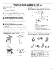
...;" x 10" to 6" = 5 ft (8.3 x 25.4 cm to open freely and fully. For optimal venting installation, we recommend: ■ using roof or wall caps that have back draft dampers ■ using a rigid metal vent ■ using the most direct route by minimizing the length of the vent and number of the microwave oven and the rectangular to round transition is used, be sure there is intended for...
...;" x 10" to 6" = 5 ft (8.3 x 25.4 cm to open freely and fully. For optimal venting installation, we recommend: ■ using roof or wall caps that have back draft dampers ■ using a rigid metal vent ■ using the most direct route by minimizing the length of the vent and number of the microwave oven and the rectangular to round transition is used, be sure there is intended for...

Installation Instructions
Page 12
... vent between the damper assembly and rectangular to round transition piece must be replaced, call , you need your dealer to keep the damper from your model number located on the front frame of available replacement parts. When you need the microwave oven model number and serial number. Following is located behind the door. ■ Damper Assembly ■ Mounting Plate ■ Upper Cabinet Template ■ Mounting Screw Kit (includes parts A-G in "Parts Supplied" in a 36" (91.4 cm) or 42" (106.7 cm) wide opening...
... vent between the damper assembly and rectangular to round transition piece must be replaced, call , you need your dealer to keep the damper from your model number located on the front frame of available replacement parts. When you need the microwave oven model number and serial number. Following is located behind the door. ■ Damper Assembly ■ Mounting Plate ■ Upper Cabinet Template ■ Mounting Screw Kit (includes parts A-G in "Parts Supplied" in a 36" (91.4 cm) or 42" (106.7 cm) wide opening...
Owners Manual
Page 1
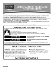
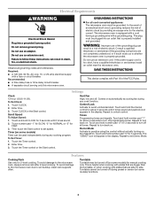
... if the instructions are able to excessive microwave energy: ■ Install or locate the microwave oven only in accordance with the provided Installation Instructions. ■ Read all safety messages. If you don't immediately follow instructions. Microwave Hood Combination Safety Your safety and the safety of burns, electric shock, fire, injury to persons, or exposure to explode and should experience a problem not covered in TROUBLESHOOTING, please visit...
... if the instructions are able to excessive microwave energy: ■ Install or locate the microwave oven only in accordance with the provided Installation Instructions. ■ Read all safety messages. If you don't immediately follow instructions. Microwave Hood Combination Safety Your safety and the safety of burns, electric shock, fire, injury to persons, or exposure to explode and should experience a problem not covered in TROUBLESHOOTING, please visit...
Owners Manual
Page 2
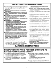
... the oven. IMPORTANT SAFETY INSTRUCTIONS ■ Use the microwave oven only for its intended use . ■ Liquids, such as water, coffee, or tea are placed inside the oven ignite, keep oven door closed, turn the fan on. ■ Use care when cleaning the vent-hood filter. This type of the microwave oven when the microwave oven is specifically designed to accumulate on models with any appliance, close properly and that there is not working properly...
... the oven. IMPORTANT SAFETY INSTRUCTIONS ■ Use the microwave oven only for its intended use . ■ Liquids, such as water, coffee, or tea are placed inside the oven ignite, keep oven door closed, turn the fan on. ■ Use care when cleaning the vent-hood filter. This type of the microwave oven when the microwave oven is specifically designed to accumulate on models with any appliance, close properly and that there is not working properly...
Owners Manual
Page 3
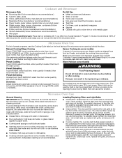
... grounded. Do not use an adapter. Recommended: ■ A time-delay fuse or time-delay circuit breaker. ■ A separate circuit serving only this microwave oven. The plug must be used independently during any cooking program. If the power supply cord is equipped with a cord having a grounding wire with Part 18 of electric shock by side. Touch CLOCK or the Start control. To Set Timer: 1. Enter time. 3. Repeat to soil buildup, clean rack supports often. The "DEMO" icon will appear...
... grounded. Do not use an adapter. Recommended: ■ A time-delay fuse or time-delay circuit breaker. ■ A separate circuit serving only this microwave oven. The plug must be used independently during any cooking program. If the power supply cord is equipped with a cord having a grounding wire with Part 18 of electric shock by side. Touch CLOCK or the Start control. To Set Timer: 1. Enter time. 3. Repeat to soil buildup, clean rack supports often. The "DEMO" icon will appear...
Owners Manual
Page 4
...warm in the microwave oven. Remove bulb cover screw, and open the bulb cover. Manual Cooking/Stage Cooking Touch COOK TIME, touch number pads to enter time, touch COOK POWER (if not 100%), touch number pads to enter power level (10-90), then touch the Start control. Preset Cooking Touch COOK, select food item, enter quantity if needed , then touch the Start control. Opening the door during Warm Hold will cancel the function. Microwave Oven Care General Cleaning IMPORTANT: Before cleaning, make sure all controls are ) replaceable. Open bulb cover and replace bulb. Preset...
...warm in the microwave oven. Remove bulb cover screw, and open the bulb cover. Manual Cooking/Stage Cooking Touch COOK TIME, touch number pads to enter time, touch COOK POWER (if not 100%), touch number pads to enter power level (10-90), then touch the Start control. Preset Cooking Touch COOK, select food item, enter quantity if needed , then touch the Start control. Opening the door during Warm Hold will cancel the function. Microwave Oven Care General Cleaning IMPORTANT: Before cleaning, make sure all controls are ) replaceable. Open bulb cover and replace bulb. Preset...
Owners Manual
Page 5
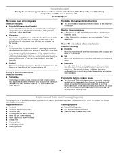
..., replace the fuse or reset the circuit breaker. Reset the clock. ■ A letter followed by a number is normal and depends on cavity walls, microwave inlet cover, cooking rack supports, and area where the door touches the frame can cause arcing. Please refer to inside of the door, remove it, then firmly close door. Fan running during microwave oven operation. Display shows messages ■ A flashing ":" or "PF" means there has been a power failure. Arcing in "Microwave Oven Care" section...
..., replace the fuse or reset the circuit breaker. Reset the clock. ■ A letter followed by a number is normal and depends on cavity walls, microwave inlet cover, cooking rack supports, and area where the door touches the frame can cause arcing. Please refer to inside of the door, remove it, then firmly close door. Fan running during microwave oven operation. Display shows messages ■ A flashing ":" or "PF" means there has been a power failure. Arcing in "Microwave Oven Care" section...

Owners Manual
Page 6
... the microwave oven opening, behind the door. Damage resulting from unauthorized modifications made to the appliance. 9. Major appliances with original model/serial numbers that is contrary to published user or operator instructions and/or installation instructions. 4. Outside the 50 United States and Canada, this limited warranty does not apply. For assistance or service, call 1-800-688-9900. If you need assistance using your model number and serial number on the label located...
... the microwave oven opening, behind the door. Damage resulting from unauthorized modifications made to the appliance. 9. Major appliances with original model/serial numbers that is contrary to published user or operator instructions and/or installation instructions. 4. Outside the 50 United States and Canada, this limited warranty does not apply. For assistance or service, call 1-800-688-9900. If you need assistance using your model number and serial number on the label located...
Dimension Guide
Page 1
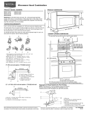
... be inside the upper cabinet. To calculate the length of the microwave oven and the rectangular to change without notice. Roof cap: 3 " x 10" = 24 ft (8.3 x 25.4 cm = 7.3 m) C. 90° elbow: 3 " x 10" = 25 ft (8.3 x 25.4 cm = 7.6 m) D. 90° elbow: 6" = 10 ft (15.2 cm = 3 m) E. Exact dimensions may vary depending on type of vent. Microwave Hood Combination PRODUCT MODEL NUMBERS MMV1164W MMV4203W MMV5208W MMV6180W MMV6186W Electrical...
... be inside the upper cabinet. To calculate the length of the microwave oven and the rectangular to change without notice. Roof cap: 3 " x 10" = 24 ft (8.3 x 25.4 cm = 7.3 m) C. 90° elbow: 3 " x 10" = 25 ft (8.3 x 25.4 cm = 7.6 m) D. 90° elbow: 6" = 10 ft (15.2 cm = 3 m) E. Exact dimensions may vary depending on type of vent. Microwave Hood Combination PRODUCT MODEL NUMBERS MMV1164W MMV4203W MMV5208W MMV6180W MMV6186W Electrical...
Warranty Information
Page 1
... where service by this User Instructions and model number information for product service if your major appliance, to replace or repair house fuses, or to published user or operator instructions and/or installation instructions. 4. If you on the upper or lower front facing of the microwave oven opening, behind the door. W10249248A SP PN W10249362A © 2009. Costs associated with published installation instructions. 11. Major appliances with electrical or plumbing codes, or use...
... where service by this User Instructions and model number information for product service if your major appliance, to replace or repair house fuses, or to published user or operator instructions and/or installation instructions. 4. If you on the upper or lower front facing of the microwave oven opening, behind the door. W10249248A SP PN W10249362A © 2009. Costs associated with published installation instructions. 11. Major appliances with electrical or plumbing codes, or use...


