Owners Manual
Page 5
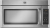
...Frequency Some 2.4 GHz-based cordless phones and home wireless networks may experience static or noise while microwave oven is normal and depends on cavity walls, microwave inlet cover, cooking rack supports, and area where the door touches the frame can cause arcing. Please refer to inside of ..., then start the cycle. ■ Control Make sure control is being started. www.maytag.com Microwave oven will not operate Check the following : ■ Proximity Move the receiver away from the vent fan, automatically comes on some models), which may also automatically come on and cycle on...
...Frequency Some 2.4 GHz-based cordless phones and home wireless networks may experience static or noise while microwave oven is normal and depends on cavity walls, microwave inlet cover, cooking rack supports, and area where the door touches the frame can cause arcing. Please refer to inside of ..., then start the cycle. ■ Control Make sure control is being started. www.maytag.com Microwave oven will not operate Check the following : ■ Proximity Move the receiver away from the vent fan, automatically comes on some models), which may also automatically come on and cycle on...
Installation Instructions
Page 1
... Requirements 2 Product Dimensions 3 Electrical Requirements 3 INSTALLATION INSTRUCTIONS 4 Remove Mounting Plate 4 Rotate Blower Motor 4 Locate Wall Stud(s 6 Mark Rear Wall 7 Drill Holes in this manual and on your particular model may differ slightly from the illustration in these installation ... have provided many important safety messages in Rear Wall 7 Attach Mounting Plate to Wall 8 Prepare Upper Cabinet 8 Install Damper Assembly 9 Install the Microwave Oven 9 Complete Installation 10 VENTING DESIGN SPECIFICATIONS 11 ASSISTANCE 12 Replacement Parts 12 Accessories...
... Requirements 2 Product Dimensions 3 Electrical Requirements 3 INSTALLATION INSTRUCTIONS 4 Remove Mounting Plate 4 Rotate Blower Motor 4 Locate Wall Stud(s 6 Mark Rear Wall 7 Drill Holes in this manual and on your particular model may differ slightly from the illustration in these installation ... have provided many important safety messages in Rear Wall 7 Attach Mounting Plate to Wall 8 Prepare Upper Cabinet 8 Install Damper Assembly 9 Install the Microwave Oven 9 Complete Installation 10 VENTING DESIGN SPECIFICATIONS 11 ASSISTANCE 12 Replacement Parts 12 Accessories...
Installation Instructions
Page 2
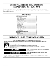
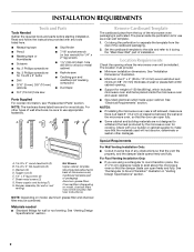
...Scissors ■ No. 2 Phillips screwdriver ■ 7/16" socket wrench (or box wrench) for use appropriate fasteners. Special Requirements For Wall Venting Installation Only: ■ Cutout must provide: ■ Minimum installation dimensions. NOTE: The hardware items listed here are not designed to ... sure there is perforated. The location must be installed. hole drill bit for wood or metal cabinet ■ No. 3 Phillips screwdriver for wall or roof venting. Materials needed ■ Standard fittings for 1/4-20 x 3" bolts ■ Drill ■ 3/16" (5 mm), 3/8" (10 mm)...
...Scissors ■ No. 2 Phillips screwdriver ■ 7/16" socket wrench (or box wrench) for use appropriate fasteners. Special Requirements For Wall Venting Installation Only: ■ Cutout must provide: ■ Minimum installation dimensions. NOTE: The hardware items listed here are not designed to ... sure there is perforated. The location must be installed. hole drill bit for wood or metal cabinet ■ No. 3 Phillips screwdriver for wall or roof venting. Materials needed ■ Standard fittings for 1/4-20 x 3" bolts ■ Drill ■ 3/16" (5 mm), 3/8" (10 mm)...
Installation Instructions
Page 4
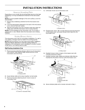
...Lift blower motor out of the microwave oven and lift up. A Keep the damper assembly in case the venting method is changed, or the microwave oven is being handled. Wall Venting Installation Only 1. A B A. Damper plate B. NOTE: To avoid possible damage to top of the microwave...7. Slide damper plate toward the front of microwave oven. Slots 8. Make sure damper plate tabs are using recirculation installation. For wall or roof venting, changes must be used. Reattach blower motor to back of microwave oven with 2 screws removed in recessed holes) D A. Remove...
...Lift blower motor out of the microwave oven and lift up. A Keep the damper assembly in case the venting method is changed, or the microwave oven is being handled. Wall Venting Installation Only 1. A B A. Damper plate B. NOTE: To avoid possible damage to top of the microwave...7. Slide damper plate toward the front of microwave oven. Slots 8. Make sure damper plate tabs are using recirculation installation. For wall or roof venting, changes must be used. Reattach blower motor to back of microwave oven with 2 screws removed in recessed holes) D A. Remove...
Installation Instructions
Page 5
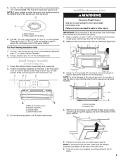
...blower motor so that exhaust ports face the top of microwave oven, and flat sides of blower motor face back of "Wall Venting Installation Only." 5 Lower blower motor back into the slots in Step 3 cannot be poor. NOTE: If blower motor...are inserted into microwave oven. Repeat Step 4 from "Wall Venting Installation Only." 2. A B C A. Repeat Step 1 from "Wall Venting Installation Only." 5. A 6. Exhaust port IMPORTANT: If blower motor is not correctly oriented, the 2 screws removed in the top of "Wall Venting Installation Only." Slots 8. Reattach blower motor to the ...
...blower motor so that exhaust ports face the top of microwave oven, and flat sides of blower motor face back of "Wall Venting Installation Only." 5 Lower blower motor back into the slots in Step 3 cannot be poor. NOTE: If blower motor...are inserted into microwave oven. Repeat Step 4 from "Wall Venting Installation Only." 2. A B C A. Repeat Step 1 from "Wall Venting Installation Only." 5. A 6. Exhaust port IMPORTANT: If blower motor is not correctly oriented, the 2 screws removed in the top of "Wall Venting Installation Only." Slots 8. Reattach blower motor to the ...
Installation Instructions
Page 6
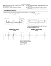
... screws E. Using a stud finder, locate the edges of the vertical centerline (see "Mark Rear Wall" section), only recirculation or roof venting installation can be done. Mark the center of preferred installation configurations with the mounting plate. Support tabs F. Wall stud centerlines D. Cabinet opening . Mounting plate center markers 6 End holes (on mounting plate) B. Locate...
... screws E. Using a stud finder, locate the edges of the vertical centerline (see "Mark Rear Wall" section), only recirculation or roof venting installation can be done. Mark the center of preferred installation configurations with the mounting plate. Support tabs F. Wall stud centerlines D. Cabinet opening . Mounting plate center markers 6 End holes (on mounting plate) B. Locate...
Installation Instructions
Page 7
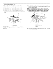
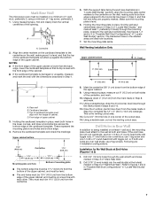
... in Step 4. See figures 1, 2 and/or 3 in "Possible Wall Stud Configurations" in Step 9 to being installed on the wall, making sure it is level, and that its bottom edge is the venting cutout area. 13. Drill Holes in Step 6 of the cutout area...(30.5 x 10.2 cm) rectangle. Drill 3/16" (5 mm) hole(s) into the wall stud(s) at End Holes (Figures 1 & 2) 1. Make sure the mounting plate is over a wall stud, use 1 lag screw and one corner of "Mark Rear Wall." Wall Venting Installation Only Upper cabinet bottom ³⁄₈" (1 cm) 4" (10.2 cm) Centerline...
... in Step 4. See figures 1, 2 and/or 3 in "Possible Wall Stud Configurations" in Step 9 to being installed on the wall, making sure it is level, and that its bottom edge is the venting cutout area. 13. Drill Holes in Step 6 of the cutout area...(30.5 x 10.2 cm) rectangle. Drill 3/16" (5 mm) hole(s) into the wall stud(s) at End Holes (Figures 1 & 2) 1. Make sure the mounting plate is over a wall stud, use 1 lag screw and one corner of "Mark Rear Wall." Wall Venting Installation Only Upper cabinet bottom ³⁄₈" (1 cm) 4" (10.2 cm) Centerline...
Installation Instructions
Page 9
... handled. Metal cabinet B. NOTE: To avoid damage to move and install microwave oven. A. Sheet metal screws 3. Mounting plate B. For Roof Venting Installation Only 7. Check that the damper blade hinge is closed and taped shut. 3. Damper assembly C. Failure to do not grip or use the...Template. 8. Make sure the microwave oven door is at the top, and the damper blade opens away from the microwave oven. These are for wall venting only) 1. Place a washer on the template. This hole is the heavy side. Install Damper Assembly (for two 1/4-20 x 3" bolts ...
... handled. Metal cabinet B. NOTE: To avoid damage to move and install microwave oven. A. Sheet metal screws 3. Mounting plate B. For Roof Venting Installation Only 7. Check that the damper blade hinge is closed and taped shut. 3. Damper assembly C. Failure to do not grip or use the...Template. 8. Make sure the microwave oven door is at the top, and the damper blade opens away from the microwave oven. These are for wall venting only) 1. Place a washer on the template. This hole is the heavy side. Install Damper Assembly (for two 1/4-20 x 3" bolts ...
Installation Instructions
Page 11
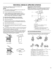
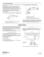
... designer and builder/contractor reference only. A B C Roof venting Roof cap Wall venting Wall cap D E F G A. A B C D E 3" (7.6 cm) F A. Wall cap E. 3¹⁄₄" x 10" to 6" (8.3 x 25.4 cm to 15.2 cm) rectangular to 15.2 cm = 1.5 m) B. See the examples in the vent system ■ using roof or wall caps that there is intended for wall venting only) D. VENTING DESIGN SPECIFICATIONS This section is proper clearance...
... designer and builder/contractor reference only. A B C Roof venting Roof cap Wall venting Wall cap D E F G A. A B C D E 3" (7.6 cm) F A. Wall cap E. 3¹⁄₄" x 10" to 6" (8.3 x 25.4 cm to 15.2 cm) rectangular to 15.2 cm = 1.5 m) B. See the examples in the vent system ■ using roof or wall caps that there is intended for wall venting only) D. VENTING DESIGN SPECIFICATIONS This section is proper clearance...
Installation Instructions
Page 12
... 3" (7.6 cm) wide. To calculate the length of the system you will need , add the equivalent lengths of each vent piece used . Two 90° elbows = 20 ft (6.1 m) B. 1 wall cap = 40 ft (12.2 m) C. 1 rectangular to round transition piece must not exceed the equivalent of available replacement ...9632; Mounting Screw Kit (includes parts A-G in "Parts Supplied" in the User Instructions. The total length of the vent system including straight vent, elbow(s), transitions and wall or roof caps must be installed to keep the damper from your authorized dealer or service center for either type of...
... 3" (7.6 cm) wide. To calculate the length of the system you will need , add the equivalent lengths of each vent piece used . Two 90° elbows = 20 ft (6.1 m) B. 1 wall cap = 40 ft (12.2 m) C. 1 rectangular to round transition piece must not exceed the equivalent of available replacement ...9632; Mounting Screw Kit (includes parts A-G in "Parts Supplied" in the User Instructions. The total length of the vent system including straight vent, elbow(s), transitions and wall or roof caps must be installed to keep the damper from your authorized dealer or service center for either type of...


