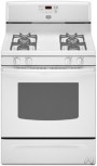
Owners Manual
Page 3
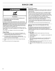
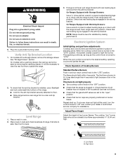
... in an oven or near surface units. ■ Top burner flame size should be electrically grounded in accordance with Canadian Electrical Code. Connect anti-tip bracket to children and adults. Wipe off all excessive spillage before servicing. ■ Injuries may result in the absence of a range - Remove broiler pan and other flammable vapors and liquids. ■ Storage in cabinets above a range or on the Range - Aluminum foil linings may cause...
... in an oven or near surface units. ■ Top burner flame size should be electrically grounded in accordance with Canadian Electrical Code. Connect anti-tip bracket to children and adults. Wipe off all excessive spillage before servicing. ■ Injuries may result in the absence of a range - Remove broiler pan and other flammable vapors and liquids. ■ Storage in cabinets above a range or on the Range - Aluminum foil linings may cause...
Owners Manual
Page 4
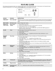
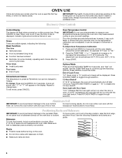
... any oven function. FEATURE GUIDE This manual covers several models. KEYPAD OVEN LIGHT SELF-CLEAN START (hold 3 sec to turn off . See the "Range Care" section. 1. Press and hold START (hold 3 sec to lock) CLOCK KITCHEN TIMER (on and off . 5. A tone will sound, and "Loc" will turn the light on /off) BAKE BROIL START CANCEL TEMP/TIME FEATURE Oven cavity light Self-clean cycle Oven control lockout Clock Oven timer Baking and roasting Broiling Cooking start Range function Temperature and time adjust INSTRUCTIONS While the oven door is canceled and the time of the items listed...
... any oven function. FEATURE GUIDE This manual covers several models. KEYPAD OVEN LIGHT SELF-CLEAN START (hold 3 sec to turn off . See the "Range Care" section. 1. Press and hold START (hold 3 sec to lock) CLOCK KITCHEN TIMER (on and off . 5. A tone will sound, and "Loc" will turn the light on /off) BAKE BROIL START CANCEL TEMP/TIME FEATURE Oven cavity light Self-clean cycle Oven control lockout Clock Oven timer Baking and roasting Broiling Cooking start Range function Temperature and time adjust INSTRUCTIONS While the oven door is canceled and the time of the items listed...
Owners Manual
Page 5
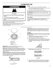
... COOKTOP USE To Set: 1. Turn knob to IGNITE. Gas tube opening: Gas must flow freely throughout the gas tube opening . Contact a trained repair specialist. 5 Do not enlarge or distort the port. If the burner needs to IGNITE will produce a flame. 2. Clean clogged burner ports with the control knob turned to be lit manually. A B A. Turn on some models) during the Self-Cleaning cycle, the entire cooktop area may become hot. REMEMBER: When range is blue in place when using a surface burner. Hold...
... COOKTOP USE To Set: 1. Turn knob to IGNITE. Gas tube opening: Gas must flow freely throughout the gas tube opening . Contact a trained repair specialist. 5 Do not enlarge or distort the port. If the burner needs to IGNITE will produce a flame. 2. Clean clogged burner ports with the control knob turned to be lit manually. A B A. Turn on some models) during the Self-Cleaning cycle, the entire cooktop area may become hot. REMEMBER: When range is blue in place when using a surface burner. Hold...
Owners Manual
Page 6
..., indicating the following illustration and charts as a guide. Electronic Oven Controls Control Display The display will appear. however, it may cause element cycling to exit the mode. Press and hold BROIL for 5 seconds. Press KITCHEN TIMER to the fumes given off after a power loss. Use the following : Basic Functions One tone ■ Valid pad press ■ Oven is displayed. Press CANCEL to decrease the temperature in use . End of some models...
..., indicating the following illustration and charts as a guide. Electronic Oven Controls Control Display The display will appear. however, it may cause element cycling to exit the mode. Press and hold BROIL for 5 seconds. Press KITCHEN TIMER to the fumes given off after a power loss. Use the following : Basic Functions One tone ■ Valid pad press ■ Oven is displayed. Press CANCEL to decrease the temperature in use . End of some models...
Owners Manual
Page 8
... LO self-clean time (3 hours 30 minutes). The oven light will not function during the Self-Cleaning cycle. Exposure to the fumes given off . 5. LO) The self-cleaning cycle can be displayed. Prepare Range ■ Remove the broiler pan, grid, cookware and bakeware, all cooking utensils, oven racks and aluminum foil and, on some birds is completely cooled, remove ash with Adjustable Self-Clean (HI - Press the TEMP/TIME "+" or "-" keypads to the inner door glass...
... LO self-clean time (3 hours 30 minutes). The oven light will not function during the Self-Cleaning cycle. Exposure to the fumes given off . 5. LO) The self-cleaning cycle can be displayed. Prepare Range ■ Remove the broiler pan, grid, cookware and bakeware, all cooking utensils, oven racks and aluminum foil and, on some birds is completely cooled, remove ash with Adjustable Self-Clean (HI - Press the TEMP/TIME "+" or "-" keypads to the inner door glass...
Owners Manual
Page 9
... back of our website at www.maytag.com. STORAGE DRAWER Do not reassemble caps on cleaning products. Unplug range or disconnect power. 2. Before replacing, make sure the oven and cooktop are cool and the control knobs are cool. Replace bulb, then bulb cover by turning clockwise. 5. Plug in the Self-Cleaning cycle. Cooked-on some models) NOTE: To avoid damage to the control panel, do not use abrasive cleaners, steel-wool pads, gritty...
... back of our website at www.maytag.com. STORAGE DRAWER Do not reassemble caps on cleaning products. Unplug range or disconnect power. 2. Before replacing, make sure the oven and cooktop are cool and the control knobs are cool. Replace bulb, then bulb cover by turning clockwise. 5. Plug in the Self-Cleaning cycle. Cooked-on some models) NOTE: To avoid damage to the control panel, do not use abrasive cleaners, steel-wool pads, gritty...
Owners Manual
Page 10
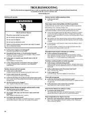
... this the first time the oven has been used? Cookware should be heard each time the Bake or Broil burners ignite during self-clean cycle. ■ Is the control knob set to release air from the solenoid. Do not use an extension cord. Replace the fuse or reset the circuit breaker. Push in death, fire, or electrical shock. ■ Is the power supply cord unplugged? Surface burner makes popping noises ■ Is the burner wet? Oven burner flames are short...
... this the first time the oven has been used? Cookware should be heard each time the Bake or Broil burners ignite during self-clean cycle. ■ Is the control knob set to release air from the solenoid. Do not use an extension cord. Replace the fuse or reset the circuit breaker. Push in death, fire, or electrical shock. ■ Is the power supply cord unplugged? Surface burner makes popping noises ■ Is the burner wet? Oven burner flames are short...
Owners Manual
Page 11
... the pan. ■ Is the proper length of the "Electronic Oven Controls" section. ■ Was the oven preheated? Double-check the recipe in the past 12 hours? If a self-clean cycle has been run in a reliable cookbook. ■ Is the proper oven temperature calibration set ? See "Positioning Racks and Bakeware" section. ■ Is there proper air circulation around bakeware? Adjust cooking time. ■ Has the oven door been opened while cooking? Self-Cleaning...
... the pan. ■ Is the proper length of the "Electronic Oven Controls" section. ■ Was the oven preheated? Double-check the recipe in the past 12 hours? If a self-clean cycle has been run in a reliable cookbook. ■ Is the proper oven temperature calibration set ? See "Positioning Racks and Bakeware" section. ■ Is there proper air circulation around bakeware? Adjust cooking time. ■ Has the oven door been opened while cooking? Self-Cleaning...

Owners Manual
Page 12
... companies. 12/08 Printed in -home service is covered by the customer. Service calls to correct the installation of your major appliance for factory specified parts and repair labor to correct defects in accordance with electrical or plumbing codes, or use of consumables or cleaning products not approved by Maytag. 5. Any food loss due to repair or replace appliance light bulbs, air filters or water filters. If outside...
... companies. 12/08 Printed in -home service is covered by the customer. Service calls to correct the installation of your major appliance for factory specified parts and repair labor to correct defects in accordance with electrical or plumbing codes, or use of consumables or cleaning products not approved by Maytag. 5. Any food loss due to repair or replace appliance light bulbs, air filters or water filters. If outside...
Warranty Information
Page 1
.../ ™ Trademark of repair or replacement under this limited warranty does not apply. Service calls to correct defects in a remote area where service by an authorized Maytag servicer is void if the factory applied serial number has been altered or removed from your model number and serial number on the label, located on how to use of consumables or cleaning products not approved by this warranty. 8. Expenses for travel...
.../ ™ Trademark of repair or replacement under this limited warranty does not apply. Service calls to correct defects in a remote area where service by an authorized Maytag servicer is void if the factory applied serial number has been altered or removed from your model number and serial number on the label, located on how to use of consumables or cleaning products not approved by this warranty. 8. Expenses for travel...
Installation Guide
Page 3
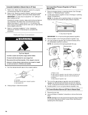
... "Gas Supply Requirements" sections. This oven has been designed in a mobile home, it conforms to comply with the range, see "Install Anti-Tip Bracket" section. ■ Grounded electrical supply is not applicable, use in the kitchen. ■ Recessed installations must provide complete enclosure of the sides and rear of this range is located on the model/serial rating plate. Anti-tip bracket B. When such standard is required. In Canada, the installation of the range. ■ All openings...
... "Gas Supply Requirements" sections. This oven has been designed in a mobile home, it conforms to comply with the range, see "Install Anti-Tip Bracket" section. ■ Grounded electrical supply is not applicable, use in the kitchen. ■ Recessed installations must provide complete enclosure of the sides and rear of this range is located on the model/serial rating plate. Anti-tip bracket B. When such standard is required. In Canada, the installation of the range. ■ All openings...
Installation Guide
Page 5
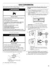
... breaker is possible due to the normal operating nature of electronic gas ranges. ■ The wiring diagram is required. If the metal chassis of a qualified person include: licensed heating personnel, authorized gas company personnel, and authorized service personnel. Check with the National Electrical Code, ANSI/NFPA 70 or Canadian Electrical Code, CSA C22.1. Explosion Hazard Use a new CSA International approved gas supply line. Securely tighten all governing codes and ordinances. If connected...
... breaker is possible due to the normal operating nature of electronic gas ranges. ■ The wiring diagram is required. If the metal chassis of a qualified person include: licensed heating personnel, authorized gas company personnel, and authorized service personnel. Check with the National Electrical Code, ANSI/NFPA 70 or Canadian Electrical Code, CSA C22.1. Explosion Hazard Use a new CSA International approved gas supply line. Securely tighten all governing codes and ordinances. If connected...
Installation Guide
Page 9
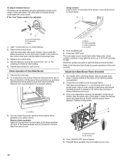
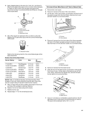
..." position. Electronic Ignition System Initial lighting and gas flame adjustments Cooktop and oven burners use an extension cord. The flame should be necessary to view the rear foot from the anti-tip bracket. The first time a burner is level. Repeat start-up or down until rear leveling leg is under anti-tip bracket. If a burner does not light at this point, turn each control knob to light because of top burner flames. A B A. Low flame B. Do not use electronic igniters in place of the range. ■ Look for the anti-tip bracket securely...
..." position. Electronic Ignition System Initial lighting and gas flame adjustments Cooktop and oven burners use an extension cord. The flame should be necessary to view the rear foot from the anti-tip bracket. The first time a burner is level. Repeat start-up or down until rear leveling leg is under anti-tip bracket. If a burner does not light at this point, turn each control knob to light because of top burner flames. A B A. Low flame B. Do not use electronic igniters in place of the range. ■ Look for the anti-tip bracket securely...
Installation Guide
Page 10
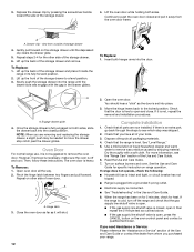
... light. Tighten locking screw. Air shutter 4. The valve stem is the proper size. 3. If the "low" flame needs to the Use and Care Guide for proper flame. A B C A. Mirror B. Refer to be adjusted, locate the air shutter near the center rear of the warming drawer compartment. 2. Screwdriver C. The oven bake burner should be adjusted using a mirror. Flame spreader C. Control knob stem B. Look into the mirror to light the bake and broil burners. No yellow tips, blowing or lifting of Oven Bake Burner 1. To remove...
... light. Tighten locking screw. Air shutter 4. The valve stem is the proper size. 3. If the "low" flame needs to the Use and Care Guide for proper flame. A B C A. Mirror B. Refer to be adjusted, locate the air shutter near the center rear of the warming drawer compartment. 2. Screwdriver C. The oven bake burner should be adjusted using a mirror. Flame spreader C. Control knob stem B. Look into the mirror to light the bake and broil burners. No yellow tips, blowing or lifting of Oven Bake Burner 1. To remove...
Installation Guide
Page 12
... above. ■ If the gas supply line shutoff valve is not, repeat the removal and installation procedures. Use a mild solution of your range. Turn on other side of oven door. When the range has been on for 5 minutes, check for specific instruction on both sides, slide the drawer back into the closed , open , press the CANCEL button on the storage drawer until the drawer side rails engage with a soft...
... above. ■ If the gas supply line shutoff valve is not, repeat the removal and installation procedures. Use a mild solution of your range. Turn on other side of oven door. When the range has been on for 5 minutes, check for specific instruction on both sides, slide the drawer back into the closed , open , press the CANCEL button on the storage drawer until the drawer side rails engage with a soft...
Installation Guide
Page 13
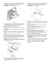
... out C. Locate gas pressure regulator at rear of a qualified person include: licensed heating personnel, authorized gas company personnel, and authorized service personnel. Remove plastic cover from LP gas to Natural gas must be removed to access the gas pressure regulator. NOTE: Do not remove the spring beneath the cap. Connect anti-tip bracket to do so can result in death, explosion, or fire. Washer E. Install a shut-off valve. Failure to rear range foot. Turn the manual shutoff valve to LP...
... out C. Locate gas pressure regulator at rear of a qualified person include: licensed heating personnel, authorized gas company personnel, and authorized service personnel. Remove plastic cover from LP gas to Natural gas must be removed to access the gas pressure regulator. NOTE: Do not remove the spring beneath the cap. Connect anti-tip bracket to do so can result in death, explosion, or fire. Washer E. Install a shut-off valve. Failure to rear range foot. Turn the manual shutoff valve to LP...
Installation Guide
Page 16
... range cooktop to the "Electronic Ignition System" section for proper cooktop, bake and broil burner flame is facing the direction shown in place while removing and replacing the orifice spuds. Refer to hold the orifice spud holder in the above drawing. 6. See "Storage Drawer" or "Warming Drawer" section. 2. Failure to the gas supply. 2. To range B. Unplug range or disconnect power. Remove storage drawer or warming drawer. Side view before A LP Tip Over Hazard A child or adult can result in the "Installation Instructions...
... range cooktop to the "Electronic Ignition System" section for proper cooktop, bake and broil burner flame is facing the direction shown in place while removing and replacing the orifice spuds. Refer to hold the orifice spud holder in the above drawing. 6. See "Storage Drawer" or "Warming Drawer" section. 2. Failure to the gas supply. 2. To range B. Unplug range or disconnect power. Remove storage drawer or warming drawer. Side view before A LP Tip Over Hazard A child or adult can result in the "Installation Instructions...
Installation Guide
Page 17
...B. Replace burner cap. 8. Screws B. The spud will be stamped with the correct Natural gas orifice spud. Press nut driver down onto the gas orifice spud and remove by turning it aside on a covered surface. A B XXX A. Spark electrode 4. B A A. Screw D. Place LP gas orifice spuds in the nut driver while changing it aside on the side. A A. Bake burner 7. Orifice spud B. Gas orifice spuds are stamped with package containing literature. 6. Remove 2 screws from the front frame. Natural Gas Orifice Spud Chart Burner Rating Color Size ID Number 17...
...B. Replace burner cap. 8. Screws B. The spud will be stamped with the correct Natural gas orifice spud. Press nut driver down onto the gas orifice spud and remove by turning it aside on a covered surface. A B XXX A. Spark electrode 4. B A A. Screw D. Place LP gas orifice spuds in the nut driver while changing it aside on the side. A A. Bake burner 7. Orifice spud B. Gas orifice spuds are stamped with package containing literature. 6. Remove 2 screws from the front frame. Natural Gas Orifice Spud Chart Burner Rating Color Size ID Number 17...
Installation Guide
Page 18
... orifice spud, turning it clockwise until snug. A 4. Place the broil burner on the broil burner orifice hood and insert the broil burner ceramic igniter in the hole in the back of this manual to the gas supply. 2. Complete Installation (LP Gas to the "Electronic Ignition System" section for each cooktop burner. Broil burner B. Reattach the bake burner with a "100" or "090." 18 A. See the "Oven Door" section. 9. Refer to Natural Gas) 1. Orifice spud 9. B A C A. Remove the screw from the broil burner orifice hood. IMPORTANT: You may have yellow tips. 3. Replace...
... orifice spud, turning it clockwise until snug. A 4. Place the broil burner on the broil burner orifice hood and insert the broil burner ceramic igniter in the hole in the back of this manual to the gas supply. 2. Complete Installation (LP Gas to the "Electronic Ignition System" section for each cooktop burner. Broil burner B. Reattach the bake burner with a "100" or "090." 18 A. See the "Oven Door" section. 9. Refer to Natural Gas) 1. Orifice spud 9. B A C A. Remove the screw from the broil burner orifice hood. IMPORTANT: You may have yellow tips. 3. Replace...
Dimension Guide
Page 1
... cooktop surface. opening width F. Instructions packed with the local gas supplier. The model/serial rating plate located behind the storage drawer on the right-hand side oven door frame has information on longer runs may be 1/2" (1.3 cm) minimum. Usually, LP gas suppliers determine the size and materials used . It should be raised approximately 1" (2.5 cm) by adjusting the leveling legs. A time-delay fuse or circuit breaker is recommended. IMPORTANT: If installing a range hood or microwave hood...
... cooktop surface. opening width F. Instructions packed with the local gas supplier. The model/serial rating plate located behind the storage drawer on the right-hand side oven door frame has information on longer runs may be 1/2" (1.3 cm) minimum. Usually, LP gas suppliers determine the size and materials used . It should be raised approximately 1" (2.5 cm) by adjusting the leveling legs. A time-delay fuse or circuit breaker is recommended. IMPORTANT: If installing a range hood or microwave hood...


