Installation Instructions
Page 8
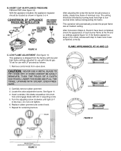
... size. FIGURE 10 C. Carefully remove rubber grommet. 3. Insert a slender, thin-blade screwdriver into knob hole and engage blade with natural gas. The setting should produce a stable, steady blue flame of each step to low several times without extinguishing the flame. Turn the adjusting screw... PRESSURE REGULATOR After adjusting the screw the burner should be located as follows: 1. If the flames appear too large or too small, review each burner flame at medium setting. See figure 11. 4. Replace rubber grommet and control knob. 7. IF KNOB CANNOT BE EASILY REMOVED...
... size. FIGURE 10 C. Carefully remove rubber grommet. 3. Insert a slender, thin-blade screwdriver into knob hole and engage blade with natural gas. The setting should produce a stable, steady blue flame of each step to low several times without extinguishing the flame. Turn the adjusting screw... PRESSURE REGULATOR After adjusting the screw the burner should be located as follows: 1. If the flames appear too large or too small, review each burner flame at medium setting. See figure 11. 4. Replace rubber grommet and control knob. 7. IF KNOB CANNOT BE EASILY REMOVED...