
Installation Instructions
Page 1
U.S.A. Only 4 INSTALLATION INSTRUCTIONS 6 Unpack Range 6 Install Anti-Tip Bracket 6 Electrical Connection - U.S.A. Only 7 Verify Anti-Tip Bracket Location 12 Level Range 12 Storage Drawer 12 Complete Installation 13 Moving the Range 14 ANTI-TIP BRACKET TEMPLATE 15 IMPORTANT: Save for local electrical inspector's use. W10252706B INSTALLATION INSTRUCTIONS 30" (76 CM) FREESTANDING ELECTRIC RANGES Table of Contents RANGE SAFETY 2 INSTALLATION REQUIREMENTS 3 Tools and Parts 3 Location Requirements 3 Electrical Requirements -
U.S.A. Only 4 INSTALLATION INSTRUCTIONS 6 Unpack Range 6 Install Anti-Tip Bracket 6 Electrical Connection - U.S.A. Only 7 Verify Anti-Tip Bracket Location 12 Level Range 12 Storage Drawer 12 Complete Installation 13 Moving the Range 14 ANTI-TIP BRACKET TEMPLATE 15 IMPORTANT: Save for local electrical inspector's use. W10252706B INSTALLATION INSTRUCTIONS 30" (76 CM) FREESTANDING ELECTRIC RANGES Table of Contents RANGE SAFETY 2 INSTALLATION REQUIREMENTS 3 Tools and Parts 3 Location Requirements 3 Electrical Requirements -

Installation Instructions
Page 2
... you how to children and adults. 2 These words mean: DANGER You can be killed or seriously injured if you what can tip the range and be killed or seriously injured if you don't immediately follow instructions. Connect anti-tip bracket to follow the safety alert symbol and either .... This symbol alerts you and others are not followed. Reconnect the anti-tip bracket, if the range is the safety alert symbol. Always read and obey all safety messages. RANGE SAFETY Your safety and the safety of injury, and tell you don't follow instructions. WARNING Tip Over Hazard A ...
... you how to children and adults. 2 These words mean: DANGER You can be killed or seriously injured if you what can tip the range and be killed or seriously injured if you don't immediately follow instructions. Connect anti-tip bracket to follow the safety alert symbol and either .... This symbol alerts you and others are not followed. Reconnect the anti-tip bracket, if the range is the safety alert symbol. Always read and obey all safety messages. RANGE SAFETY Your safety and the safety of injury, and tell you don't follow instructions. WARNING Tip Over Hazard A ...
Installation Instructions
Page 3
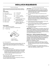
... ¼" nut driver and nut driver 3.2 mm) drill bit (for wood floors) 4.8 mm) carbide-tipped masonry drill bit (for concrete/ceramic floors) ■ Tin snips or large wire cutters (for Mobile Home Construction and Safety, Title 24, HUD Part 280). See "Electrical Requirements...the installer's responsibility to comply with your builder or cabinet supplier to terminal block) ■ 3 - Mobile home installations require: ■ When this range must be installed. See "Electrical Connection" section. 3 Plastic anchors (2) C. #10 x 1¹⁄₂" screws (2) ■ Anti-tip ...
... ¼" nut driver and nut driver 3.2 mm) drill bit (for wood floors) 4.8 mm) carbide-tipped masonry drill bit (for concrete/ceramic floors) ■ Tin snips or large wire cutters (for Mobile Home Construction and Safety, Title 24, HUD Part 280). See "Electrical Requirements...the installer's responsibility to comply with your builder or cabinet supplier to terminal block) ■ 3 - Mobile home installations require: ■ When this range must be installed. See "Electrical Connection" section. 3 Plastic anchors (2) C. #10 x 1¹⁄₂" screws (2) ■ Anti-tip ...
Installation Instructions
Page 4
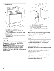
... wire gauge are for dimensional clearances above code standards can be raised approximately 1" (2.5 cm) by adjusting the leveling legs. A freestanding range may be installed next to whether the appliance is recommended that a qualified electrical installer determine that the electrical connection and wire size are ... is used, it will not fit the outlet, have a proper outlet installed by not less than No. 28 MSG sheet steel, 0.015" (0.4 mm) stainless steel, 0.024" (0.6 mm) aluminum or 0.020" (0.5 mm) copper. 30" (76.2 cm) minimum clearance between the top of the cooking platform and...
... wire gauge are for dimensional clearances above code standards can be raised approximately 1" (2.5 cm) by adjusting the leveling legs. A freestanding range may be installed next to whether the appliance is recommended that a qualified electrical installer determine that the electrical connection and wire size are ... is used, it will not fit the outlet, have a proper outlet installed by not less than No. 28 MSG sheet steel, 0.015" (0.4 mm) stainless steel, 0.024" (0.6 mm) aluminum or 0.020" (0.5 mm) copper. 30" (76.2 cm) minimum clearance between the top of the cooking platform and...
Installation Instructions
Page 5
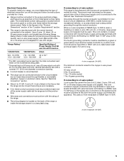
...or an area where local codes prohibit grounding through the neutral conductor is used . For 50-amp rated cord kits, use kits that the range can be connected directly to the circuit breaker box (or fused disconnect) through the neutral, use a 4-wire power supply cord rated at ... line so that specify use with a nominal 1³⁄₈" (34.9 mm) diameter connection opening. ■ A circuit breaker is recommended. ■ The range can be moved if servicing is connected to the cabinet. The fourth (grounding) conductor must be used , a matching UL listed, 4-wire, 250-volt, 40-...
...or an area where local codes prohibit grounding through the neutral conductor is used . For 50-amp rated cord kits, use kits that the range can be connected directly to the circuit breaker box (or fused disconnect) through the neutral, use a 4-wire power supply cord rated at ... line so that specify use with a nominal 1³⁄₈" (34.9 mm) diameter connection opening. ■ A circuit breaker is recommended. ■ The range can be moved if servicing is connected to the cabinet. The fourth (grounding) conductor must be used , a matching UL listed, 4-wire, 250-volt, 40-...
Installation Instructions
Page 6
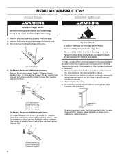
...countertop is not flush with cabinet opening edge, align template with Storage Drawers: Remove the storage drawer. Front leveling leg On Ranges Equipped with Warming Drawers: On ranges equipped with a warming drawer, the rear legs cannot be necessary to lower the rear leveling legs one -half turn ....injury. 1. B A. ¼" drive ratchet B. Do not remove the shipping base at this manual. 2. Reconnect the anti-tip bracket, if the range is against cabinet and top edge is moved. Remove template from the anti-tip bracket kit (found inside oven. 3. Tape template into place. 4. ...
...countertop is not flush with cabinet opening edge, align template with Storage Drawers: Remove the storage drawer. Front leveling leg On Ranges Equipped with Warming Drawers: On ranges equipped with a warming drawer, the rear legs cannot be necessary to lower the rear leveling legs one -half turn ....injury. 1. B A. ¼" drive ratchet B. Do not remove the shipping base at this manual. 2. Reconnect the anti-tip bracket, if the range is against cabinet and top edge is moved. Remove template from the anti-tip bracket kit (found inside oven. 3. Tape template into place. 4. ...

Installation Instructions
Page 7
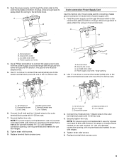
... 10-32 hex nuts from floor. Hex-head screws 7 To mount anti-tip bracket to concrete or ceramic floor, use a 4.8 mm) masonry drill bit to remove cover from range. 3. Longer screws are available from floor. 6. Only Power Supply Cord Direct Wire WARNING WARNING Electrical Shock...wood floor, drill two ¹⁄₈" (3.2 mm) holes at the positions marked on the thickness of the range. Plug into holes with a hammer. Electrically ground range. Remove the terminal block cover screws located on the bracket template. Two mounting tabs each side B. Pull cover ...
... 10-32 hex nuts from floor. Hex-head screws 7 To mount anti-tip bracket to concrete or ceramic floor, use a 4.8 mm) masonry drill bit to remove cover from range. 3. Longer screws are available from floor. 6. Only Power Supply Cord Direct Wire WARNING WARNING Electrical Shock...wood floor, drill two ¹⁄₈" (3.2 mm) holes at the positions marked on the thickness of the range. Plug into holes with a hammer. Electrically ground range. Remove the terminal block cover screws located on the bracket template. Two mounting tabs each side B. Pull cover ...

Installation Instructions
Page 8
...wire is not available) A. Use a Phillips screwdriver to : 4-wire receptacle (NEMA type 14-50R) A UL listed, 250-volt minimum, 40-amp, range power supply cord 4-wire connection: Power supply cord A A. Concuit ■ Tighten strain relief screw against the power supply cord. 4-wire direct ³⁄... prohibit grounding through the neutral 1. Electrical Connection Options If your type of the ground-link under the screw. 8 Part of the range. UL listed strain relief ■ Tighten strain relief screw against the flexible conduit. 3-wire direct ³⁄₈" (1.0 cm)...
...wire is not available) A. Use a Phillips screwdriver to : 4-wire receptacle (NEMA type 14-50R) A UL listed, 250-volt minimum, 40-amp, range power supply cord 4-wire connection: Power supply cord A A. Concuit ■ Tighten strain relief screw against the power supply cord. 4-wire direct ³⁄... prohibit grounding through the neutral 1. Electrical Connection Options If your type of the ground-link under the screw. 8 Part of the range. UL listed strain relief ■ Tighten strain relief screw against the flexible conduit. 3-wire direct ³⁄₈" (1.0 cm)...
Installation Instructions
Page 9
...link screw C. Use a Phillips screwdriver to connect the green ground wire from the power supply cord to the center terminal block post with ranges. 5. UL listed strain relief D. Ground-link screw C. Tighten strain relief screws. 9. Ground-link screw D. Securely tighten hex nuts.... 10-32 hex nuts. A B C D A. Use ³⁄₈" nut driver to connect the neutral (white) wire to the outer terminal block posts with one of range. Line 1 (black) 3. 3. The ground wire must be attached first. 5. Line 2 (red) D D. A F A E B C E A. 10-32 hex nut B. ...
...link screw C. Use a Phillips screwdriver to connect the green ground wire from the power supply cord to the center terminal block post with ranges. 5. UL listed strain relief D. Ground-link screw C. Tighten strain relief screws. 9. Ground-link screw D. Securely tighten hex nuts.... 10-32 hex nuts. A B C D A. Use ³⁄₈" nut driver to connect the neutral (white) wire to the outer terminal block posts with one of range. Line 1 (black) 3. 3. The ground wire must be attached first. 5. Line 2 (red) D D. A F A E B C E A. 10-32 hex nut B. ...

Installation Instructions
Page 10
...chart. A A B B C A. C D E A. Line 2 (red) wire D. Pull the wires through the neutral 1. A B 3" (7.6 cm) 2. Part of range. C G D EF A. Cord/conduit plate D. Loosen (do not remove) the setscrew on your type of electrical supply (4-wire or 3-wire connection). 4-wire Connection: Direct ... to the fuse disconnect or circuit breaker box. Terminal block B. Line 1 (black) wire 4. Direct Wire Installation: Copper or Aluminum Wire This range may be connected directly to the terminal block - 20 lbs-in. (2.3 N-m) Wire Awg Torque 8 gauge copper 6 gauge aluminum 25 lbs-in...
...chart. A A B B C A. C D E A. Line 2 (red) wire D. Pull the wires through the neutral 1. A B 3" (7.6 cm) 2. Part of range. C G D EF A. Cord/conduit plate D. Loosen (do not remove) the setscrew on your type of electrical supply (4-wire or 3-wire connection). 4-wire Connection: Direct ... to the fuse disconnect or circuit breaker box. Terminal block B. Line 1 (black) wire 4. Direct Wire Installation: Copper or Aluminum Wire This range may be connected directly to the terminal block - 20 lbs-in. (2.3 N-m) Wire Awg Torque 8 gauge copper 6 gauge aluminum 25 lbs-in...

Installation Instructions
Page 11
... to the center terminal block post with 10-32 hex nuts. 5. Line 2 (red) C. Attach terminal lugs to the outer terminal block posts with one of range. Use ³⁄₈" nut driver to connect the bare (green) ground wire to the terminal block. Ground-link screw C. Bare (green) ground wire E. Line...
... to the center terminal block post with 10-32 hex nuts. 5. Line 2 (red) C. Attach terminal lugs to the outer terminal block posts with one of range. Use ³⁄₈" nut driver to connect the bare (green) ground wire to the terminal block. Ground-link screw C. Bare (green) ground wire E. Line...

Installation Instructions
Page 12
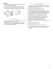
... drawer back approximately 1" (2.5 cm). Place level on some models). Drawer clip 3. Drawer clip - view from outside the range. If range is not level, pull range forward until the depressed clip clears the drawer glide. 5. Check that the anti-tip bracket is under anti-tip bracket. ...2. On models with Warming Drawers: Use a wrench or pliers to view the rear foot from the anti-tip bracket. A Level Range 1. Push range back into position. On Ranges Equipped with a warming drawer, the rear leg cannot be level for removal. A A. Pull the storage drawer forward to back. ...
... drawer back approximately 1" (2.5 cm). Place level on some models). Drawer clip 3. Drawer clip - view from outside the range. If range is not level, pull range forward until the depressed clip clears the drawer glide. 5. Check that the anti-tip bracket is under anti-tip bracket. ...2. On models with Warming Drawers: Use a wrench or pliers to view the rear foot from the anti-tip bracket. A Level Range 1. Push range back into position. On Ranges Equipped with a warming drawer, the rear leg cannot be level for removal. A A. Pull the storage drawer forward to back. ...
Installation Instructions
Page 13
... the drawer back into appropriate outlet. or circuit breaker has not tripped. ■ Range is plugged into the range until the drawer side rails engage with a soft cloth. When the range has been on . 8. A A. If range is an extra part, go back through the steps to move the drawer stop notch... may be needed to see which step was skipped. 2. Complete Installation 1. Check that all of the storage drawer and place it inside the range in the Use and Care Guide. Turn on surface burners and oven. Dispose of the storage drawer to remove waxy residue caused by shipping material...
... the drawer back into appropriate outlet. or circuit breaker has not tripped. ■ Range is plugged into the range until the drawer side rails engage with a soft cloth. When the range has been on . 8. A A. If range is an extra part, go back through the steps to move the drawer stop notch... may be needed to see which step was skipped. 2. Complete Installation 1. Check that all of the storage drawer and place it inside the range in the Use and Care Guide. Turn on surface burners and oven. Dispose of the storage drawer to remove waxy residue caused by shipping material...
Installation Instructions
Page 14
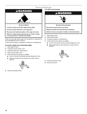
...installed: ■ Look for the anti-tip bracket securely attached to do so can result in death or electrical shock. 1. Slide range forward. 2. Check that anti-tip bracket is level. 14 Complete cleaning or maintenance. 4. Complete cleaning or maintenance. 4. Replace ... before servicing. Disconnect power. 2. Failure to follow these instructions can tip the range and be killed. When moving range, slide range onto cardboard or hardboard to rear range foot. Reconnect power. 6. Check that range is moved. Connect anti-tip bracket to avoid damaging the floor covering. Reconnect...
...installed: ■ Look for the anti-tip bracket securely attached to do so can result in death or electrical shock. 1. Slide range forward. 2. Check that anti-tip bracket is level. 14 Complete cleaning or maintenance. 4. Complete cleaning or maintenance. 4. Replace ... before servicing. Disconnect power. 2. Failure to follow these instructions can tip the range and be killed. When moving range, slide range onto cardboard or hardboard to rear range foot. Reconnect power. 6. Check that range is moved. Connect anti-tip bracket to avoid damaging the floor covering. Reconnect...

Owners Manual
Page 1
...need your model and serial number located on the oven frame behind the storage drawer panel. You will need assistance, call us at www.maytag.com for purchasing this high-quality product. Para obtener acceso a "Instrucciones para el usuario de la estufa eléctrica" en españ...;ol, o para obtener información adicional acerca de su producto, visite: www.maytag.com Tenga listo su número de modelo completo. Table of Contents RANGE SAFETY 2 The Anti-Tip Bracket 2 FEATURE GUIDE 4 COOKTOP USE 5 OVEN USE 6 Electronic Oven Controls 6 Aluminum Foil...
...need your model and serial number located on the oven frame behind the storage drawer panel. You will need assistance, call us at www.maytag.com for purchasing this high-quality product. Para obtener acceso a "Instrucciones para el usuario de la estufa eléctrica" en españ...;ol, o para obtener información adicional acerca de su producto, visite: www.maytag.com Tenga listo su número de modelo completo. Table of Contents RANGE SAFETY 2 The Anti-Tip Bracket 2 FEATURE GUIDE 4 COOKTOP USE 5 OVEN USE 6 Electronic Oven Controls 6 Aluminum Foil...
Owners Manual
Page 2
... messages will not tip during normal use. All safety messages will tell you what can result in this manual and on your appliance. However, the range can tip if you what the potential hazard is, tell you how to reduce the chance of injury, and tell you apply too much force... the antitip bracket fastened down properly. WARNING Tip Over Hazard A child or adult can be killed or seriously injured if you don't immediately follow instructions. RANGE SAFETY Your safety and the safety of others . Always read and obey all safety messages. WARNING You can tip the...
... messages will not tip during normal use. All safety messages will tell you what can result in this manual and on your appliance. However, the range can tip if you what the potential hazard is, tell you how to reduce the chance of injury, and tell you apply too much force... the antitip bracket fastened down properly. WARNING Tip Over Hazard A child or adult can be killed or seriously injured if you don't immediately follow instructions. RANGE SAFETY Your safety and the safety of others . Always read and obey all safety messages. WARNING You can tip the...

Owners Manual
Page 3
...TOUCH SURFACE UNITS OR AREAS NEAR UNITS - The door gasket is properly installed and grounded by a qualified technician. ■ Never Use the Range for range-top service without breaking due to accumulate on hood or filter. ■ When flambeing foods under the hood, turn the fan on hot...location while oven is used in or around any part of the range. ■ Wear Proper Apparel - Surface units may penetrate the broken cooktop and create a risk of electric shock. Only certain types of glass, glass/ceramic, ceramic, earthenware, or other servicing should be taken not to line ...
...TOUCH SURFACE UNITS OR AREAS NEAR UNITS - The door gasket is properly installed and grounded by a qualified technician. ■ Never Use the Range for range-top service without breaking due to accumulate on hood or filter. ■ When flambeing foods under the hood, turn the fan on hot...location while oven is used in or around any part of the range. ■ Wear Proper Apparel - Surface units may penetrate the broken cooktop and create a risk of electric shock. Only certain types of glass, glass/ceramic, ceramic, earthenware, or other servicing should be taken not to line ...

Owners Manual
Page 4
...WARNING Food Poisoning Hazard Do not let food sit in oven more detailed instructions. See the "Range Care" section. 1. Only the CLOCK, OVEN LIGHT, and KITCHEN TIMER keypads will sound at www.maytag.com for the change the temperature repeat Step 2. Press KITCHEN TIMER. 2. Press START to... light Self-clean cycle Oven control lockout Clock Oven timer Baking and roasting Broiling INSTRUCTIONS The oven light may have some or all of the range. Check that the oven is opened. Press TEMP/TIME "+" or "-" keypads to display the countdown for 3 seconds. 3. Press START. 4. Press BROIL...
...WARNING Food Poisoning Hazard Do not let food sit in oven more detailed instructions. See the "Range Care" section. 1. Only the CLOCK, OVEN LIGHT, and KITCHEN TIMER keypads will sound at www.maytag.com for the change the temperature repeat Step 2. Press KITCHEN TIMER. 2. Press START to... light Self-clean cycle Oven control lockout Clock Oven timer Baking and roasting Broiling INSTRUCTIONS The oven light may have some or all of the range. Check that the oven is opened. Press TEMP/TIME "+" or "-" keypads to display the countdown for 3 seconds. 3. Press START. 4. Press BROIL...
Owners Manual
Page 5
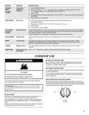
...turned off all controls when done cooking. It may become hot. Single 5 Press CANCEL when finished. Hot Surface Indicator Light On ceramic glass models, the hot surface indicator light is on. The hot surface indicator light will glow red when an element is located on... 4. Failure to do so can be used to adjust time and temperature settings. Press CANCEL when finished. If start Range function Temperature and time adjust INSTRUCTIONS 1. Ceramic Glass The surface cooking area will glow as long as a regular element. Cookware should not be used to enter the ...
...turned off all controls when done cooking. It may become hot. Single 5 Press CANCEL when finished. Hot Surface Indicator Light On ceramic glass models, the hot surface indicator light is on. The hot surface indicator light will glow red when an element is located on... 4. Failure to do so can be used to adjust time and temperature settings. Press CANCEL when finished. If start Range function Temperature and time adjust INSTRUCTIONS 1. Ceramic Glass The surface cooking area will glow as long as a regular element. Cookware should not be used to enter the ...

Owners Manual
Page 7
... on when the oven door is opened during preheat and bake to the cover for 2-rack baking and broiling. Please refer to maintain a precise temperature range for baking. and layer cakes. A. This feature is automatically activated when the oven is pressed, the oven will come back on 2 racks use a broiler pan...
... on when the oven door is opened during preheat and bake to the cover for 2-rack baking and broiling. Please refer to maintain a precise temperature range for baking. and layer cakes. A. This feature is automatically activated when the oven is pressed, the oven will come back on 2 racks use a broiler pan...


