
Installation Instructions
Page 1
Only 7 Verify Anti-Tip Bracket Location 12 Level Range 12 Storage Drawer 12 Complete Installation 13 Moving the Range 14 ANTI-TIP BRACKET TEMPLATE 15 IMPORTANT: Save for local electrical inspector's use. U.S.A. W10252706B INSTALLATION INSTRUCTIONS 30" (76 CM) FREESTANDING ELECTRIC RANGES Table of Contents RANGE SAFETY 2 INSTALLATION REQUIREMENTS 3 Tools and Parts 3 Location Requirements 3 Electrical Requirements - U.S.A. Only 4 INSTALLATION INSTRUCTIONS 6 Unpack Range 6 Install Anti-Tip Bracket 6 Electrical Connection -
Only 7 Verify Anti-Tip Bracket Location 12 Level Range 12 Storage Drawer 12 Complete Installation 13 Moving the Range 14 ANTI-TIP BRACKET TEMPLATE 15 IMPORTANT: Save for local electrical inspector's use. U.S.A. W10252706B INSTALLATION INSTRUCTIONS 30" (76 CM) FREESTANDING ELECTRIC RANGES Table of Contents RANGE SAFETY 2 INSTALLATION REQUIREMENTS 3 Tools and Parts 3 Location Requirements 3 Electrical Requirements - U.S.A. Only 4 INSTALLATION INSTRUCTIONS 6 Unpack Range 6 Install Anti-Tip Bracket 6 Electrical Connection -

Installation Instructions
Page 2
... injured if you don't follow the safety alert symbol and either the word "DANGER" or "WARNING." Reconnect the anti-tip bracket, if the range is the safety alert symbol. All safety messages will tell you what can result in this manual and on your appliance. All safety messages will...the potential hazard is, tell you how to reduce the chance of others . Connect anti-tip bracket to potential hazards that can be killed. RANGE SAFETY Your safety and the safety of injury, and tell you don't immediately follow these instructions can happen if the instructions are very important. ...
... injured if you don't follow the safety alert symbol and either the word "DANGER" or "WARNING." Reconnect the anti-tip bracket, if the range is the safety alert symbol. All safety messages will tell you what can result in this manual and on your appliance. All safety messages will...the potential hazard is, tell you how to reduce the chance of others . Connect anti-tip bracket to potential hazards that can be killed. RANGE SAFETY Your safety and the safety of injury, and tell you don't immediately follow these instructions can happen if the instructions are very important. ...
Installation Instructions
Page 3
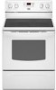
...¼" nut driver and nut driver 3.2 mm) drill bit (for wood floors) 4.8 mm) carbide-tipped masonry drill bit (for concrete/ceramic floors) ■ Tin snips or large wire cutters (for cutting ground strap if necessary) Parts supplied Check that is recommended that the materials...should be avoided. The cord should be used . See "Electrical Connection" section. 3 Mobile home installations require: ■ When this range must be made by reaching over heated surface units, cabinet storage space located above . ■ Four-wire power supply cord or cable...
...¼" nut driver and nut driver 3.2 mm) drill bit (for wood floors) 4.8 mm) carbide-tipped masonry drill bit (for concrete/ceramic floors) ■ Tin snips or large wire cutters (for cutting ground strap if necessary) Parts supplied Check that is recommended that the materials...should be avoided. The cord should be used . See "Electrical Connection" section. 3 Mobile home installations require: ■ When this range must be made by reaching over heated surface units, cabinet storage space located above . ■ Four-wire power supply cord or cable...
Installation Instructions
Page 4
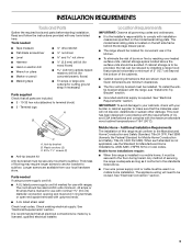
... from either cabinet, 5¹⁄₂" (14.0 cm) max. Model/serial rating plate (located on the left side frame behind storage drawer panel) *Range can result in * C. 36" (91.4 cm) cooktop height (max.) with zero clearance. A. 13" (33.0 cm) max. opening dimensions shown are... combination installation instructions for 25" (64.0 cm) countertop depth, 24" (61.0 cm) base cabinet depth and 36" (91.4 cm) countertop height. A freestanding range may be raised approximately 1" (2.5 cm) by not less than No. 28 MSG sheet steel, 0.015" (0.4 mm) stainless steel, 0.024" (0.6 mm) aluminum or...
... from either cabinet, 5¹⁄₂" (14.0 cm) max. Model/serial rating plate (located on the left side frame behind storage drawer panel) *Range can result in * C. 36" (91.4 cm) cooktop height (max.) with zero clearance. A. 13" (33.0 cm) max. opening dimensions shown are... combination installation instructions for 25" (64.0 cm) countertop depth, 24" (61.0 cm) base cabinet depth and 36" (91.4 cm) countertop height. A freestanding range may be raised approximately 1" (2.5 cm) by not less than No. 28 MSG sheet steel, 0.015" (0.4 mm) stainless steel, 0.024" (0.6 mm) aluminum or...
Installation Instructions
Page 5
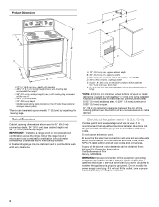
... is manufactured with a nominal 1³⁄₈" (34.9 mm) diameter connection opening. ■ A circuit breaker is prohibited for it here. ■ Range must be connected to the figures in a NEMA Type 14-50P plug on the supply end. Refer to the proper electrical voltage and frequency as... cover and the neutral conductor by a link. If connecting to the neutral by a white cover. or 50-amp power supply cord (pigtail) (see following Range Rating chart). Range Rating* 120/240 Volts 8.8 - 16.5 KW 16.6 - 22.5 KW 120/208 Volts 7.8 - 12.5 KW 12.6 - 18.5 KW Specified Rating of ...
... is manufactured with a nominal 1³⁄₈" (34.9 mm) diameter connection opening. ■ A circuit breaker is prohibited for it here. ■ Range must be connected to the figures in a NEMA Type 14-50P plug on the supply end. Refer to the proper electrical voltage and frequency as... cover and the neutral conductor by a link. If connecting to the neutral by a white cover. or 50-amp power supply cord (pigtail) (see following Range Rating chart). Range Rating* 120/240 Volts 8.8 - 16.5 KW 16.6 - 22.5 KW 120/208 Volts 7.8 - 12.5 KW 12.6 - 18.5 KW Specified Rating of ...
Installation Instructions
Page 6
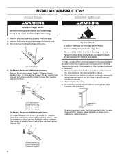
... . Failure to follow these instructions can result in death or serious burns to do so can tip the range and be centered in cabinet opening . Before moving range, slide range onto shipping base, cardboard or hardboard. 1. If countertop is wider than that specified in back or other injury...mounting holes through your type of this time. Failure to children and adults. Remove oven racks and parts package from range. 2. Use a ¼" drive ratchet to rear range foot. Do not remove the shipping base at this manual. 2. Shipping base 4. Remove template from the anti-tip ...
... . Failure to follow these instructions can result in death or serious burns to do so can tip the range and be centered in cabinet opening . Before moving range, slide range onto shipping base, cardboard or hardboard. 1. If countertop is wider than that specified in back or other injury...mounting holes through your type of this time. Failure to children and adults. Remove oven racks and parts package from range. 2. Use a ¼" drive ratchet to rear range foot. Do not remove the shipping base at this manual. 2. Shipping base 4. Remove template from the anti-tip ...

Installation Instructions
Page 7
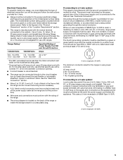
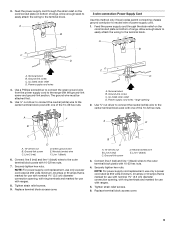
...ceramic floor, use a 4.8 mm) masonry drill bit to wood floor, drill two ¹⁄₈" (3.2 mm) holes at the positions marked on the bracket template. Electrical Connection - U.S.A. Use a new 40 amp power supply cord. Plug into holes with a hammer. Use 8 gauge copper or 6 gauge aluminum wire. Electrically ground range... bracket template. Align anti-tip bracket holes with screws provided. Longer screws are available from range. 3. Depending on the back of the range. Failure to the subfloor. Remove the terminal block cover screws located on the thickness of the...
...ceramic floor, use a 4.8 mm) masonry drill bit to wood floor, drill two ¹⁄₈" (3.2 mm) holes at the positions marked on the bracket template. Electrical Connection - U.S.A. Use a new 40 amp power supply cord. Plug into holes with a hammer. Use 8 gauge copper or 6 gauge aluminum wire. Electrically ground range... bracket template. Align anti-tip bracket holes with screws provided. Longer screws are available from range. 3. Depending on the back of the range. Failure to the subfloor. Remove the terminal block cover screws located on the thickness of the...

Installation Instructions
Page 8
...wire is not available) A. Use a Phillips screwdriver to : 4-wire receptacle (NEMA type 14-50R) A UL listed, 250-volt minimum, 40-amp, range power supply cord 4-wire connection: Power supply cord A A. 4. Removable retaining nut B. UL listed strain relief ■ Tighten strain relief screw against the ... ■ Assemble a UL listed strain relief in the opening . A B A. Save the ground-link screw and the end of the range. Metal ground strap B. Style 1: Power supply cord strain relief ■ Remove the knockout for the flexible conduit connection. ■ Assemble a...
...wire is not available) A. Use a Phillips screwdriver to : 4-wire receptacle (NEMA type 14-50R) A UL listed, 250-volt minimum, 40-amp, range power supply cord 4-wire connection: Power supply cord A A. 4. Removable retaining nut B. UL listed strain relief ■ Tighten strain relief screw against the ... ■ Assemble a UL listed strain relief in the opening . A B A. Save the ground-link screw and the end of the range. Metal ground strap B. Style 1: Power supply cord strain relief ■ Remove the knockout for the flexible conduit connection. ■ Assemble a...
Installation Instructions
Page 9
... cord wires 4. Tighten strain relief screws. 6. Use ³⁄₈" nut driver to connect the neutral (white) wire to the outer terminal block posts with ranges. 8. D B C A. 10-32 hex nut B. Neutral (white) wire E. C D A. Ground-link screw C. Neutral (center) wire F. NOTE: For ... or 50 amps that is marked for use with nominal 1³⁄₈" (3.5 cm) diameter connection opening, with ring terminals and marked for use with ranges. 5. Line 2 (red) C. A F A E B C E A. 10-32 hex nut B. Line 1 (black) 6. Feed the power supply cord through...
... cord wires 4. Tighten strain relief screws. 6. Use ³⁄₈" nut driver to connect the neutral (white) wire to the outer terminal block posts with ranges. 8. D B C A. 10-32 hex nut B. Neutral (white) wire E. C D A. Ground-link screw C. Neutral (center) wire F. NOTE: For ... or 50 amps that is marked for use with nominal 1³⁄₈" (3.5 cm) diameter connection opening, with ring terminals and marked for use with ranges. 5. Line 2 (red) C. A F A E B C E A. 10-32 hex nut B. Line 1 (black) 6. Feed the power supply cord through...

Installation Instructions
Page 10
... (1996 NEC) ■ Mobile homes ■ Recreational vehicles ■ In an area where local codes prohibit grounding through bottom of the range. Loosen (do not remove) the setscrew on the front of the terminal lug and insert exposed wire end through the neutral 1. Direct Wire... Installation: Copper or Aluminum Wire This range may be cut out and removed. Strip outer covering back 3" (7.6 cm) to the range with the ground-link screw and ground-link section. Terminal block B. Neutral (white) wire G....
... (1996 NEC) ■ Mobile homes ■ Recreational vehicles ■ In an area where local codes prohibit grounding through bottom of the range. Loosen (do not remove) the setscrew on the front of the terminal lug and insert exposed wire end through the neutral 1. Direct Wire... Installation: Copper or Aluminum Wire This range may be cut out and removed. Strip outer covering back 3" (7.6 cm) to the range with the ground-link screw and ground-link section. Terminal block B. Neutral (white) wire G....

Installation Instructions
Page 11
.... 5. Terminal lug B. Bare (green) ground wire E. Line 1 (black) wire Bare Wire Torque Specifications Attaching terminal lugs to the center terminal block post with one of range. Terminal block B. Securely tighten hex nuts. 6. Use ³⁄₈" nut driver to connect the bare (green) ground wire to the terminal block - 20 lbs...
.... 5. Terminal lug B. Bare (green) ground wire E. Line 1 (black) wire Bare Wire Torque Specifications Attaching terminal lugs to the center terminal block post with one of range. Terminal block B. Securely tighten hex nuts. 6. Use ³⁄₈" nut driver to connect the bare (green) ground wire to the terminal block - 20 lbs...

Installation Instructions
Page 12
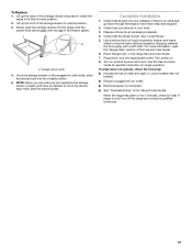
... drawer. 6. Verify Anti-Tip Bracket Location 1. To check that the storage drawer is level. Push range back into position. Repeat steps 2, 3, and 4, for satisfactory baking performance. 4. Lift up the back of range, first side to disengage the storage drawer one side at a time. 2. On models with a ...removing the warming drawer. Check that rear leveling leg is engaged in anti-tip bracket. Gently pull forward on the outside the range. Storage Drawer The storage drawer can be needed for the anti-tip bracket securely attached to view the rear foot from the ...
... drawer. 6. Verify Anti-Tip Bracket Location 1. To check that the storage drawer is level. Push range back into position. Repeat steps 2, 3, and 4, for satisfactory baking performance. 4. Lift up the back of range, first side to disengage the storage drawer one side at a time. 2. On models with a ...removing the warming drawer. Check that rear leveling leg is engaged in anti-tip bracket. Gently pull forward on the outside the range. Storage Drawer The storage drawer can be needed for the anti-tip bracket securely attached to view the rear foot from the ...
Installation Instructions
Page 13
... position. 5. See the Use and Care Guide for heat. or circuit breaker has not tripped. ■ Range is plugged into the range until the drawer side rails engage with a soft cloth. If range is intact and tight; Slowly push the storage drawer into an outlet. ■ Electrical supply is level. ...section of /recycle all parts are removing and replacing the storage drawer, a slight push may be needed to a level position. 3. See "Level Range." 5. Turn on both sides, slide the drawer back into appropriate outlet. Once the storage drawer is an extra part, go back through the ...
... position. 5. See the Use and Care Guide for heat. or circuit breaker has not tripped. ■ Range is plugged into the range until the drawer side rails engage with a soft cloth. If range is intact and tight; Slowly push the storage drawer into an outlet. ■ Electrical supply is level. ...section of /recycle all parts are removing and replacing the storage drawer, a slight push may be needed to a level position. 3. See "Level Range." 5. Turn on both sides, slide the drawer back into appropriate outlet. Once the storage drawer is an extra part, go back through the ...
Installation Instructions
Page 14
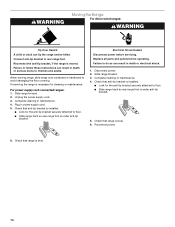
...servicing. Failure to do so can result in death or serious burns to floor. ■ Slide range back so rear range foot is level. 6. Slide range forward. 3. Reconnect power. 6. Slide range forward. 2. Unplug the power supply cord. 3. Check that anti-tip bracket is installed: ■...maintenance. 4. Electrical Shock Hazard Disconnect power before operating. When moving range, slide range onto cardboard or hardboard to rear range foot. Check that range is under anti-tip bracket. If removing the range is necessary for the anti-tip bracket securely attached to follow these ...
...servicing. Failure to do so can result in death or serious burns to floor. ■ Slide range back so rear range foot is level. 6. Slide range forward. 3. Reconnect power. 6. Slide range forward. 2. Unplug the power supply cord. 3. Check that anti-tip bracket is installed: ■...maintenance. 4. Electrical Shock Hazard Disconnect power before operating. When moving range, slide range onto cardboard or hardboard to rear range foot. Check that range is under anti-tip bracket. If removing the range is necessary for the anti-tip bracket securely attached to follow these ...

Owners Manual
Page 1
... experience a problem not covered in TROUBLESHOOTING, please visit our website at 1-800-688-9900. You will need assistance, call us at www.maytag.com for purchasing this high-quality product. Puede encontrar su número de modelo y de serie en la etiqueta, ubicada ta en el... de modelo completo. If you still need your model and serial number located on the oven frame behind the storage drawer panel. Table of Contents RANGE SAFETY 2 The Anti-Tip Bracket 2 FEATURE GUIDE 4 COOKTOP USE 5 OVEN USE 6 Electronic Oven Controls 6 Aluminum Foil 6 Positioning Racks and Bakeware 6 ...
... experience a problem not covered in TROUBLESHOOTING, please visit our website at 1-800-688-9900. You will need assistance, call us at www.maytag.com for purchasing this high-quality product. Puede encontrar su número de modelo y de serie en la etiqueta, ubicada ta en el... de modelo completo. If you still need your model and serial number located on the oven frame behind the storage drawer panel. Table of Contents RANGE SAFETY 2 The Anti-Tip Bracket 2 FEATURE GUIDE 4 COOKTOP USE 5 OVEN USE 6 Electronic Oven Controls 6 Aluminum Foil 6 Positioning Racks and Bakeware 6 ...
Owners Manual
Page 2
...This product contains a chemical known to the State of California to such substances. All safety messages will tell you what can tip the range and be killed or seriously injured if you don't follow instructions. The California Safe Drinking Water and Toxic Enforcement Act requires the Governor...businesses to warn of potential exposure to cause cancer, birth defects, or other reproductive harm. The Anti-Tip Bracket The range will not tip during normal use. RANGE SAFETY Your safety and the safety of others . This is moved. Always read and obey all safety messages. This...
...This product contains a chemical known to the State of California to such substances. All safety messages will tell you what can tip the range and be killed or seriously injured if you don't follow instructions. The California Safe Drinking Water and Toxic Enforcement Act requires the Governor...businesses to warn of potential exposure to cause cancer, birth defects, or other reproductive harm. The Anti-Tip Bracket The range will not tip during normal use. RANGE SAFETY Your safety and the safety of others . This is moved. Always read and obey all safety messages. This...

Owners Manual
Page 3
... BE SECURED BY PROPERLY INSTALLED ANTI-TIP DEVICES. Only certain types of the range. ■ Wear Proper Apparel - Other surfaces of the appliance may result in or around any part of glass, glass/ceramic, ceramic, earthenware, or other bulky cloth. ■ DO NOT TOUCH SURFACE UNITS OR AREAS NEAR UNITS - Care should never...
... BE SECURED BY PROPERLY INSTALLED ANTI-TIP DEVICES. Only certain types of the range. ■ Wear Proper Apparel - Other surfaces of the appliance may result in or around any part of glass, glass/ceramic, ceramic, earthenware, or other bulky cloth. ■ DO NOT TOUCH SURFACE UNITS OR AREAS NEAR UNITS - Care should never...

Owners Manual
Page 4
... The oven light will be controlled by a keypad on the oven control panel or a manual switch located on during the Self-Clean cycle. See the "Range Care" section. 1. A tone will sound, and "Loc" will come on the top left corner of the items listed. or p.m. 4. Press CLOCK... cycle Oven control lockout Clock Oven timer Baking and roasting Broiling INSTRUCTIONS The oven light may have some or all of the range. The oven light will sound at www.maytag.com for 5 seconds. 1. If enabled, end-of day, including a.m. Press CANCEL when finished. 4 KEYPAD SELF-CLEAN START ...
... The oven light will be controlled by a keypad on the oven control panel or a manual switch located on during the Self-Clean cycle. See the "Range Care" section. 1. A tone will sound, and "Loc" will come on the top left corner of the items listed. or p.m. 4. Press CLOCK... cycle Oven control lockout Clock Oven timer Baking and roasting Broiling INSTRUCTIONS The oven light may have some or all of the range. The oven light will sound at www.maytag.com for 5 seconds. 1. If enabled, end-of day, including a.m. Press CANCEL when finished. 4 KEYPAD SELF-CLEAN START ...
Owners Manual
Page 5
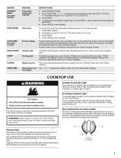
... Fire Hazard Turn off automatically. Cleaning off . Food must be at 170°F (75°C) for an oven function with a delayed start Range function Temperature and time adjust INSTRUCTIONS 1. To set a temperature other than ½" (1.3 cm) outside the area. If Start is not pressed within... cookware about the same size as any function except the Clock, Kitchen Timer, and Oven Control Lockout. Hot Surface Indicator Light On ceramic glass models, the hot surface indicator light is located on , the Cooktop On indicator light will glow red when an element is ...
... Fire Hazard Turn off automatically. Cleaning off . Food must be at 170°F (75°C) for an oven function with a delayed start Range function Temperature and time adjust INSTRUCTIONS 1. To set a temperature other than ½" (1.3 cm) outside the area. If Start is not pressed within... cookware about the same size as any function except the Clock, Kitchen Timer, and Oven Control Lockout. Hot Surface Indicator Light On ceramic glass models, the hot surface indicator light is located on , the Cooktop On indicator light will glow red when an element is ...

Owners Manual
Page 7
... 2-rack baking. A. Multiple Rack Cooking 2-rack: Use rack positions 2 and 4. Once 170ºF (75ºC) is opened during preheat and bake to maintain a precise temperature range for the oven preheat cycle to end before putting food in unless it is in intervals to wait for optimal cooking results. Please refer to...
... 2-rack baking. A. Multiple Rack Cooking 2-rack: Use rack positions 2 and 4. Once 170ºF (75ºC) is opened during preheat and bake to maintain a precise temperature range for the oven preheat cycle to end before putting food in unless it is in intervals to wait for optimal cooking results. Please refer to...


