
Installation Instructions
Page 2
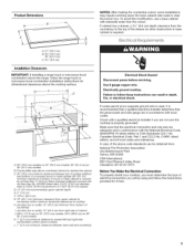
... are minimum clearances and provide 0" (0 cm) clearance. • Grounded electrical supply is approved. Tools needed • Tape measure • Phillips head screwdriver • Marker or pencil • Pliers Parts supplied • 1" (2.54 cm) mounting screws (4) Parts needed • A UL listed or CSA approved conduit connector • UL listed wire connectors Check local codes. IMPORTANT: To avoid damage to countertop with your cooktop model number and approved combinations of cooktops and ovens...
... are minimum clearances and provide 0" (0 cm) clearance. • Grounded electrical supply is approved. Tools needed • Tape measure • Phillips head screwdriver • Marker or pencil • Pliers Parts supplied • 1" (2.54 cm) mounting screws (4) Parts needed • A UL listed or CSA approved conduit connector • UL listed wire connectors Check local codes. IMPORTANT: To avoid damage to countertop with your cooktop model number and approved combinations of cooktops and ovens...
Installation Instructions
Page 3
... range, follow the range hood or microwave hood combination installation instructions for dimensional clearances above ) C. 30" (76.2 cm) minimum clearance between top of the drawer (or other obstruction) in base cabinet is required. G A. 30" (76.2cm) models on 30" (76.2 cm) models; 36" (91.4 cm) on 36" (91.4 cm) models B. To avoid this modification, use a base cabinet with sidewalls wider than the cutout. Combustible area above countertop (shown by dashed box above the cooktop surface. If cabinet...
... range, follow the range hood or microwave hood combination installation instructions for dimensional clearances above ) C. 30" (76.2 cm) minimum clearance between top of the drawer (or other obstruction) in base cabinet is required. G A. 30" (76.2cm) models on 30" (76.2 cm) models; 36" (91.4 cm) on 36" (91.4 cm) models B. To avoid this modification, use a base cabinet with sidewalls wider than the cutout. Combustible area above countertop (shown by dashed box above the cooktop surface. If cabinet...

Installation Instructions
Page 4
... be connected directly to avoid scratching the countertop. Remove the coil elements and burner bowls. • Push in the edge of solid copper wire to move and install cooktop. If repositioning is needed , lift entire cooktop up from cutout to the junction box through flexible, armored or nonmetallic sheathed, copper cable. Connect the aluminum wiring to avoid scratching the countertop. If repositioning is needed , lift entire cooktop up from cutout...
... be connected directly to avoid scratching the countertop. Remove the coil elements and burner bowls. • Push in the edge of solid copper wire to move and install cooktop. If repositioning is needed , lift entire cooktop up from cutout to the junction box through flexible, armored or nonmetallic sheathed, copper cable. Connect the aluminum wiring to avoid scratching the countertop. If repositioning is needed , lift entire cooktop up from cutout...

Installation Instructions
Page 5
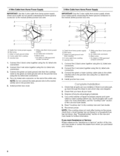
... the cooktop base to countertop with the coil element receptacle. \ Holding the coil element as level as it will be connecting to: 4-wire A fused disconnect or Go to Section: 4-Wire Cable from Home Power (12.7 cm) cbiorcxuit breaker Supply 3-wire 1" (2.5 c m}_,, A fused disconnect or circuit breaker box 3-Wire Cable from the cooktop to the junction box using the 4 screws. 9. Replace the coil elements and burner bowls. • Line up openings in the burner bowl with the 4 mounting screws. 8. Use...
... the cooktop base to countertop with the coil element receptacle. \ Holding the coil element as level as it will be connecting to: 4-wire A fused disconnect or Go to Section: 4-Wire Cable from Home Power (12.7 cm) cbiorcxuit breaker Supply 3-wire 1" (2.5 c m}_,, A fused disconnect or circuit breaker box 3-Wire Cable from the cooktop to the junction box using the 4 screws. 9. Replace the coil elements and burner bowls. • Line up openings in the burner bowl with the 4 mounting screws. 8. Use...
Installation Instructions
Page 6
... "Cooktop Care" section of the white wire. If you need Assistance or Service: Please reference the "Assistance or Service" section of the Use and Care Guide or contact the dealer from whom you have all your cooktop. 6 Connect the 2 red wires together using the UL listed wire connectors. 3. Install junction box cover. Install junction box cover. Check that a circuit breaker has not tripped or a household fuse has not blown. NOTE: If the cooktop does not work after turning...
... "Cooktop Care" section of the white wire. If you need Assistance or Service: Please reference the "Assistance or Service" section of the Use and Care Guide or contact the dealer from whom you have all your cooktop. 6 Connect the 2 red wires together using the UL listed wire connectors. 3. Install junction box cover. Install junction box cover. Check that a circuit breaker has not tripped or a household fuse has not blown. NOTE: If the cooktop does not work after turning...


