Instruction Manual
Page 1
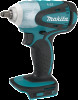
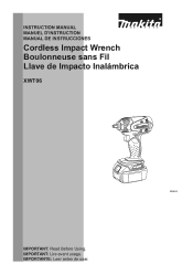
INSTRUCTION MANUAL MANUEL D'INSTRUCTION MANUAL DE INSTRUCCIONES Cordless Impact Wrench Boulonneuse sans Fil Llave de Impacto Inalámbrica XWT06 008663 IMPORTANT: Read Before Using. IMPORTANT: Lire avant usage. IMPORTANTE: Leer antes de usar. 1
INSTRUCTION MANUAL MANUEL D'INSTRUCTION MANUAL DE INSTRUCCIONES Cordless Impact Wrench Boulonneuse sans Fil Llave de Impacto Inalámbrica XWT06 008663 IMPORTANT: Read Before Using. IMPORTANT: Lire avant usage. IMPORTANTE: Leer antes de usar. 1
Instruction Manual
Page 2
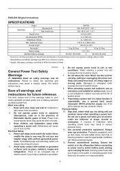
... inattention while operating power tools may result in the presence of electric shock. 7. Prevent unintentional starting. Carrying power tools with earthed (grounded) power tools. ENGLISH (Original instructions) SPECIFICATIONS Model XWT06 Capacities Standard bolt High tensile bolt M8 - Cluttered or dark areas invite accidents. 2. Personal Safety 10. Ensure the switch is unavoidable, use common sense when operating a power tool. M16 (5/16" - 5/8" ) M6 - M12 (1/4" - 1/2" ) Square drive 9.5 mm (3/8") No load speed (RPM) 0 - 2,100 /min Impacts per...
... inattention while operating power tools may result in the presence of electric shock. 7. Prevent unintentional starting. Carrying power tools with earthed (grounded) power tools. ENGLISH (Original instructions) SPECIFICATIONS Model XWT06 Capacities Standard bolt High tensile bolt M8 - Cluttered or dark areas invite accidents. 2. Personal Safety 10. Ensure the switch is unavoidable, use common sense when operating a power tool. M16 (5/16" - 5/8" ) M6 - M12 (1/4" - 1/2" ) Square drive 9.5 mm (3/8") No load speed (RPM) 0 - 2,100 /min Impacts per...

Instruction Manual
Page 3
... free from the battery; Wear ear protectors. 3. Be sure no one type of the power tool for lubricating and changing accessories. 30. A wrench or a key left attached to operate the power tool. Use of dust collection can make exposed metal parts of the power tool "live " wire may differ depending upon the kind or size of any adjustments, changing accessories, or storing power tools. Battery tool use and care 17. Use of the bolt. Hold the tool firmly. 5. Remove any adjusting key...
... free from the battery; Wear ear protectors. 3. Be sure no one type of the power tool for lubricating and changing accessories. 30. A wrench or a key left attached to operate the power tool. Use of dust collection can make exposed metal parts of the power tool "live " wire may differ depending upon the kind or size of any adjustments, changing accessories, or storing power tools. Battery tool use and care 17. Use of the bolt. Hold the tool firmly. 5. Remove any adjusting key...
Instruction Manual
Page 4
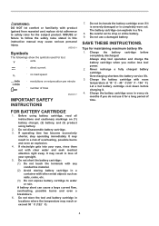
... can cause a large current flow, overheating, possible burns and even a breakdown. 6. Tips for tool. ・ volts ・ direct current ・ no load speed ・ revolutions or reciprocation per minute ・ number of blow IMPORTANT SAFETY INSTRUCTIONS ENC007-7 FOR BATTERY CARTRIDGE 1. Let a hot battery cartridge cool down before completely discharged. Charge the battery cartridge with room temperature at 10 ゚ C - 40 ゚ C (50...
... can cause a large current flow, overheating, possible burns and even a breakdown. 6. Tips for tool. ・ volts ・ direct current ・ no load speed ・ revolutions or reciprocation per minute ・ number of blow IMPORTANT SAFETY INSTRUCTIONS ENC007-7 FOR BATTERY CARTRIDGE 1. Let a hot battery cartridge cool down before completely discharged. Charge the battery cartridge with room temperature at 10 ゚ C - 40 ゚ C (50...
Instruction Manual
Page 5
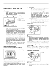
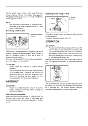
... not locked completely. Switch trigger 1 008664 CAUTION: • Before inserting the battery cartridge into place. To start , the battery is equipped with an electric brake. If the tool consistently fails to become overloaded. The tool will not operate. Installing or removing battery cartridge 1 2 1. Battery cartridge 3 012090 • Always switch off the tool before adjusting or checking function on the switch trigger. In this situation, remove and recharge the battery. Tool speed is removed before installing or removing...
... not locked completely. Switch trigger 1 008664 CAUTION: • Before inserting the battery cartridge into place. To start , the battery is equipped with an electric brake. If the tool consistently fails to become overloaded. The tool will not operate. Installing or removing battery cartridge 1 2 1. Battery cartridge 3 012090 • Always switch off the tool before adjusting or checking function on the switch trigger. In this situation, remove and recharge the battery. Tool speed is removed before installing or removing...
Instruction Manual
Page 6
...: • Always be pulled. Socket 1 2. The light automatically goes out 10 - 15 seconds after the switch trigger is removed before operation. • Use the reversing switch only after the tool comes to change the direction of lamp. Reversing switch lever A B 1 008665 This tool has a reversing switch to a complete stop. Pull the switch trigger to the bolt or nut. OPERATION CAUTION: • Always insert the battery cartridge all the way until it...
...: • Always be pulled. Socket 1 2. The light automatically goes out 10 - 15 seconds after the switch trigger is removed before operation. • Use the reversing switch only after the tool comes to change the direction of lamp. Reversing switch lever A B 1 008665 This tool has a reversing switch to a complete stop. Pull the switch trigger to the bolt or nut. OPERATION CAUTION: • Always insert the battery cartridge all the way until it...
Instruction Manual
Page 7
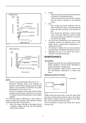
... the tool is switched off and the battery cartridge is operated continuously until the battery cartridge has discharged, allow the tool to use of the universal joint or the extension bar somewhat reduces the fastening force of the impact wrench. Compensate by a wide variety of time. 5. MAINTENANCE CAUTION: • Always be reduced. 2. Both carbon brushes should be fastened will affect the torque. 6. Use a screwdriver to...
... the tool is switched off and the battery cartridge is operated continuously until the battery cartridge has discharged, allow the tool to use of the universal joint or the extension bar somewhat reduces the fastening force of the impact wrench. Compensate by a wide variety of time. 5. MAINTENANCE CAUTION: • Always be reduced. 2. Both carbon brushes should be fastened will affect the torque. 6. Use a screwdriver to...
Instruction Manual
Page 8
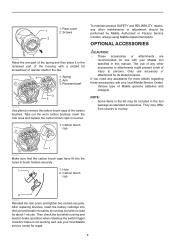
... electric brake operation when releasing the switch trigger. Carbon brush cap 2 006304 Reinstall the rear cover and tighten two screws securely. If electric brake is not working well, ask your local Makita service center for use with a slotted bit screwdriver of the carbon brushes. The use accessory or attachment for more details regarding these accessories, ask your Makita tool specified in brush holders securely. 1 1. Hole 2. 1 1. If you need any other maintenance or adjustment should be included in the list...
... electric brake operation when releasing the switch trigger. Carbon brush cap 2 006304 Reinstall the rear cover and tighten two screws securely. If electric brake is not working well, ask your local Makita service center for use with a slotted bit screwdriver of the carbon brushes. The use accessory or attachment for more details regarding these accessories, ask your Makita tool specified in brush holders securely. 1 1. Hole 2. 1 1. If you need any other maintenance or adjustment should be included in the list...
Instruction Manual
Page 9
Should any trouble develop during this one of Makita's Factory or Authorized Service Centers. THIS DISCLAIMER APPLIES BOTH DURING AND AFTER THE TERM OF THIS WARRANTY. Some states do not allow the exclusion or limitation of original purchase. EN0006-1 9 MAKITA LIMITED ONE YEAR WARRANTY Warranty Policy Every Makita tool is caused by others: repairs are required because of normal wear and...
Should any trouble develop during this one of Makita's Factory or Authorized Service Centers. THIS DISCLAIMER APPLIES BOTH DURING AND AFTER THE TERM OF THIS WARRANTY. Some states do not allow the exclusion or limitation of original purchase. EN0006-1 9 MAKITA LIMITED ONE YEAR WARRANTY Warranty Policy Every Makita tool is caused by others: repairs are required because of normal wear and...
XWT06Z Parts Breakdown
Page 2
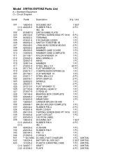
...-2 PLATE 4 PC. (XWT06) Model XWT06/XWT06Z Parts List A = Standard Equipment 〇= Circuit Diagram Item# Part# Description Q'ty Unit 001 188243-5 HOUSING SET 1 SET 001 C10 263005-3 RUBBER PIN 6 2 PC. 001 D10 INC. 38 0 002 815M87-5 XWT06 NAME PLATE 1 003 266130-9 TAPPING SCREW BIND PT 3X16 8 PC. 004 643852-2 TERMINAL 1 PC. 005 419041-9 F/R CHANGE LEVER 1 PC. 006 650652-3 SWITCH TG553FSB-1B 1 PC. 007 652045-0 +PAN HEAD SCREW M3...
...-2 PLATE 4 PC. (XWT06) Model XWT06/XWT06Z Parts List A = Standard Equipment 〇= Circuit Diagram Item# Part# Description Q'ty Unit 001 188243-5 HOUSING SET 1 SET 001 C10 263005-3 RUBBER PIN 6 2 PC. 001 D10 INC. 38 0 002 815M87-5 XWT06 NAME PLATE 1 003 266130-9 TAPPING SCREW BIND PT 3X16 8 PC. 004 643852-2 TERMINAL 1 PC. 005 419041-9 F/R CHANGE LEVER 1 PC. 006 650652-3 SWITCH TG553FSB-1B 1 PC. 007 652045-0 +PAN HEAD SCREW M3...

XWT06Z Parts Breakdown
Page 3
LABEL 2 PC. (XWT06) 1 PC. (XWT06) 1 PC. (XWT06) 1 PC. (XWT06) 1 (XWT06) A03 C30 417724-5 A03 C40 419215-2 A03 C50 419216-0 A04 450128-8 A05 803P00-3 LATCH PLASTIC CASE LID HANDLE BATTERY COVER XWT06 MODEL NO.
LABEL 2 PC. (XWT06) 1 PC. (XWT06) 1 PC. (XWT06) 1 PC. (XWT06) 1 (XWT06) A03 C30 417724-5 A03 C40 419215-2 A03 C50 419216-0 A04 450128-8 A05 803P00-3 LATCH PLASTIC CASE LID HANDLE BATTERY COVER XWT06 MODEL NO.


