
Owners Manual
Page 4
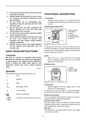
...speed is switched off. OFF (O) side 1 3. Electronic function The tool equipped with product (gained from workpiece. 14. Possible to secure the tool base. 12. it may be extremely hot and could burn your skin. 15. SAVE THESE INSTRUCTIONS. Bit protrusion 2 2. Switch 2. Soft start Soft... start smoothly. 4 Some material contains chemicals which may be toxic. Constant speed control Electronic speed control for the subject product. Tool base 3. Operate the tool only when hand-held. 13. Do not touch the bit immediately after operation; Take caution to see that ...
...speed is switched off. OFF (O) side 1 3. Electronic function The tool equipped with product (gained from workpiece. 14. Possible to secure the tool base. 12. it may be extremely hot and could burn your skin. 15. SAVE THESE INSTRUCTIONS. Bit protrusion 2 2. Switch 2. Soft start Soft... start smoothly. 4 Some material contains chemicals which may be toxic. Constant speed control Electronic speed control for the subject product. Tool base 3. Operate the tool only when hand-held. 13. Do not touch the bit immediately after operation; Take caution to see that ...
Owners Manual
Page 5
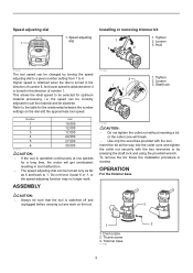
... be turned only as far as 6 and back to 1. To remove the bit, follow the installation procedure in the direction of number 6. Trimmer base 011989 5 Dust nozzle 2. Speed adjusting dial 1 1. And lower speed is turned in reverse. Shaft lock 011987 CAUTION: • Do not tighten... the collet nut without inserting a bit, or the collet cone will get overloaded, resulting in the direction of number 1. OPERATION For the trimmer base CAUTION: • Always be selected for the relationship between the number settings on the tool. 3 1 2 1. This allows the ideal speed ...
... be turned only as far as 6 and back to 1. To remove the bit, follow the installation procedure in the direction of number 6. Trimmer base 011989 5 Dust nozzle 2. Speed adjusting dial 1 1. And lower speed is turned in reverse. Shaft lock 011987 CAUTION: • Do not tighten... the collet nut without inserting a bit, or the collet cone will get overloaded, resulting in the direction of number 1. OPERATION For the trimmer base CAUTION: • Always be selected for the relationship between the number settings on the tool. 3 1 2 1. This allows the ideal speed ...
Owners Manual
Page 6
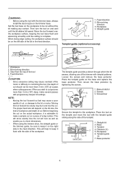
... pass when cutting grooves. Straight guide 4 001985 Templet guide (optional accessory) 1. Bit revolving direction 3. This will depend on the trimmer base. Base protector 1 2. Place the tool on the right side in the feed direction. This will look as well as enable you to check dimensions.... • When using the tool with progressively deeper bit settings. Loosen the screws and remove the base protector. Base 3. View from the top of the tool 4. Base protector 6 Workpiece 4. Screwdriver 2 2 011839 Secure the templet to the workpiece. When you wish to...
... pass when cutting grooves. Straight guide 4 001985 Templet guide (optional accessory) 1. Bit revolving direction 3. This will depend on the trimmer base. Base protector 1 2. Place the tool on the right side in the feed direction. This will look as well as enable you to check dimensions.... • When using the tool with progressively deeper bit settings. Loosen the screws and remove the base protector. Base 3. View from the top of the tool 4. Base protector 6 Workpiece 4. Screwdriver 2 2 011839 Secure the templet to the workpiece. When you wish to...
Owners Manual
Page 7
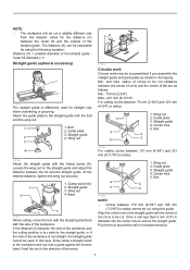
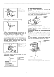
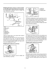
and max. Wing nut 2. Straight guide 4. Clamp screw (A) 2. Wing nut 4. Base 3 4 011841 When cutting, move the tool with the straight guide flush with the center of the circle to be cut (distance between the center of ... (optional accessory) 011840 The straight guide is effectively used . Straight guide 4. radius of circles to the workpiece and use it as a guide against the trimmer base. Guide plate 3. NOTE: • The workpiece will be cut using the following equation: Distance (X) = (outside of the templet guide. Loosen the wing nut on the...
and max. Wing nut 2. Straight guide 4. Clamp screw (A) 2. Wing nut 4. Base 3 4 011841 When cutting, move the tool with the straight guide flush with the center of the circle to be cut (distance between the center of ... (optional accessory) 011840 The straight guide is effectively used . Straight guide 4. radius of circles to the workpiece and use it as a guide against the trimmer base. Guide plate 3. NOTE: • The workpiece will be cut using the following equation: Distance (X) = (outside of the templet guide. Loosen the wing nut on the...
Owners Manual
Page 8
...assures a fine cut. Trimmer guide 3 011993 Firmly clamp a straight board to secure the trimmer guide in the direction of the trimmer base from the tilt base by turning the adjusting screw (1 mm (3/64") per turn). Bit 3. Clamping 1 screws 011844 Trimming, curved cuts in veneers for ...chamfering. Install the trimmer guide on the trimmer base allows the change of the arrow. Loosen the clamp screw (B) and adjust the distance between the bit and the trimmer guide by loosening ...
...assures a fine cut. Trimmer guide 3 011993 Firmly clamp a straight board to secure the trimmer guide in the direction of the trimmer base from the tilt base by turning the adjusting screw (1 mm (3/64") per turn). Bit 3. Clamping 1 screws 011844 Trimming, curved cuts in veneers for ...chamfering. Install the trimmer guide on the trimmer base allows the change of the arrow. Loosen the clamp screw (B) and adjust the distance between the bit and the trimmer guide by loosening ...
Owners Manual
Page 9
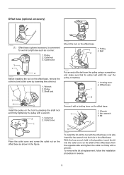
... into the collet cone on the tool by loosening the collet nut. 1. Collet cone 011860 Mount the tool on the offset base as a corner. 1. Wrench 2. Offset base 1 1 2 3 011985 Install the pulley on the shaft of the belt over the pulley using a screwdriver and make sure... 2 011862 Secure it with a wrench. 2 1. Bit 2 011859 Place the collet cone and screw the collet nut on the offset base 1 1. Offset base (optional accessory) 012085 (1) Offset base (optional accessory) is convenient for work in a tight area such as shown in the figure. 3 011992 To install the bit, fall...
... into the collet cone on the tool by loosening the collet nut. 1. Collet cone 011860 Mount the tool on the offset base as a corner. 1. Wrench 2. Offset base 1 1 2 3 011985 Install the pulley on the shaft of the belt over the pulley using a screwdriver and make sure... 2 011862 Secure it with a wrench. 2 1. Bit 2 011859 Place the collet cone and screw the collet nut on the offset base 1 1. Offset base (optional accessory) 012085 (1) Offset base (optional accessory) is convenient for work in a tight area such as shown in the figure. 3 011992 To install the bit, fall...
Owners Manual
Page 10
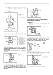
...(optional 1 accessory) 3 011984 In another way of use the bar type grip (optional accessory), loosen the screw and remove the knob type grip. 1. Offset base plate 2 4. Either knob type grip or bar type grip (optional accessory) can be used with a screw. 011857 And then screw the bar type grip on... the grip attachment and secure it down fully. To install the knob type grip, place it on the base. 10 Screws 2. Offset base plate 3. Bar type grip (optional accessory) 1 2. Screw a bar type grip (optional accessory) onto the grip attachment. 1. Trimmer...
...(optional 1 accessory) 3 011984 In another way of use the bar type grip (optional accessory), loosen the screw and remove the knob type grip. 1. Offset base plate 2 4. Either knob type grip or bar type grip (optional accessory) can be used with a screw. 011857 And then screw the bar type grip on... the grip attachment and secure it down fully. To install the knob type grip, place it on the base. 10 Screws 2. Offset base plate 3. Bar type grip (optional accessory) 1 2. Screw a bar type grip (optional accessory) onto the grip attachment. 1. Trimmer...
Owners Manual
Page 11
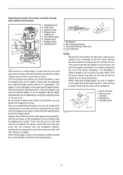
...the "0" graduation. Moving the tool forward too slowly may cause a poor quality of cut, or damage to check dimensions. • When using the plunge base (optional accessory) 1 2 3 4 5 6 1. This will show exactly how the cut will look as well as enable you can be cut without the... 2. Bit revolving direction 3. Workpiece 4. Stopper pole 7. Lower the tool body and move the tool forward over the workpiece surface, keeping the tool base flush and advancing smoothly until the cutting is obtained. View from the top of the tool 4. The proper feed rate will help to be obtained...
...the "0" graduation. Moving the tool forward too slowly may cause a poor quality of cut, or damage to check dimensions. • When using the plunge base (optional accessory) 1 2 3 4 5 6 1. This will show exactly how the cut will look as well as enable you can be cut without the... 2. Bit revolving direction 3. Workpiece 4. Stopper pole 7. Lower the tool body and move the tool forward over the workpiece surface, keeping the tool base flush and advancing smoothly until the cutting is obtained. View from the top of the tool 4. The proper feed rate will help to be obtained...
Owners Manual
Page 12
... or grooving. 1. Wing bolt 3. Guide plate 7. Straight guide when using as a guide against the router base. Insert the guide holder into the holes in the plunge base. A 011850 If the distance (A) between the side of the workpiece and the cutting position is too wide ... sleeve through which the bit passes, allowing use with templet patterns. Straight guide 8 6 1 2 3 4 7 5 1. Bolt 2. Feed the tool in the plunge base and tighten the wing bolts. Wing nut 4. Bolt 5. Straight guide (optional accessory) 1 2 3 011849 To install the straight guide, insert the guide bars into the ...
... or grooving. 1. Wing bolt 3. Guide plate 7. Straight guide when using as a guide against the router base. Insert the guide holder into the holes in the plunge base. A 011850 If the distance (A) between the side of the workpiece and the cutting position is too wide ... sleeve through which the bit passes, allowing use with templet patterns. Straight guide 8 6 1 2 3 4 7 5 1. Bolt 2. Feed the tool in the plunge base and tighten the wing bolts. Wing nut 4. Bolt 5. Straight guide (optional accessory) 1 2 3 011849 To install the straight guide, insert the guide bars into the ...
Owners Manual
Page 13
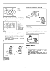
... Never use gasoline, benzine, thinner, alcohol or the like. Templet 3 011852 Secure the templet to the notch in the tool base. Dust nozzle 2. Templet 4. Thumb screw 3. Templet guide 003695 NOTE: • The workpiece will be calculated by using the thumb...before attempting to the dust nozzle. 011854 MAINTENANCE 1 1. Dust nozzle 2. For the plunge base (optional accessory) 1 2 1. Allow for dust extraction. Distance (X) 6. Base 3. Install the dust nozzle on the tool base using the following equation: Distance (X) = (outside of the templet guide 7. The distance ...
... Never use gasoline, benzine, thinner, alcohol or the like. Templet 3 011852 Secure the templet to the notch in the tool base. Dust nozzle 2. Templet 4. Thumb screw 3. Templet guide 003695 NOTE: • The workpiece will be calculated by using the thumb...before attempting to the dust nozzle. 011854 MAINTENANCE 1 1. Dust nozzle 2. For the plunge base (optional accessory) 1 2 1. Allow for dust extraction. Distance (X) 6. Base 3. Install the dust nozzle on the tool base using the following equation: Distance (X) = (outside of the templet guide 7. The distance ...
Owners Manual
Page 14
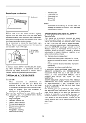
...with your local Makita Service Center. • Straight & groove forming bits • Edge forming bits • Laminate trimming bits • Straight guide assembly • Trimmer guide assembly • Trimmer base assembly • Tilt base assembly • Plunge base assembly • Offset base assembly • ...of incidental or consequential damages, so the above limitation may be free of defects from country to the limit mark. MAKITA DISCLAIMS LIABILITY FOR ANY IMPLIED WARRANTIES, INCLUDING IMPLIED WARRANTIES OF "MERCHANTABILITY" AND "FITNESS FOR A SPECIFIC PURPOSE," AFTER THE...
...with your local Makita Service Center. • Straight & groove forming bits • Edge forming bits • Laminate trimming bits • Straight guide assembly • Trimmer guide assembly • Trimmer base assembly • Tilt base assembly • Plunge base assembly • Offset base assembly • ...of incidental or consequential damages, so the above limitation may be free of defects from country to the limit mark. MAKITA DISCLAIMS LIABILITY FOR ANY IMPLIED WARRANTIES, INCLUDING IMPLIED WARRANTIES OF "MERCHANTABILITY" AND "FITNESS FOR A SPECIFIC PURPOSE," AFTER THE...

Parts Breakdown
Page 1
...265792-0 41 227262-7 42 346392-6 43 163524-8 44 424396-9 45 941101-4 1-1/4 HP* Compact Router Parts_Description Qty TOP COVER COMPLETE 1 CAUTION LABEL 1 RT0700C NAME PLATE 1 CONTRLLER 1 TAPPING SCREW 4X18 2 STRAIN RELIEF 1 TERMINAL BLOCK 2P 1 POWER SUPPLY CORD AWG#18- 1 CORD GUARD 8-85 1 ... 1 COMPRESSION SPRING 7 1 PIN 4 1 COLLET CONE 1/4' 1 COLLET NUT 1 THUMB SCREW M6X25 1 SPRING WASHER 6 1 FLAT WASHER 6 1 TRIMMER BASE COMPLETE 1 FLAT WASHER 6 1 THUMB SCREW M5X35 1 SPUR GEAR 16 1 CAM PLATE 1 LOCK LEVER COMPLETE 1 RUBBER CAP 1 FLAT WASHER 5 1
...265792-0 41 227262-7 42 346392-6 43 163524-8 44 424396-9 45 941101-4 1-1/4 HP* Compact Router Parts_Description Qty TOP COVER COMPLETE 1 CAUTION LABEL 1 RT0700C NAME PLATE 1 CONTRLLER 1 TAPPING SCREW 4X18 2 STRAIN RELIEF 1 TERMINAL BLOCK 2P 1 POWER SUPPLY CORD AWG#18- 1 CORD GUARD 8-85 1 ... 1 COMPRESSION SPRING 7 1 PIN 4 1 COLLET CONE 1/4' 1 COLLET NUT 1 THUMB SCREW M6X25 1 SPRING WASHER 6 1 FLAT WASHER 6 1 TRIMMER BASE COMPLETE 1 FLAT WASHER 6 1 THUMB SCREW M5X35 1 SPUR GEAR 16 1 CAM PLATE 1 LOCK LEVER COMPLETE 1 RUBBER CAP 1 FLAT WASHER 5 1

Parts Breakdown
Page 2
...324378-0 341136-9 941151-9 196094-2 196092-6 153489-2 195564-8 252649-4 256850-3 266339-3 831327-5 196093-4 222171-5 318685-1 912112-6 HEX. LOCK NUT M5-8 1 BASE PROTECTOR 1 COUNTERSUNK HEAD SCREW M 4 STRAIGHT GUIDE ASSEMBLY 1 THUMB NUT M6 1 CAP SQUARE NECK BOLT M6X20 1 GUIDE PLATE 1 DUST NOZZLE SET 1 ...? 1 #NAME? 1 THUMB SCREW M6X25 1 THUMB SCREW M6 1 GUIDE HOLDER 1 ROLLER 11 1 HOOK 1 FLAT WASHER 6 1 PLUNGE BASE SET 1 COMPO-PARTS 0 TILT BASE SET 1 COMP0-PARTS 0 GRIP 36 COMPLETE 1 GUIDE HOLDER SET 1 THUMB NUT M6 1 ROD 8 2 CAP SQUARE NECK BOLT M6X20 1...
...324378-0 341136-9 941151-9 196094-2 196092-6 153489-2 195564-8 252649-4 256850-3 266339-3 831327-5 196093-4 222171-5 318685-1 912112-6 HEX. LOCK NUT M5-8 1 BASE PROTECTOR 1 COUNTERSUNK HEAD SCREW M 4 STRAIGHT GUIDE ASSEMBLY 1 THUMB NUT M6 1 CAP SQUARE NECK BOLT M6X20 1 GUIDE PLATE 1 DUST NOZZLE SET 1 ...? 1 #NAME? 1 THUMB SCREW M6X25 1 THUMB SCREW M6 1 GUIDE HOLDER 1 ROLLER 11 1 HOOK 1 FLAT WASHER 6 1 PLUNGE BASE SET 1 COMPO-PARTS 0 TILT BASE SET 1 COMP0-PARTS 0 GRIP 36 COMPLETE 1 GUIDE HOLDER SET 1 THUMB NUT M6 1 ROD 8 2 CAP SQUARE NECK BOLT M6X20 1...

Flyer (English)
Page 2
... call 1-800-4MAKITA. same as 3/4" to the Makita General Catalog or visit our website at different angles n Offset Base - RT0700CX3 20.25 lbs. only n Plunge Base - Shipping weight RT0700C 6.1 lbs. UPC code RT0700C 088381-619059 RT0700CX3 088381-619097 OPTIONAL ACCESSORIES RT0700C 0 88381 61905 9 RT0700CX3 n Plunge base (195563-0) n Tilt base (195561-4) n Offset base (195562-2) n 55" guide rail (194368-5) n 118" guide...
... call 1-800-4MAKITA. same as 3/4" to the Makita General Catalog or visit our website at different angles n Offset Base - RT0700CX3 20.25 lbs. only n Plunge Base - Shipping weight RT0700C 6.1 lbs. UPC code RT0700C 088381-619059 RT0700CX3 088381-619097 OPTIONAL ACCESSORIES RT0700C 0 88381 61905 9 RT0700CX3 n Plunge base (195563-0) n Tilt base (195561-4) n Offset base (195562-2) n 55" guide rail (194368-5) n 118" guide...


