
Owners Manual
Page 3
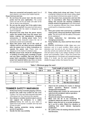
... from rotating parts. 9. Check the bit carefully for cord Ampere Rating More Than 0 6 10 12 000173 Not More Than 6 10 12 16 Volts 120 V GEB019-4 TRIMMER SAFETY WARNINGS 1. Before using an extension cord, be controlled with sharp cutting edges are less likely to carry the current your application.
... from rotating parts. 9. Check the bit carefully for cord Ampere Rating More Than 0 6 10 12 000173 Not More Than 6 10 12 16 Volts 120 V GEB019-4 TRIMMER SAFETY WARNINGS 1. Before using an extension cord, be controlled with sharp cutting edges are less likely to carry the current your application.
Owners Manual
Page 5
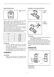
... 1. Loosen 3. Hold 3 2 011835 The tool speed can be correctly adjusted to 6. ASSEMBLY 011837 1 3 2 1. OPERATION For the trimmer base CAUTION: • Always be turned only as far as 6 and back to the table for the relationship between the number settings on the ...get overloaded, resulting in the direction of number 1. To remove the bit, follow the installation procedure in the direction of number 6. Thumb screw 3. Trimmer base 011989 5 Insert the bit all the way into the collet cone and tighten the collet nut securely with the tool. Tighten 1 2. Tighten 2....
... 1. Loosen 3. Hold 3 2 011835 The tool speed can be correctly adjusted to 6. ASSEMBLY 011837 1 3 2 1. OPERATION For the trimmer base CAUTION: • Always be turned only as far as 6 and back to the table for the relationship between the number settings on the ...get overloaded, resulting in the direction of number 1. To remove the bit, follow the installation procedure in the direction of number 6. Thumb screw 3. Trimmer base 011989 5 Insert the bit all the way into the collet cone and tighten the collet nut securely with the tool. Tighten 1 2. Tighten 2....
Owners Manual
Page 6
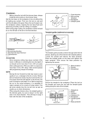
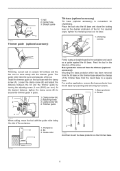
... enable you wish to cut should be on and wait until the cutting is advisable to make several passes with the trimmer base, always install the dust nozzle on the trimmer base. Then secure the base protector by tightening the screws. 1. Base protector 1 2. Screws 3 3. Screwdriver 2 2 011839...3. Templet guide 10 7. Distance (X) 5. View from the top of the tool 4. Base 3. WARNING: • Before using the trimmer shoe, the straight guide or the trimmer guide, be sure to keep it flush with the side of the workpiece. 011838 The templet guide provides a sleeve through which the...
... enable you wish to cut should be on and wait until the cutting is advisable to make several passes with the trimmer base, always install the dust nozzle on the trimmer base. Then secure the base protector by tightening the screws. 1. Base protector 1 2. Screws 3 3. Screwdriver 2 2 011839...3. Templet guide 10 7. Distance (X) 5. View from the top of the tool 4. Base 3. WARNING: • Before using the trimmer shoe, the straight guide or the trimmer guide, be sure to keep it flush with the side of the workpiece. 011838 The templet guide provides a sleeve through which the...
Owners Manual
Page 7
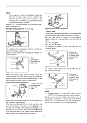
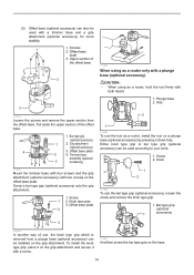
.... Straight guide 3. Wing nut 3 4 A 011842 Circular work Circular work may be accomplished if you assemble the straight guide and guide plate as a guide against the trimmer base. Base 3 4 011841 When cutting, move the tool with the straight guide flush with the center of the workpiece. Center hole 5. Wing nut 1 2. Align the...
.... Straight guide 3. Wing nut 3 4 A 011842 Circular work Circular work may be accomplished if you assemble the straight guide and guide plate as a guide against the trimmer base. Base 3 4 011841 When cutting, move the tool with the straight guide flush with the center of the workpiece. Center hole 5. Wing nut 1 2. Align the...
Owners Manual
Page 8
...roller 3 1 2 011994 And then mount the base protector on its sides. 1. For desired angle, tighten the clamping screws on the trimmer base. 001998 8 Install the trimmer guide on the trimmer base allows the change of the bit. Adjusting screw 2 3. Feed the tool in veneers for chamfering. The guide roller rides the ...curve and assures a fine cut. 1. Center hole 3. Loosen the clamp screw (B) and adjust the distance between the bit and the trimmer guide by loosening and removing four screws. 1. At the desired distance, tighten the clamp screw (B) to secure the...
...roller 3 1 2 011994 And then mount the base protector on its sides. 1. For desired angle, tighten the clamping screws on the trimmer base. 001998 8 Install the trimmer guide on the trimmer base allows the change of the bit. Adjusting screw 2 3. Feed the tool in veneers for chamfering. The guide roller rides the ...curve and assures a fine cut. 1. Center hole 3. Loosen the clamp screw (B) and adjust the distance between the bit and the trimmer guide by loosening and removing four screws. 1. At the desired distance, tighten the clamp screw (B) to secure the...
Owners Manual
Page 10
... knob type grip. 1. Screws 2. Plunge base 2. Knob 1 2 011856 To use , the knob type grip which is removed from the offset base. Trimmer base assembly (optional 3 accessory) 011935 Mount the trimmer base with four screws and the grip attachment (optional accessory) with both hands. 1. Knob type grip 3. (2) Offset base (optional accessory) can also... be used with a screw. 011857 And then screw the bar type grip on the base. 10 To install the knob type grip, place it with a trimmer base and a grip attachment (optional accessory) for more stability. 1 1.
... knob type grip. 1. Screws 2. Plunge base 2. Knob 1 2 011856 To use , the knob type grip which is removed from the offset base. Trimmer base assembly (optional 3 accessory) 011935 Mount the trimmer base with four screws and the grip attachment (optional accessory) with both hands. 1. Knob type grip 3. (2) Offset base (optional accessory) can also... be used with a screw. 011857 And then screw the bar type grip on the base. 10 To install the knob type grip, place it with a trimmer base and a grip attachment (optional accessory) for more stability. 1 1.
Owners Manual
Page 13
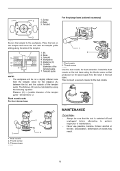
... nozzle 2. Base 3. Screw 2. Place the tool on the templet and move the tool with the templet guide sliding along the side of the templet guide 7. Trimmer base 011989 3 2 CAUTION: • Always be sure that protrusion on the tool base using the following equation: Distance (X) = (outside of the templet guide - For the... cracks may result. 13 Bit 2. Dust nozzle 2. The distance (X) can be cut a slightly different size from the templet. bit diameter) / 2 Dust nozzle sets For the trimmer base 1 2 1.
... nozzle 2. Base 3. Screw 2. Place the tool on the templet and move the tool with the templet guide sliding along the side of the templet guide 7. Trimmer base 011989 3 2 CAUTION: • Always be sure that protrusion on the tool base using the following equation: Distance (X) = (outside of the templet guide - For the... cracks may result. 13 Bit 2. Dust nozzle 2. The distance (X) can be cut a slightly different size from the templet. bit diameter) / 2 Dust nozzle sets For the trimmer base 1 2 1.
Owners Manual
Page 14
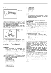
...from workmanship and materials for use with your local Makita Service Center. • Straight & groove forming bits • Edge forming bits • Laminate trimming bits • Straight guide assembly • Trimmer guide assembly • Trimmer base assembly • Tilt base assembly •... accessories. Brush holder cap 1 2 011846 To maintain product SAFETY and RELIABILITY, repairs, any assistance for its stated purpose. MAKITA DISCLAIMS LIABILITY FOR ANY IMPLIED WARRANTIES, INCLUDING IMPLIED WARRANTIES OF "MERCHANTABILITY" AND "FITNESS FOR A SPECIFIC PURPOSE," AFTER THE ONE...
...from workmanship and materials for use with your local Makita Service Center. • Straight & groove forming bits • Edge forming bits • Laminate trimming bits • Straight guide assembly • Trimmer guide assembly • Trimmer base assembly • Tilt base assembly •... accessories. Brush holder cap 1 2 011846 To maintain product SAFETY and RELIABILITY, repairs, any assistance for its stated purpose. MAKITA DISCLAIMS LIABILITY FOR ANY IMPLIED WARRANTIES, INCLUDING IMPLIED WARRANTIES OF "MERCHANTABILITY" AND "FITNESS FOR A SPECIFIC PURPOSE," AFTER THE ONE...

Parts Breakdown
Page 1
...-0 41 227262-7 42 346392-6 43 163524-8 44 424396-9 45 941101-4 1-1/4 HP* Compact Router Parts_Description Qty TOP COVER COMPLETE 1 CAUTION LABEL 1 RT0700C NAME PLATE 1 CONTRLLER 1 TAPPING SCREW 4X18 2 STRAIN RELIEF 1 TERMINAL BLOCK 2P 1 POWER SUPPLY CORD AWG#18- 1 CORD GUARD 8-85 1... BUTTON 1 COMPRESSION SPRING 7 1 PIN 4 1 COLLET CONE 1/4' 1 COLLET NUT 1 THUMB SCREW M6X25 1 SPRING WASHER 6 1 FLAT WASHER 6 1 TRIMMER BASE COMPLETE 1 FLAT WASHER 6 1 THUMB SCREW M5X35 1 SPUR GEAR 16 1 CAM PLATE 1 LOCK LEVER COMPLETE 1 RUBBER CAP 1 FLAT WASHER 5 1
...-0 41 227262-7 42 346392-6 43 163524-8 44 424396-9 45 941101-4 1-1/4 HP* Compact Router Parts_Description Qty TOP COVER COMPLETE 1 CAUTION LABEL 1 RT0700C NAME PLATE 1 CONTRLLER 1 TAPPING SCREW 4X18 2 STRAIN RELIEF 1 TERMINAL BLOCK 2P 1 POWER SUPPLY CORD AWG#18- 1 CORD GUARD 8-85 1... BUTTON 1 COMPRESSION SPRING 7 1 PIN 4 1 COLLET CONE 1/4' 1 COLLET NUT 1 THUMB SCREW M6X25 1 SPRING WASHER 6 1 FLAT WASHER 6 1 TRIMMER BASE COMPLETE 1 FLAT WASHER 6 1 THUMB SCREW M5X35 1 SPUR GEAR 16 1 CAM PLATE 1 LOCK LEVER COMPLETE 1 RUBBER CAP 1 FLAT WASHER 5 1

Parts Breakdown
Page 2
... SET 1 TEMPLET GUIDE 10 1 THUMB SCREW M4X19 1 TEMPLET GUIDE 10 1 COLLET CONE 3/8' 1 COLLET CONE 3/8' 1 WRENCH 22 1 WRENCH 13 1 WRENCH 22 1 WRENCH 13 1 TEMPLET GUIDE 16 1 TRIMMER GUIDE ASS'Y 1 #NAME? 1 #NAME? 1 THUMB SCREW M6X25 1 THUMB SCREW M6 1 GUIDE HOLDER 1 ROLLER 11 1 HOOK 1 FLAT WASHER 6 1 PLUNGE BASE SET 1 COMPO-PARTS 0 TILT BASE SET...
... SET 1 TEMPLET GUIDE 10 1 THUMB SCREW M4X19 1 TEMPLET GUIDE 10 1 COLLET CONE 3/8' 1 COLLET CONE 3/8' 1 WRENCH 22 1 WRENCH 13 1 WRENCH 22 1 WRENCH 13 1 TEMPLET GUIDE 16 1 TRIMMER GUIDE ASS'Y 1 #NAME? 1 #NAME? 1 THUMB SCREW M6X25 1 THUMB SCREW M6 1 GUIDE HOLDER 1 ROLLER 11 1 HOOK 1 FLAT WASHER 6 1 PLUNGE BASE SET 1 COMPO-PARTS 0 TILT BASE SET...

Flyer (English)
Page 2
...stock on hand. with 0"-1-3/8" depth capacity for routing as close as RT0700C plus: n Plunge base (195563-0) n Template guide 16mm (344364-5) n Tilt base (195561-4) n Side handle (153489-2) n Offset base (195562-2) n Trimmer guide (122703-7) n Dust nozzle (194733-8) n Tool bag (831327-5)... n Guide rail clamp set (194385-5) Makita offers a wide variety of Makita Corporation." provides routing at makitatools.com, or call 1-800-4MAKITA. RT0700CX3 20.25 lbs. Shipping weight RT0700C 6.1 lbs. All specifications subject to the Makita General Catalog or visit our website at ...
...stock on hand. with 0"-1-3/8" depth capacity for routing as close as RT0700C plus: n Plunge base (195563-0) n Template guide 16mm (344364-5) n Tilt base (195561-4) n Side handle (153489-2) n Offset base (195562-2) n Trimmer guide (122703-7) n Dust nozzle (194733-8) n Tool bag (831327-5)... n Guide rail clamp set (194385-5) Makita offers a wide variety of Makita Corporation." provides routing at makitatools.com, or call 1-800-4MAKITA. RT0700CX3 20.25 lbs. Shipping weight RT0700C 6.1 lbs. All specifications subject to the Makita General Catalog or visit our website at ...


