
Owners Manual
Page 3
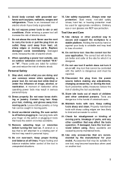
... risk of starting . Stay alert, watch what you are recommended by the manufacturer for your body is left attached to loss of parts, and any adjustments, changing accessories, or storing the tool. Keep your application. Do not overreach. Tool Use and Care 15. Such ... stable platform. Do not use an outdoor extension cord marked "W-A" or "W". Dress properly. Remove adjusting keys or wrenches before plugging in moving parts, breakage of control. 16. Always wear eye protection. Dust mask, non-skid safety shoes, hard hat, or hearing protection must be suitable ...
... risk of starting . Stay alert, watch what you are recommended by the manufacturer for your body is left attached to loss of parts, and any adjustments, changing accessories, or storing the tool. Keep your application. Do not overreach. Tool Use and Care 15. Such ... stable platform. Do not use an outdoor extension cord marked "W-A" or "W". Dress properly. Remove adjusting keys or wrenches before plugging in moving parts, breakage of control. 16. Always wear eye protection. Dust mask, non-skid safety shoes, hard hat, or hearing protection must be suitable ...

Owners Manual
Page 4
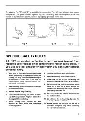
... performed only by unqualified personnel could result in feet 25 ft. 50 ft. 100 ft. 150 ft. Table 1: Minimum gage for use only identical replacement parts. The green (or green and yellow) conductor in good condition. Your unit is for cord Ampere Rating More Than 0 6 10 12 Not More Than ...6 10 12 16 Volts 120 V Total length of cord in a risk of unauthorized parts or failure to a live terminal. Use of injury. 24. Never connect the green (or green and yellow) wire to follow Maintenance instructions may create a ...
... performed only by unqualified personnel could result in feet 25 ft. 50 ft. 100 ft. 150 ft. Table 1: Minimum gage for use only identical replacement parts. The green (or green and yellow) conductor in good condition. Your unit is for cord Ampere Rating More Than 0 6 10 12 Not More Than ...6 10 12 16 Volts 120 V Total length of cord in a risk of unauthorized parts or failure to a live terminal. Use of injury. 24. Never connect the green (or green and yellow) wire to follow Maintenance instructions may create a ...
Owners Manual
Page 5
C SPECIFIC SAFETY RULES USB013-3 DO NOT let comfort or familiarity with a "live" wire will make exposed metal parts of the bit rotating direction and the feed direction. 11. If you can suffer serious personal injury. 1. Inspect for vibration or wobbling that ... using the tool on . 9. Keep hands away from the adapter must be connected to two- The green-colored rigid ear, lug, etc., extending from rotating parts. 8. B Grounding Means Fig. Hold the tool firmly with both hands. 7. prong receptacles. Operate the tool only when hand-held. 12. "A" type plugs to a ...
C SPECIFIC SAFETY RULES USB013-3 DO NOT let comfort or familiarity with a "live" wire will make exposed metal parts of the bit rotating direction and the feed direction. 11. If you can suffer serious personal injury. 1. Inspect for vibration or wobbling that ... using the tool on . 9. Keep hands away from the adapter must be connected to two- The green-colored rigid ear, lug, etc., extending from rotating parts. 8. B Grounding Means Fig. Hold the tool firmly with both hands. 7. prong receptacles. Operate the tool only when hand-held. 12. "A" type plugs to a ...
Owners Manual
Page 12
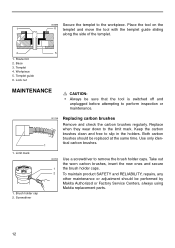
... to remove the brush holder caps. Use only identical carbon brushes. 1 1. Workpiece 5. Lock nut MAINTENANCE CAUTION: • Always be performed by Makita Authorized or Factory Service Centers, always using Makita replacement parts. 12 Take out the worn carbon brushes, insert the new ones and secure 1 the brush holder caps. 2 To maintain product SAFETY...
... to remove the brush holder caps. Use only identical carbon brushes. 1 1. Workpiece 5. Lock nut MAINTENANCE CAUTION: • Always be performed by Makita Authorized or Factory Service Centers, always using Makita replacement parts. 12 Take out the worn carbon brushes, insert the new ones and secure 1 the brush holder caps. 2 To maintain product SAFETY...
Parts Breakdown
Page 2
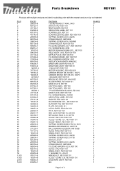
...N/A Quantity 3 1 1 1 1 1 2 1 1 1 1 1 1 1 1 2 1 1 1 1 1 1 1 1 2 2 2 1 1 1 3 1 1 1 1 1 1 1 1 1 1 1 1 1 1 2 1 1 1 1 4 4 1 2 1 1 1 1 1 2 1 1 1 Page 2 of 2 8/18/2010 Parts Breakdown RD1101 Products with multiple versions are listed in subsiding order with the newest version on top not indented Fig # 1 2 3 4 5 6 7 8 9 10 11 13 14 15 16 17...-9 655116-2 183218-9 253853-8 781031-5 193214-9 534044-3 810253-1 Part Name T.SCREW BIND CT 4X40, 9403 SWITCH, RD1100/1101 REAR COVER, RD1101 INDICATION LABEL, RP1101 CONTROLLER, RD1101 CONTROLLER HOLDER, RD1100/1101 TAPPING SCREW 4X18, 4323K STRAIN RELIEF,...
...N/A Quantity 3 1 1 1 1 1 2 1 1 1 1 1 1 1 1 2 1 1 1 1 1 1 1 1 2 2 2 1 1 1 3 1 1 1 1 1 1 1 1 1 1 1 1 1 1 2 1 1 1 1 4 4 1 2 1 1 1 1 1 2 1 1 1 Page 2 of 2 8/18/2010 Parts Breakdown RD1101 Products with multiple versions are listed in subsiding order with the newest version on top not indented Fig # 1 2 3 4 5 6 7 8 9 10 11 13 14 15 16 17...-9 655116-2 183218-9 253853-8 781031-5 193214-9 534044-3 810253-1 Part Name T.SCREW BIND CT 4X40, 9403 SWITCH, RD1100/1101 REAR COVER, RD1101 INDICATION LABEL, RP1101 CONTROLLER, RD1101 CONTROLLER HOLDER, RD1100/1101 TAPPING SCREW 4X18, 4323K STRAIN RELIEF,...


