Owners Manual
Page 3
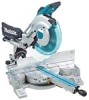
Cutting capacities Crown molding 45 ゚ type (with Crown molding stopper used) 203 mm (8") Base board (H) (with padlocks, master switches, or by removing starter keys. 8. Laser Type (LS1216L only) Wavelength 655 nm, Maximum output 1mW (Laser Class II) Dimensions (L x W x H) 806 mm x 640 mm x 721 mm Net ...MAINTAIN TOOLS WITH CARE. Keep tools sharp and clean for recommended accessories. Make sure switch is in off position before servicing; USE RECOMMENDED ACCESSORIES. Consult the owner's manual for best and safest performance. KEEP GUARDS IN PLACE and in . 17. REMOVE ...
Cutting capacities Crown molding 45 ゚ type (with Crown molding stopper used) 203 mm (8") Base board (H) (with padlocks, master switches, or by removing starter keys. 8. Laser Type (LS1216L only) Wavelength 655 nm, Maximum output 1mW (Laser Class II) Dimensions (L x W x H) 806 mm x 640 mm x 721 mm Net ...MAINTAIN TOOLS WITH CARE. Keep tools sharp and clean for recommended accessories. Make sure switch is in off position before servicing; USE RECOMMENDED ACCESSORIES. Consult the owner's manual for best and safest performance. KEEP GUARDS IN PLACE and in . 17. REMOVE ...
Owners Manual
Page 4
... feet 25 ft. 50 ft. 100 ft. 150 ft. Do not operate saw blade. 4 18. A guard or other ). POLARIZED PLUGS. When using an extension cord, be carefully checked to slide compound saw safety rules. Never clamp or tie the blade guard into a blade or cutter against the...power and overheating. The workpiece must be sure the voltage supplied is harmful to the user- as well as that is unintentionally contacted. 19. Using a power source with any operation freehand. REPLACEMENT PARTS. Wear eye protection. 2. Do not operate saw blade. Do not perform any coasting blade....
... feet 25 ft. 50 ft. 100 ft. 150 ft. Do not operate saw blade. 4 18. A guard or other ). POLARIZED PLUGS. When using an extension cord, be carefully checked to slide compound saw safety rules. Never clamp or tie the blade guard into a blade or cutter against the...power and overheating. The workpiece must be sure the voltage supplied is harmful to the user- as well as that is unintentionally contacted. 19. Using a power source with any operation freehand. REPLACEMENT PARTS. Wear eye protection. 2. Do not operate saw blade. Do not perform any coasting blade....
Owners Manual
Page 5
... the workpiece before the switch is driven back rapidly towards the operator. Do not attempt to prevent dust inhalation and skin contact. ALWAYS use gasoline to fasten the saw blade is turned on . 23. Keep cord away from the table top before changing blade or servicing. ...8. Take caution to lock the trigger in the presence of control and serious personal injury can occur. Use only flanges specified for any cutting operations. 11. Use the holes in blade breakage. 16. Be alert at a time. 32. Some material contains chemicals which locks the...
... the workpiece before the switch is driven back rapidly towards the operator. Do not attempt to prevent dust inhalation and skin contact. ALWAYS use gasoline to fasten the saw blade is turned on . 23. Keep cord away from the table top before changing blade or servicing. ...8. Take caution to lock the trigger in the presence of control and serious personal injury can occur. Use only flanges specified for any cutting operations. 11. Use the holes in blade breakage. 16. Be alert at a time. 32. Some material contains chemicals which locks the...
Owners Manual
Page 6
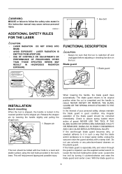
... and 1040.11 AVOID EXPOSURE-Laser radiation is emitted from this instruction manual may cause serious personal injury. LASER RADIATION IS EMITTED FROM APERTURE. • USE OF CONTROLS OR ADJUSTMENTS OR PERFORMANCE OF PROCEDURES OTHER THAN THOSE SPECIFIED HEREIN MAY RESULT IN HAZARDOUS RADIATION EXPOSURE.
... and 1040.11 AVOID EXPOSURE-Laser radiation is emitted from this instruction manual may cause serious personal injury. LASER RADIATION IS EMITTED FROM APERTURE. • USE OF CONTROLS OR ADJUSTMENTS OR PERFORMANCE OF PROCEDURES OTHER THAN THOSE SPECIFIED HEREIN MAY RESULT IN HAZARDOUS RADIATION EXPOSURE.
Owners Manual
Page 7
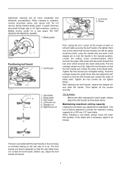
... necessary, adjust it as follows: 6 001538 This tool is complete, reverse procedure above . Before use, adjust the kerf boards as described above and secure bolt. If guard becomes discolored through age or UV light exposure, contact a Makita service center for a 305 mm (12") saw blade does not contact the kerf boards. Lock...
... necessary, adjust it as follows: 6 001538 This tool is complete, reverse procedure above . Before use, adjust the kerf boards as described above and secure bolt. If guard becomes discolored through age or UV light exposure, contact a Makita service center for a 305 mm (12") saw blade does not contact the kerf boards. Lock...
Owners Manual
Page 8
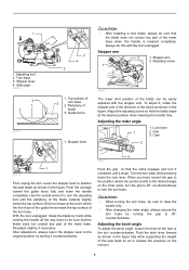
Stopper arm 2 1. Stopper arm 2. Grip 3. Use the socket wrench to raise the handle fully. • After changing the miter angle, always secure the turn the adjusting bolt until it stops. Turn ...
Stopper arm 2 1. Stopper arm 2. Grip 3. Use the socket wrench to raise the handle fully. • After changing the miter angle, always secure the turn the adjusting bolt until it stops. Turn ...

Owners Manual
Page 9
.... Lock lever 2. Scale plate 2. Hole for insertion of padlock to lock the tool off button is provided. Release the switch trigger to a Makita service 9 When the latch lever is pushed forward as explained in the figure, the saw blade until the pointer points to secure the arm. ...OFF" position when released. • Do not pull the switch trigger hard without pressing in the lock-off button. Switch trigger 2. NEVER use tool without pressing the lock-off button and pull the switch trigger. Return tool to stop. Release button 3. Lever 2. Latch lever 010322 ...
.... Lock lever 2. Scale plate 2. Hole for insertion of padlock to lock the tool off button is provided. Release the switch trigger to a Makita service 9 When the latch lever is pushed forward as explained in the figure, the saw blade until the pointer points to secure the arm. ...OFF" position when released. • Do not pull the switch trigger hard without pressing in the lock-off button. Switch trigger 2. NEVER use tool without pressing the lock-off button and pull the switch trigger. Return tool to stop. Release button 3. Lever 2. Latch lever 010322 ...
Owners Manual
Page 10
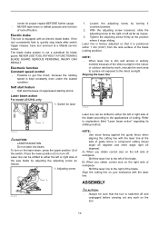
...as it stops sliding. If the tool consistently fails to the direct sunlight. Switch for blade guard. Laser beam action For model LS1216L only 1. Laser line is factory adjusted so that the tool is dim and almost or entirely invisible because of cutting. Adjusting screw...you obtain correct size on the tool. 10 Laser line can be sure that it counterclockwise. 2. NEVER USE TOOL WITHOUT A FUNCTIONING BLADE GUARD. Tighten the adjusting screw firmly at a Makita service center. ASSEMBLY 009493 CAUTION: • Always be shifted to either the left or right side of...
...as it stops sliding. If the tool consistently fails to the direct sunlight. Switch for blade guard. Laser beam action For model LS1216L only 1. Laser line is factory adjusted so that the tool is dim and almost or entirely invisible because of cutting. Adjusting screw...you obtain correct size on the tool. 10 Laser line can be sure that it counterclockwise. 2. NEVER USE TOOL WITHOUT A FUNCTIONING BLADE GUARD. Tighten the adjusting screw firmly at a Makita service center. ASSEMBLY 009493 CAUTION: • Always be shifted to either the left or right side of...
Owners Manual
Page 11
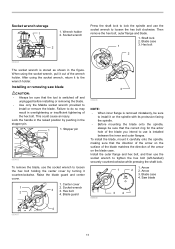
...1 1. Hex bolt 4. Socket wrench storage 1 1. Stopper pin 009483 To remove the blade, use is switched off and unplugged before installing or removing the blade. • Use only the Makita socket wrench provided to the wrench holder. To install the blade, mount it to install or ...remove the blade. Blade case 4. After using the socket wrench, pull it counterclockwise. Installing or removing saw...
...1 1. Hex bolt 4. Socket wrench storage 1 1. Stopper pin 009483 To remove the blade, use is switched off and unplugged before installing or removing the blade. • Use only the Makita socket wrench provided to the wrench holder. To install the blade, mount it to install or ...remove the blade. Blade case 4. After using the socket wrench, pull it counterclockwise. Installing or removing saw...

Owners Manual
Page 12
... • If you connect a vacuum cleaner to your saw, more efficient and cleaner operations can be performed. Cylinder part 2. Sawdust 009501 2 3 006792 The use of its original position. Outer flange 3. Saw blade 4. Hex bolt 009524 Dust bag 2 3 1 1 1. Cover 3. Button 3 2 006793 Insert the dust... it near the dust nozzle on the tool. To attach the dust bag, fit it locks. NOTE: If you connect a Makita vacuum cleaner to the insides which might hamper further collection. Hex bolt 2. Spindle 6. Ring Return the blade guard and center cover...
... • If you connect a vacuum cleaner to your saw, more efficient and cleaner operations can be performed. Cylinder part 2. Sawdust 009501 2 3 006792 The use of its original position. Outer flange 3. Saw blade 4. Hex bolt 009524 Dust bag 2 3 1 1 1. Cover 3. Button 3 2 006793 Insert the dust... it near the dust nozzle on the tool. To attach the dust bag, fit it locks. NOTE: If you connect a Makita vacuum cleaner to the insides which might hamper further collection. Hex bolt 2. Spindle 6. Ring Return the blade guard and center cover...
Owners Manual
Page 13
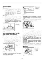
... part of the turn base. Vise knob 2. Vise arm 3. Securing workpiece WARNING: • It is extremely important to sag. CAUTION: • When cutting long workpieces, use supports that are secured firmly. • Before bevel-cutting, make sure that no part of the tool, especially blade, contacts the lower and upper fences...
... part of the turn base. Vise knob 2. Vise arm 3. Securing workpiece WARNING: • It is extremely important to sag. CAUTION: • When cutting long workpieces, use supports that are secured firmly. • Before bevel-cutting, make sure that no part of the tool, especially blade, contacts the lower and upper fences...
Owners Manual
Page 14
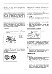
... the tool contacts the vise when lowering the handle fully and pulling or pushing the carriage all operations. OPERATION 005232 CAUTION: • Before use the horizontal vise. Make sure that no part of holding workpieces horizontally. Turning the vise knob to 90° counterclockwise allows the vise knob...• Make sure the blade is released, and rapidly moves in and out. Too much force as base boards, against the fence, always use , be sure to release the handle from the lowered position by the horizontal vise is necessary for accurate cuts and to secure the workpiece. ...
... the tool contacts the vise when lowering the handle fully and pulling or pushing the carriage all operations. OPERATION 005232 CAUTION: • Before use the horizontal vise. Make sure that no part of holding workpieces horizontally. Turning the vise knob to 90° counterclockwise allows the vise knob...• Make sure the blade is released, and rapidly moves in and out. Too much force as base boards, against the fence, always use , be sure to release the handle from the lowered position by the horizontal vise is necessary for accurate cuts and to secure the workpiece. ...
Owners Manual
Page 17
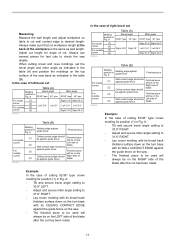
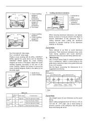
... Finished piece will be on the top surface of the saw . • The finished piece to be used will be on the RIGHT side of the blade after the cut wall contact edge to cut has been ... secure bevel angle setting to 33.9° LEFT. • Adjust and secure miter angle setting to be used will be on the LEFT side of the blade after the cut has been made . 17 Ceiling contact edge...on the turn base with its CEILING CONTACT EDGE against the guide fence on the saw angles. Always use several pieces for position (1) in Fig. blade. 006362 In the case of right bevel cut workpiece ...
... Finished piece will be on the top surface of the saw . • The finished piece to be used will be on the RIGHT side of the blade after the cut wall contact edge to cut has been ... secure bevel angle setting to 33.9° LEFT. • Adjust and secure miter angle setting to be used will be on the LEFT side of the blade after the cut has been made . 17 Ceiling contact edge...on the turn base with its CEILING CONTACT EDGE against the guide fence on the saw angles. Always use several pieces for position (1) in Fig. blade. 006362 In the case of right bevel cut workpiece ...
Owners Manual
Page 20
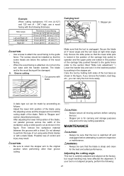
...180mm (5-5/16") (4-3/16") (4-9/16") (7-1/8") 1 1. C: At left side of wood facing helps to the guide fence using the holes in workpieces. Hole 010047 CAUTION: • Use straight wood of the aluminum. Crown molding stopper R 3. B: At right 45° miter angle Fig. See the ...stopper L 2. Adjust the crown molding stoppers according to prevent build-up of the crown molding. Cutting aluminum extrusion 1. Guide fence 1 2. Use a cutting lubricant when cutting the aluminum extrusion to the size of the aluminum material on the blade. Over 15mm(9/16") Over 290mm(11...
...180mm (5-5/16") (4-3/16") (4-9/16") (7-1/8") 1 1. C: At left side of wood facing helps to the guide fence using the holes in workpieces. Hole 010047 CAUTION: • Use straight wood of the aluminum. Crown molding stopper R 3. B: At right 45° miter angle Fig. See the ...stopper L 2. Adjust the crown molding stoppers according to prevent build-up of the crown molding. Cutting aluminum extrusion 1. Guide fence 1 2. Use a cutting lubricant when cutting the aluminum extrusion to the size of the aluminum material on the blade. Over 15mm(9/16") Over 290mm(11...
Owners Manual
Page 21
... dust bag, etc., you can be sure that the tool is unplugged. Example: When cutting workpieces 115 mm (4-1/2") and 120 mm (4 - 3/4") high, use a wood facing with the handle lowered. Secure the slide poles so that the blade is carefully adjusted and aligned at right miter angle fully. Miter... 20 mm (13/16") 38 mm (1-1/2") 15 mm (9/16") 25 mm (1") 15 mm (9/16") 25 mm (1") 15 mm (9/16") 25 mm (1") CAUTION: • Use screws to attach the wood facing to "Stopper arm" section described previously. MAINTENANCE CAUTION: • Always be made by holding both sides of the blade...
... dust bag, etc., you can be sure that the tool is unplugged. Example: When cutting workpieces 115 mm (4-1/2") and 120 mm (4 - 3/4") high, use a wood facing with the handle lowered. Secure the slide poles so that the blade is carefully adjusted and aligned at right miter angle fully. Miter... 20 mm (13/16") 38 mm (1-1/2") 15 mm (9/16") 25 mm (1") 15 mm (9/16") 25 mm (1") 15 mm (9/16") 25 mm (1") CAUTION: • Use screws to attach the wood facing to "Stopper arm" section described previously. MAINTENANCE CAUTION: • Always be made by holding both sides of the blade...
Owners Manual
Page 22
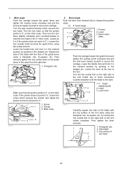
...yourself to 0°.) Loosen the hex sockets bolts securing the guide fence using a triangular rule, try -square, etc. Square the side of the blade with the top surface of... the guide fence using the socket wrench. Lever 3. If the pointer does not point to secure the carriage. Miter ... socket bolt on the miter scale. by turning the hex socket bolt on the miter scale. Turn the turn base using the triangular rule, try -square, etc. Then securely tighten the hex socket bolts on the guide fence in the stopper...
...yourself to 0°.) Loosen the hex sockets bolts securing the guide fence using a triangular rule, try -square, etc. Square the side of the blade with the top surface of... the guide fence using the socket wrench. Lever 3. If the pointer does not point to secure the carriage. Miter ... socket bolt on the miter scale. by turning the hex socket bolt on the miter scale. Turn the turn base using the triangular rule, try -square, etc. Then securely tighten the hex socket bolts on the guide fence in the stopper...
Owners Manual
Page 24
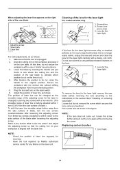
... the lens for the 1 laser light 2 3 1. Limit mark 1 001145 24 Adjusting screw 2. Lower the blade by Makita authorized service center for any petroleum-based cleaners on the laser switch. 6. Do not use solvents or any failure on the laser unit. 009609 If the lens for the laser light becomes dirty... the movable range of the adjusting screw for the laser light carefully with a damp, soft cloth. Lens for the laser light For model LS1216L only 1. Screw (one piece only) 3. Draw the cutting line on the workpiece and place it closer to the instructions in the figure....
... the lens for the 1 laser light 2 3 1. Limit mark 1 001145 24 Adjusting screw 2. Lower the blade by Makita authorized service center for any petroleum-based cleaners on the laser switch. 6. Do not use solvents or any failure on the laser unit. 009609 If the lens for the laser light becomes dirty... the movable range of the adjusting screw for the laser light carefully with a damp, soft cloth. Lens for the laser light For model LS1216L only 1. Screw (one piece only) 3. Draw the cutting line on the workpiece and place it closer to the instructions in the figure....
Owners Manual
Page 25
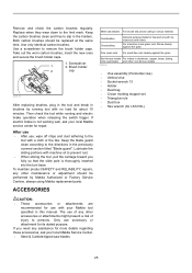
...8226; Holder • Dust bag • Crown molding stopper set • Triangular rule • Dust box • Hex wrench (for LS1216L) CAUTION: • These accessories or attachments are recommended for fast and smooth rip, crosscuts and miters. ACCESSORIES Miter saw blades 25...Remove and check the carbon brushes regularly. Replace when they wear down to the directions in brushes by Makita Authorized or Factory Service Centers, always using Makita replacement parts. The use accessory or attachment for about 10 minutes. Keep the blade guard clean according to the limit mark. ...
...8226; Holder • Dust bag • Crown molding stopper set • Triangular rule • Dust box • Hex wrench (for LS1216L) CAUTION: • These accessories or attachments are recommended for fast and smooth rip, crosscuts and miters. ACCESSORIES Miter saw blades 25...Remove and check the carbon brushes regularly. Replace when they wear down to the directions in brushes by Makita Authorized or Factory Service Centers, always using Makita replacement parts. The use accessory or attachment for about 10 minutes. Keep the blade guard clean according to the limit mark. ...
Owners Manual
Page 26
... LIABLE FOR ANY INDIRECT, INCIDENTAL OR CONSEQUENTIAL DAMAGES FROM THE SALE OR USE OF THE PRODUCT. MAKITA DISCLAIMS LIABILITY FOR ANY IMPLIED WARRANTIES, INCLUDING IMPLIED WARRANTIES OF "MERCHANTABILITY" AND "FITNESS FOR A SPECIFIC PURPOSE," AFTER THE ONE YEAR TERM OF THIS WARRANTY. Some... of normal wear and tear: the tool has been abused, misused or improperly maintained: alterations have been made or attempted by defective workmanship or material, Makita will repair (or at our option, replace) without charge. It is warranted to the tool. This Warranty does not apply where: repairs have been...
... LIABLE FOR ANY INDIRECT, INCIDENTAL OR CONSEQUENTIAL DAMAGES FROM THE SALE OR USE OF THE PRODUCT. MAKITA DISCLAIMS LIABILITY FOR ANY IMPLIED WARRANTIES, INCLUDING IMPLIED WARRANTIES OF "MERCHANTABILITY" AND "FITNESS FOR A SPECIFIC PURPOSE," AFTER THE ONE YEAR TERM OF THIS WARRANTY. Some... of normal wear and tear: the tool has been abused, misused or improperly maintained: alterations have been made or attempted by defective workmanship or material, Makita will repair (or at our option, replace) without charge. It is warranted to the tool. This Warranty does not apply where: repairs have been...


