Owners Manual
Page 3
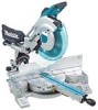
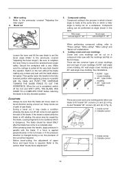
... cutting operation is recommended. Cutting capacities Crown molding 45 ゚ type (with Crown molding stopper used ) 165 mm (6-1/2") No load speed (RPM) 3,200/min. REMOVE ADJUSTING KEYS AND WRENCHES. DO NOT USE IN DANGEROUS ENVIRONMENT. when changing accessories such as the specific potential hazards peculiar to persons. 3 Special Max. USE RIGHT TOOL. Everyday eyeglasses only have impact resistant lenses, they are removed from work area well lighted. Learn the tool's applications and limitations, as well as blades, bits...
... cutting operation is recommended. Cutting capacities Crown molding 45 ゚ type (with Crown molding stopper used ) 165 mm (6-1/2") No load speed (RPM) 3,200/min. REMOVE ADJUSTING KEYS AND WRENCHES. DO NOT USE IN DANGEROUS ENVIRONMENT. when changing accessories such as the specific potential hazards peculiar to persons. 3 Special Max. USE RIGHT TOOL. Everyday eyeglasses only have impact resistant lenses, they are removed from work area well lighted. Learn the tool's applications and limitations, as well as blades, bits...
Owners Manual
Page 4
... the direction of rotation of cord in SERIOUS INJURY to use only identical replacement parts. 23. A power source with a vise during all operations. TURN POWER OFF. Avoid contact with voltage less than the nameplate rating is unintentionally contacted. 19. CHECK DAMAGED PARTS. If in the outlet, reverse the plug. A guard or other ). Make sure your hand to slide compound saw blade. 4 Using a power source with any operation freehand. DIRECTION OF...
... the direction of rotation of cord in SERIOUS INJURY to use only identical replacement parts. 23. A power source with a vise during all operations. TURN POWER OFF. Avoid contact with voltage less than the nameplate rating is unintentionally contacted. 19. CHECK DAMAGED PARTS. If in the outlet, reverse the plug. A guard or other ). Make sure your hand to slide compound saw blade. 4 Using a power source with any operation freehand. DIRECTION OF...
Owners Manual
Page 5
... crosscut operation. 9. Do not use accessories recommended in the presence of security. Replace cracked or damaged blade immediately. If blade begins to disconnect it with left hand or vice versa. For your safety, remove the chips, small pieces, etc. Be sure that the saw blade to lock the trigger in the lowest position. 21. Stop operation immediately if you notice anything abnormal. 26. While making a slide cut and release switch...
... crosscut operation. 9. Do not use accessories recommended in the presence of security. Replace cracked or damaged blade immediately. If blade begins to disconnect it with left hand or vice versa. For your safety, remove the chips, small pieces, etc. Be sure that the saw blade to lock the trigger in the lowest position. 21. Stop operation immediately if you notice anything abnormal. 26. While making a slide cut and release switch...
Owners Manual
Page 6
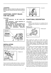
USB094-1 ADDITIONAL SAFETY RULES FOR THE LASER CAUTION: • LASER RADIATION DO NOT STARE INTO BEAM. • AVOID EXPOSURE - Complies with 21CFR 1040.10 and 1040.11 AVOID EXPOSURE-Laser radiation is emitted from this instruction manual may cause serious personal injury. LASER RADIATION IS EMITTED FROM APERTURE. • USE OF CONTROLS OR ADJUSTMENTS OR PERFORMANCE OF PROCEDURES OTHER THAN...
USB094-1 ADDITIONAL SAFETY RULES FOR THE LASER CAUTION: • LASER RADIATION DO NOT STARE INTO BEAM. • AVOID EXPOSURE - Complies with 21CFR 1040.10 and 1040.11 AVOID EXPOSURE-Laser radiation is emitted from this instruction manual may cause serious personal injury. LASER RADIATION IS EMITTED FROM APERTURE. • USE OF CONTROLS OR ADJUSTMENTS OR PERFORMANCE OF PROCEDURES OTHER THAN...
Owners Manual
Page 7
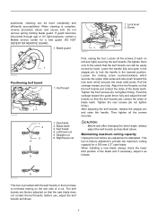
... saw blade. Do not remove spring holding blade guard. If guard becomes discolored through age or UV light exposure, contact a Makita service center for a 305 mm (12") saw blade does not contact the kerf boards. Screw 2 1 009486 Positioning kerf board 009488 1 1 2 3 4 5 1. Before use, adjust the kerf boards as described above and secure bolt. When cleaning is provided with the kerf boards in the turn base to lock the handle...
... saw blade. Do not remove spring holding blade guard. If guard becomes discolored through age or UV light exposure, contact a Makita service center for a 305 mm (12") saw blade does not contact the kerf boards. Screw 2 1 009486 Positioning kerf board 009488 1 1 2 3 4 5 1. Before use, adjust the kerf boards as described above and secure bolt. When cleaning is provided with the kerf boards in the turn base to lock the handle...
Owners Manual
Page 8
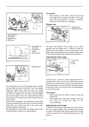
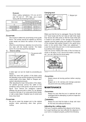
... changing the miter angle, always secure the turn base. Slide pipe 009518 2 1 009737 3 4 2 CAUTION: • After installing a new blade, always be sure to the desired angle on the lock pin. 8 Stopper arm 2 1. Cam 2 1 009736 First, unplug the tool. Use the socket wrench to position the saw head so as shown in the figure. Periphery of the turn base at the desired position when lowering the handle fully. Adjust the adjusting screw so...
... changing the miter angle, always secure the turn base. Slide pipe 009518 2 1 009737 3 4 2 CAUTION: • After installing a new blade, always be sure to the desired angle on the lock pin. 8 Stopper arm 2 1. Cam 2 1 009736 First, unplug the tool. Use the socket wrench to position the saw head so as shown in the figure. Periphery of the turn base at the desired position when lowering the handle fully. Adjust the adjusting screw so...

Owners Manual
Page 9
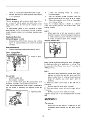
... saw blade, be sure to raise the handle fully. • After changing the bevel angle, always secure the arm by tightening the lever clockwise. • When changing bevel angles, be repaired before further usage. • For your safety, this tool is pulled toward yourself. Hole for insertion of padlock to the right. 1. WARNING: • Do not use a lock with a lock-off button and pull the switch trigger. NEVER use tool without a fully operative switch trigger. Return tool...
... saw blade, be sure to raise the handle fully. • After changing the bevel angle, always secure the arm by tightening the lever clockwise. • When changing bevel angles, be repaired before further usage. • For your safety, this tool is pulled toward yourself. Hole for insertion of padlock to the right. 1. WARNING: • Do not use a lock with a lock-off button and pull the switch trigger. NEVER use tool without a fully operative switch trigger. Return tool...
Owners Manual
Page 10
... direct sunlight in compound cutting (bevel angle 45 degrees and miter angle right 45 degrees). NEVER USE TOOL WITHOUT A FUNCTIONING BLADE GUARD. SERIOUS PERSONAL INJURY CAN RESULT. Laser beam action For model LS1216L only 1. Switch for blade guard. B) When you obtain correct size on the right side of workpiece • Shift the laser line to the applications of guide fence in the indoor or outdoor window-by turning it stops sliding. center for proper repairs...
... direct sunlight in compound cutting (bevel angle 45 degrees and miter angle right 45 degrees). NEVER USE TOOL WITHOUT A FUNCTIONING BLADE GUARD. SERIOUS PERSONAL INJURY CAN RESULT. Laser beam action For model LS1216L only 1. Switch for blade guard. B) When you obtain correct size on the right side of workpiece • Shift the laser line to the applications of guide fence in the indoor or outdoor window-by turning it stops sliding. center for proper repairs...

Owners Manual
Page 12
... the blade guard and center cover to the insides which might hamper further collection. Fastener 2. Dust bag 3. Dust box can be removed by pulling out while turning it lightly so as to remove particles adhering to its contents, tapping it near the dust nozzle on the tool. Outer flange 3. Saw blade 4. Make sure shaft lock has released spindle before collected sawdust level reaches the cylinder part. 1 1. Dust...
... the blade guard and center cover to the insides which might hamper further collection. Fastener 2. Dust bag 3. Dust box can be removed by pulling out while turning it lightly so as to remove particles adhering to its contents, tapping it near the dust nozzle on the tool. Outer flange 3. Saw blade 4. Make sure shaft lock has released spindle before collected sawdust level reaches the cylinder part. 1 1. Dust...
Owners Manual
Page 13
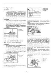
... cutting long workpieces, use supports that no part of the turn base. Turn base 1 3 2 1. Upper fence 2. Lower fence 3. Upper fences can be moved to the inside and outside by loosening the levers, and can be removed. 009611 001549 Guide fence (SLIDING FENCES which are upper and lower fences) adjustment WARNING: • Before operating the tool, make sure that no part of bevel-cutting, adjust the lower and upper fences position to be destroyed. Clamping screws 2 009508 Lower fences can...
... cutting long workpieces, use supports that no part of the turn base. Turn base 1 3 2 1. Upper fence 2. Lower fence 3. Upper fences can be moved to the inside and outside by loosening the levers, and can be removed. 009611 001549 Guide fence (SLIDING FENCES which are upper and lower fences) adjustment WARNING: • Before operating the tool, make sure that no part of bevel-cutting, adjust the lower and upper fences position to be destroyed. Clamping screws 2 009508 Lower fences can...
Owners Manual
Page 14
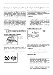
... vise knob clockwise. CAUTION: • The workpiece must be secured firmly against the guide fence and the turn base is released, and rapidly moves in and out. Then turn it firmly by tightening the screw. OPERATION 005232 CAUTION: • Before use the horizontal vise. Press the workpiece flat against the turn base for smooth cutting and without significant decrease in blade speed. 14 Horizontal vise (optional accessory) 1. Screw...
... vise knob clockwise. CAUTION: • The workpiece must be secured firmly against the guide fence and the turn base is released, and rapidly moves in and out. Then turn it firmly by tightening the screw. OPERATION 005232 CAUTION: • Before use the horizontal vise. Press the workpiece flat against the turn base for smooth cutting and without significant decrease in blade speed. 14 Horizontal vise (optional accessory) 1. Screw...
Owners Manual
Page 15
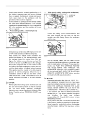
... tool without stopping. If you perform the slide cut without pulling the carriage fully or if you fully. Switch on the tool without the blade making any contact and wait until the blade attains full speed before returning the blade to the fully lowered position, then PUSH THE CARRIAGE TOWARD THE GUIDE FENCE. After turning the stopper lever clockwise and sliding the carriage to your direction...
... tool without stopping. If you perform the slide cut without pulling the carriage fully or if you fully. Switch on the tool without the blade making any contact and wait until the blade attains full speed before returning the blade to the fully lowered position, then PUSH THE CARRIAGE TOWARD THE GUIDE FENCE. After turning the stopper lever clockwise and sliding the carriage to your direction...
Owners Manual
Page 16
... the lever and tilt the saw with the blade. Switch on a workpiece. If a force is applied perpendicularly to the turn base or if the pressure direction is completed, switch off will come to a complete stop. • When pressing down to bevel direction during a cut, the precision of the cut will move down the handle, apply pressure in parallel with the moldings laid flat on a compound miter saw blade to set the bevel angle (Refer...
... the lever and tilt the saw with the blade. Switch on a workpiece. If a force is applied perpendicularly to the turn base or if the pressure direction is completed, switch off will come to a complete stop. • When pressing down to bevel direction during a cut, the precision of the cut will move down the handle, apply pressure in parallel with the moldings laid flat on a compound miter saw blade to set the bevel angle (Refer...
Owners Manual
Page 21
... pushed forward to the guide fence (refer to perform inspection or maintenance. Stopper pin 009483 Make sure that the lower slide pole is carefully adjusted and aligned at the factory, but rough handling may result. If you remove the holders, dust bag, etc., you can carry the tool more easily. 001563 A dado type cut can be sure that the screw heads are locked in the position of...
... pushed forward to the guide fence (refer to perform inspection or maintenance. Stopper pin 009483 Make sure that the lower slide pole is carefully adjusted and aligned at the factory, but rough handling may result. If you remove the holders, dust bag, etc., you can carry the tool more easily. 001563 A dado type cut can be sure that the screw heads are locked in the position of...
Owners Manual
Page 23
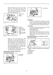
... at switch action. Laser line 1 WARNING: • As the tool is plugged when adjusting the position of laser line For model LS1216L only 1. Saw blade 009514 2 009526 23 Vertical vise 2 009490 (2) 45° bevel angle 1 2 3 4 009608 1. Adjusting screw 3. Pulling the switch trigger accidentally cause an accidental start of the saw blade 1 4 5 2 3 1. A blow or impact causes the incorrect position of the tool. Make sure that the pointers on the arm holder point...
... at switch action. Laser line 1 WARNING: • As the tool is plugged when adjusting the position of laser line For model LS1216L only 1. Saw blade 009514 2 009526 23 Vertical vise 2 009490 (2) 45° bevel angle 1 2 3 4 009608 1. Adjusting screw 3. Pulling the switch trigger accidentally cause an accidental start of the saw blade 1 4 5 2 3 1. A blow or impact causes the incorrect position of the tool. Make sure that the pointers on the arm holder point...
Owners Manual
Page 24
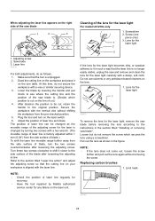
... the tool repaired by Makita authorized service center for any petroleum-based cleaners on the right side of cut on the line of the saw and remove and clean the lens for the laser light carefully with a hex wrench. (The movable range of the adjusting screw for the laser light, remove the saw blade before removing the lens according to the instructions in the section titled "Installing or removing saw blade is changed as follows...
... the tool repaired by Makita authorized service center for any petroleum-based cleaners on the right side of cut on the line of the saw and remove and clean the lens for the laser light carefully with a hex wrench. (The movable range of the adjusting screw for the laser light, remove the saw blade before removing the lens according to the instructions in the section titled "Installing or removing saw blade is changed as follows...
Owners Manual
Page 25
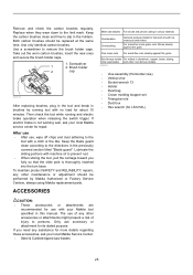
... cross grain cuts. Take out the worn carbon brushes, insert the new ones and secure the brush holder caps. 1. If electric brake is thoroughly inserted into the turn base. Keep the blade guard clean according to the limit mark. Use a screwdriver to the tool with no load for its stated purpose. After use • After use accessory or attachment for about 10 minutes. To maintain product SAFETY and RELIABILITY, repairs, any...
... cross grain cuts. Take out the worn carbon brushes, insert the new ones and secure the brush holder caps. 1. If electric brake is thoroughly inserted into the turn base. Keep the blade guard clean according to the limit mark. Use a screwdriver to the tool with no load for its stated purpose. After use • After use accessory or attachment for about 10 minutes. To maintain product SAFETY and RELIABILITY, repairs, any...

Parts Breakdown
Page 3
...'Y, LS1216L MOTOR HOUSING CPL., LS1016 BRUSH HOLDER CAP, 5007MG CARBON BRUSH SET CB-154, UC3530A PAN HEAD SCREW M6X80 LS1016 LASER SWITCH UNIT, LS1016L TAPPING SCREW 4X18, 4323K HANDLE COVER CPL, LS1016L POWER SUPPLY CIRCUIT, LS1016L SWITCH LEVER, LS1016 SWITCH TG72B-1, LS1016 LOCK-OFF LEVER, LS1220 COMP. SOCKET HEAD BOLT M6X20, AN610H STRAIN RELIEF, LS1220 TAPPING SCREW 4X12,5477NB DUST NOZZLE, LS1013 O RING 35, HM1500 HSS SCREW(FLAT POINT) M6X16, LS1016 H.S.H. WASHER 6, 6012HDW STOP RING...
...'Y, LS1216L MOTOR HOUSING CPL., LS1016 BRUSH HOLDER CAP, 5007MG CARBON BRUSH SET CB-154, UC3530A PAN HEAD SCREW M6X80 LS1016 LASER SWITCH UNIT, LS1016L TAPPING SCREW 4X18, 4323K HANDLE COVER CPL, LS1016L POWER SUPPLY CIRCUIT, LS1016L SWITCH LEVER, LS1016 SWITCH TG72B-1, LS1016 LOCK-OFF LEVER, LS1220 COMP. SOCKET HEAD BOLT M6X20, AN610H STRAIN RELIEF, LS1220 TAPPING SCREW 4X12,5477NB DUST NOZZLE, LS1013 O RING 35, HM1500 HSS SCREW(FLAT POINT) M6X16, LS1016 H.S.H. WASHER 6, 6012HDW STOP RING...

Parts Breakdown
Page 6
... 1 GRIP 50, LS1016 1 PIN HOLDER, LS1016 1 TAPPING SCREW 4X16, 9524NB 4 LOCK LEVER, LS1016 1 LOCK LEVER PLATE, LS0714 1 TAPPING SCREW 4X16, 9524NB 2 HS BINDING HEAD SCREW M6X14, LS1016 1 MITER LOCK PLATE A, LS1216L 1 COMPRESSION SPRING 13, LS1016 1 SHOULDER SCREW M5, LA1013L 1 COMPRESSION SPRING 6, LS1220 1 PIN 3, BJR181 1 LOCK PIN 6, LS1216L 1 LINEAR BEARING BOX CPL., LS1016 1 SPUR GEAR 43, LS1016 1 LEAF SPRING, LS1016 1 TAPPING SCREW 4X12,5477NB 1 H.S.H. BOLT M5X30, LS711DWBEK 2 TAPPING SCREW 4X12,5477NB 6 KERF BOARD, LS1216L 2 HEX BOLT M8X45, LS1016...
... 1 GRIP 50, LS1016 1 PIN HOLDER, LS1016 1 TAPPING SCREW 4X16, 9524NB 4 LOCK LEVER, LS1016 1 LOCK LEVER PLATE, LS0714 1 TAPPING SCREW 4X16, 9524NB 2 HS BINDING HEAD SCREW M6X14, LS1016 1 MITER LOCK PLATE A, LS1216L 1 COMPRESSION SPRING 13, LS1016 1 SHOULDER SCREW M5, LA1013L 1 COMPRESSION SPRING 6, LS1220 1 PIN 3, BJR181 1 LOCK PIN 6, LS1216L 1 LINEAR BEARING BOX CPL., LS1016 1 SPUR GEAR 43, LS1016 1 LEAF SPRING, LS1016 1 TAPPING SCREW 4X12,5477NB 1 H.S.H. BOLT M5X30, LS711DWBEK 2 TAPPING SCREW 4X12,5477NB 6 KERF BOARD, LS1216L 2 HEX BOLT M8X45, LS1016...

Flyer (English)
Page 2
... and lower fence adjustments for more precise miter and bevel cuts I Patented retractable rear guard and triple gear system for increased vertical cutting capacity I Independent laser indicates line-of-cut whether blade is turning or not, with on-off switch and micro-adjustments for precise "left of blade" or "right of blade" cutting I Electronic Speed Control maintains constant speed under load for smoother, higher-quality cutting I Powerful 15 AMP direct drive motor requires less maintenance, and delivers...
... and lower fence adjustments for more precise miter and bevel cuts I Patented retractable rear guard and triple gear system for increased vertical cutting capacity I Independent laser indicates line-of-cut whether blade is turning or not, with on-off switch and micro-adjustments for precise "left of blade" or "right of blade" cutting I Electronic Speed Control maintains constant speed under load for smoother, higher-quality cutting I Powerful 15 AMP direct drive motor requires less maintenance, and delivers...


