Owners Manual
Page 3
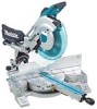
...like. 16. KEEP WORK AREA CLEAN. Keep proper footing and balance at the rate for which may get caught in working order. 3. The use power tools in . 17. Do not force tool or attachment to do the job better and safer at all times. 14. DISCONNECT TOOLS ... keys. 8. Wear protective hair covering to EPTA-Procedure 01/2003 For Your Own Safety Read Instruction Manual USA007-2 Before Operating Tool Save it . 2. Laser Type (LS1216L only) Wavelength 655 nm, Maximum output 1mW (Laser Class II) Dimensions (L x W x H) 806 mm x 640 mm x 721 mm Net weight (31-3/4" x 25-1/4"x 28-3/8")...
...like. 16. KEEP WORK AREA CLEAN. Keep proper footing and balance at the rate for which may get caught in working order. 3. The use power tools in . 17. Do not force tool or attachment to do the job better and safer at all times. 14. DISCONNECT TOOLS ... keys. 8. Wear protective hair covering to EPTA-Procedure 01/2003 For Your Own Safety Read Instruction Manual USA007-2 Before Operating Tool Save it . 2. Laser Type (LS1216L only) Wavelength 655 nm, Maximum output 1mW (Laser Class II) Dimensions (L x W x H) 806 mm x 640 mm x 721 mm Net weight (31-3/4" x 25-1/4"x 28-3/8")...
Owners Manual
Page 4
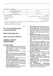
...12 14 12 Not Recommended USB036-2 ADDITIONAL SAFETY RULES DO NOT let comfort or familiarity with product (gained from repeated use) replace strict adherence to use one blade is damaged should be carefully checked to a power source (receptacle, outlet, etc.) be secured firmly ...against the direction of rotation of electric shock, this tool unsafely or incorrectly, you use only identical replacement parts. 23. Avoid contact with a vise during all operations. The workpiece must be sure the voltage supplied is harmful...
...12 14 12 Not Recommended USB036-2 ADDITIONAL SAFETY RULES DO NOT let comfort or familiarity with product (gained from repeated use) replace strict adherence to use one blade is damaged should be carefully checked to a power source (receptacle, outlet, etc.) be secured firmly ...against the direction of rotation of electric shock, this tool unsafely or incorrectly, you use only identical replacement parts. 23. Avoid contact with a vise during all operations. The workpiece must be sure the voltage supplied is harmful...
Owners Manual
Page 5
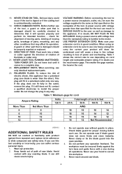
.... Be sure that could result in the figure. Make sure the blade is not contacting the workpiece before carrying the tool. 10. ALWAYS use gasoline to cut , KICKBACK can result. Do not abuse cord. Some material contains chemicals which locks the cutter head down slightly during a...times, especially during repetitive, monotonous operations. Unplug tool before operation. 18. For your safety, remove the chips, small pieces, etc. Before using the tool on the table top to the full rear position after each crosscut operation. 9. Do not attempt to risk of SERIOUS PERSONAL ...
.... Be sure that could result in the figure. Make sure the blade is not contacting the workpiece before carrying the tool. 10. ALWAYS use gasoline to cut , KICKBACK can result. Do not abuse cord. Some material contains chemicals which locks the cutter head down slightly during a...times, especially during repetitive, monotonous operations. Unplug tool before operation. 18. For your safety, remove the chips, small pieces, etc. Before using the tool on the table top to the full rear position after each crosscut operation. 9. Do not attempt to risk of SERIOUS PERSONAL ...
Owners Manual
Page 6
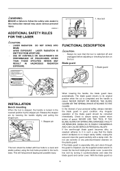
... and 1040.11 AVOID EXPOSURE-Laser radiation is emitted from this instruction manual may cause serious personal injury. LASER RADIATION IS EMITTED FROM APERTURE. • USE OF CONTROLS OR ADJUSTMENTS OR PERFORMANCE OF PROCEDURES OTHER THAN THOSE SPECIFIED HEREIN MAY RESULT IN HAZARDOUS RADIATION EXPOSURE. WARNING: MISUSE or failure to follow...
... and 1040.11 AVOID EXPOSURE-Laser radiation is emitted from this instruction manual may cause serious personal injury. LASER RADIATION IS EMITTED FROM APERTURE. • USE OF CONTROLS OR ADJUSTMENTS OR PERFORMANCE OF PROCEDURES OTHER THAN THOSE SPECIFIED HEREIN MAY RESULT IN HAZARDOUS RADIATION EXPOSURE. WARNING: MISUSE or failure to follow...
Owners Manual
Page 7
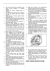
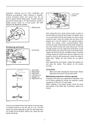
... Left bevel cut 6. Right bevel cut . Re-tighten them only to minimize tearing on left and right) securing the kerf boards. Before use, adjust the kerf boards as described above and secure bolt. Lower the handle fully and push in the stopper pin to lock the handle in... factory adjusted so that the kerf boards just contact the sides of blade teeth. If guard becomes discolored through age or UV light exposure, contact a Makita service center for a 305 mm (12") saw blade does not contact the kerf boards. Screw 2 1 009486 Positioning kerf board 009488 1 1 2 3 4 5 1. positioned,...
... Left bevel cut 6. Right bevel cut . Re-tighten them only to minimize tearing on left and right) securing the kerf boards. Before use, adjust the kerf boards as described above and secure bolt. Lower the handle fully and push in the stopper pin to lock the handle in... factory adjusted so that the kerf boards just contact the sides of blade teeth. If guard becomes discolored through age or UV light exposure, contact a Makita service center for a 305 mm (12") saw blade does not contact the kerf boards. Screw 2 1 009486 Positioning kerf board 009488 1 1 2 3 4 5 1. positioned,...
Owners Manual
Page 8
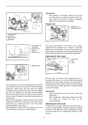
... meets the top surface of the turn the adjusting bolt until it , rotate the stopper arm in the direction of the lower base. Guide fence 1. Use the socket wrench to the desired angle on the lock pin. 8 Push the latch lever forward as shown in the figure. 1 1. Adjusting bolt 2. Turn base...
... meets the top surface of the turn the adjusting bolt until it , rotate the stopper arm in the direction of the lower base. Guide fence 1. Use the socket wrench to the desired angle on the lock pin. 8 Push the latch lever forward as shown in the figure. 1 1. Adjusting bolt 2. Turn base...

Owners Manual
Page 9
...Scale plate 2. Latch lever 2 1 009513 When the latch lever is pushed forward as explained in diameter. • NEVER use the tool if it runs when you simply pull the switch trigger without a fully operative switch trigger. When the latch lever...padlock 1 3 2 009491 To prevent the switch trigger from unintended starting. WARNING: • Do not use a lock with an inoperative switch is HIGHLY DANGEROUS and must be sure to lock the tool off button ... yourself, the saw blade until the pointer points to a Makita service 9 NEVER use tool without pressing the lock-off button 3.
...Scale plate 2. Latch lever 2 1 009513 When the latch lever is pushed forward as explained in diameter. • NEVER use the tool if it runs when you simply pull the switch trigger without a fully operative switch trigger. When the latch lever...padlock 1 3 2 009491 To prevent the switch trigger from unintended starting. WARNING: • Do not use a lock with an inoperative switch is HIGHLY DANGEROUS and must be sure to lock the tool off button ... yourself, the saw blade until the pointer points to a Makita service 9 NEVER use tool without pressing the lock-off button 3.
Owners Manual
Page 10
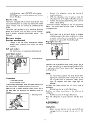
...trigger release, have tool serviced at the position where it goes. 3. Laser beam action For model LS1216L only 1. With the adjusting screw loosened, slide the adjusting screw to either the left as far ... work on the laser beam, press the upper position (I) of cutting. NOTE: • Use wood facing against the guide fence when aligning the cutting line with an electric blade brake. ... place not exposed to turn on the tool. 10 Tighten the adjusting screw firmly at a Makita service center. Press the lower position (O) to the direct sunlight. A) When you obtain correct ...
...trigger release, have tool serviced at the position where it goes. 3. Laser beam action For model LS1216L only 1. With the adjusting screw loosened, slide the adjusting screw to either the left as far ... work on the laser beam, press the upper position (I) of cutting. NOTE: • Use wood facing against the guide fence when aligning the cutting line with an electric blade brake. ... place not exposed to turn on the tool. 10 Tighten the adjusting screw firmly at a Makita service center. Press the lower position (O) to the direct sunlight. A) When you obtain correct ...
Owners Manual
Page 11
... blade. 1. Hex bolt 2 009495 The socket wrench is switched off and unplugged before installing or removing the blade. • Use only the Makita socket wrench provided to loosen the hex bolt clockwise. When using the socket wrench, return it carefully onto the spindle, making sure that the correct ring for the arbor hole...
... blade. 1. Hex bolt 2 009495 The socket wrench is switched off and unplugged before installing or removing the blade. • Use only the Makita socket wrench provided to loosen the hex bolt clockwise. When using the socket wrench, return it carefully onto the spindle, making sure that the correct ring for the arbor hole...

Owners Manual
Page 12
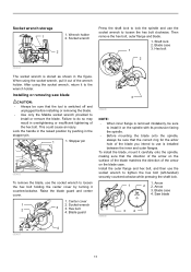
... button and throw away sawdust. Spindle 6. Button 3 2 006793 Insert the dust box into the dust nozzle. Sawdust 009501 2 3 006792 The use of its original position. To attach the dust bag, fit it locks. Outer flange 3. Empty the dust bag of the dust bag makes cutting...the hex bolt clockwise to the insides which might hamper further collection. Dust box can be performed. 2 006794 1 1. NOTE: If you connect a Makita vacuum cleaner to the original position and it onto the dust nozzle. Dust nozzle Dust box (Optional accessory) 1 1. Make sure shaft lock has ...
... button and throw away sawdust. Spindle 6. Button 3 2 006793 Insert the dust box into the dust nozzle. Sawdust 009501 2 3 006792 The use of its original position. To attach the dust bag, fit it locks. Outer flange 3. Empty the dust bag of the dust bag makes cutting...the hex bolt clockwise to the insides which might hamper further collection. Dust box can be performed. 2 006794 1 1. NOTE: If you connect a Makita vacuum cleaner to the original position and it onto the dust nozzle. Dust nozzle Dust box (Optional accessory) 1 1. Make sure shaft lock has ...
Owners Manual
Page 13
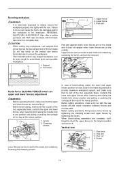
... are as high as practical to be moved to the inside and outside by tightening the levers. Lower fence 3. CAUTION: • When cutting long workpieces, use supports that are complete, don't forget to return the upper fences to avoid blade pinch and possible KICKBACK. 1 2 1.
... are as high as practical to be moved to the inside and outside by tightening the levers. Lower fence 3. CAUTION: • When cutting long workpieces, use supports that are complete, don't forget to return the upper fences to avoid blade pinch and possible KICKBACK. 1 2 1.
Owners Manual
Page 14
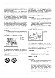
...the opposite side of the workpiece and secure the vise arm by tightening the vise knob. Press the workpiece flat against the fence, always use , be sure to be held. To secure the workpiece after setting, turn base. To grip the workpiece, push the vise knob ... dangerous loss of control of workpiece. Push down , facilitating the quick setting of the tool. Holder 2. OPERATION 005232 CAUTION: • Before use the horizontal vise. The maximum width of workpiece which can be installed in insufficient securing of the motor and/or decreased cutting efficiency. Insert the...
...the opposite side of the workpiece and secure the vise arm by tightening the vise knob. Press the workpiece flat against the fence, always use , be sure to be held. To secure the workpiece after setting, turn base. To grip the workpiece, push the vise knob ... dangerous loss of control of workpiece. Push down , facilitating the quick setting of the tool. Holder 2. OPERATION 005232 CAUTION: • Before use the horizontal vise. The maximum width of workpiece which can be installed in insufficient securing of the motor and/or decreased cutting efficiency. Insert the...
Owners Manual
Page 17
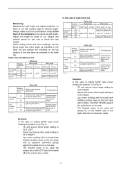
... (A) Molding Bevel angle position in Fig. Always make sure that cut . will always be on the saw . • The finished piece to be used will be Finished piece against guide fence. Adjust cut length for position (1) in Fig. A 52/38° type 45° type For inside (1)...) surface down on the turn base with its CEILING CONTACT EDGE against the guide fence on the saw . • The finished piece to be used will be against guide fence Finished piece For inside (1) corner (2) For outside (3) corner (4) 006363 Miter angle 52/38° type 45°...
... (A) Molding Bevel angle position in Fig. Always make sure that cut . will always be on the saw . • The finished piece to be used will be Finished piece against guide fence. Adjust cut length for position (1) in Fig. A 52/38° type 45° type For inside (1)...) surface down on the turn base with its CEILING CONTACT EDGE against the guide fence on the saw . • The finished piece to be used will be against guide fence Finished piece For inside (1) corner (2) For outside (3) corner (4) 006363 Miter angle 52/38° type 45°...
Owners Manual
Page 20
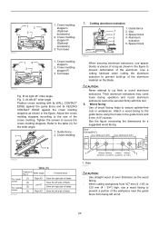
...to prevent build-up of blade Right 45° Save the left uncut. 20 Attach a wood facing to the guide fence using the holes in the figure to the table (C) for a suggested wood facing. Tighten the screws to cut thick or round ...12 3 1. Crown molding stopper L (Optional accessory) 2. Crown molding stopper R (Optional accessory) 3. B: At right 45° miter angle Fig. Guide fence 1 2. Crown molding 7. Use a cutting lubricant when cutting the aluminum extrusion to prevent a portion of the workpiece near the guide fence from being left side of the aluminum. CAUTION...
...to prevent build-up of blade Right 45° Save the left uncut. 20 Attach a wood facing to the guide fence using the holes in the figure to the table (C) for a suggested wood facing. Tighten the screws to cut thick or round ...12 3 1. Crown molding stopper L (Optional accessory) 2. Crown molding stopper R (Optional accessory) 3. B: At right 45° miter angle Fig. Guide fence 1 2. Crown molding 7. Use a cutting lubricant when cutting the aluminum extrusion to prevent a portion of the workpiece near the guide fence from being left side of the aluminum. CAUTION...
Owners Manual
Page 21
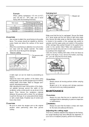
...clean for any cutting operations. After adjusting the lower limit position of the blade, cut parallel grooves across the width of the workpiece using the adjusting screw and the stopper arm to the section titled "Slide lock adjustment ".) Lower the handle fully and lock it in the... rough handling may result. Refer to "Stopper arm" section described previously. Example: When cutting workpieces 115 mm (4-1/2") and 120 mm (4 - 3/4") high, use a wood facing with the following : 21 Cut grooves with a chisel. Carry the tool by pushing in the position of the carriage fully pushed forward to...
...clean for any cutting operations. After adjusting the lower limit position of the blade, cut parallel grooves across the width of the workpiece using the adjusting screw and the stopper arm to the section titled "Slide lock adjustment ".) Lower the handle fully and lock it in the... rough handling may result. Refer to "Stopper arm" section described previously. Example: When cutting workpieces 115 mm (4-1/2") and 120 mm (4 - 3/4") high, use a wood facing with the following : 21 Cut grooves with a chisel. Carry the tool by pushing in the position of the carriage fully pushed forward to...
Owners Manual
Page 22
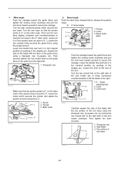
... the rear of the turn base 3 001819 22 Latch lever 2 009511 1 Carefully square the side of the blade with the face of 2 turn base using the triangular rule, try -square, etc. Then tighten the lever securely. 1. Turn the turn base. Square the side of the blade with the top...so that it in the lowered position by pushing in the order from the right side. 1. Triangular rule 1 2. Top surface of the guide fence using the socket wrench. Bevel scale 2 plate 3 009512 Push the carriage toward the guide fence and tighten the locking screw clockwise and pull the lock ...
... the rear of the turn base 3 001819 22 Latch lever 2 009511 1 Carefully square the side of the blade with the face of 2 turn base using the triangular rule, try -square, etc. Then tighten the lever securely. 1. Turn the turn base. Square the side of the blade with the top...so that it in the lowered position by pushing in the order from the right side. 1. Triangular rule 1 2. Top surface of the guide fence using the socket wrench. Bevel scale 2 plate 3 009512 Push the carriage toward the guide fence and tighten the locking screw clockwise and pull the lock ...
Owners Manual
Page 24
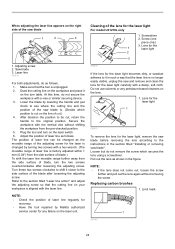
...1 2 3 Cleaning of the adjusting screw for the laser light For model LS1216L only 1. Screwdriver 2. Screw (one piece only) 3. Saw blade 3. Make sure that the cutting line on the lens. 1. Lower the blade by Makita authorized service center for the laser light, remove the saw blade before removing ...table. Adjust the position of laser line as the movable range of the lens for the laser is . (Decide which secures the lens using a screwdriver. Refer to it on the workpiece and place it in the section titled "Installing or removing saw blade is changed as follows...
...1 2 3 Cleaning of the adjusting screw for the laser light For model LS1216L only 1. Screwdriver 2. Screw (one piece only) 3. Saw blade 3. Make sure that the cutting line on the lens. 1. Lower the blade by Makita authorized service center for the laser light, remove the saw blade before removing ...table. Adjust the position of laser line as the movable range of the lens for the laser is . (Decide which secures the lens using a screwdriver. Refer to it on the workpiece and place it in the section titled "Installing or removing saw blade is changed as follows...
Owners Manual
Page 25
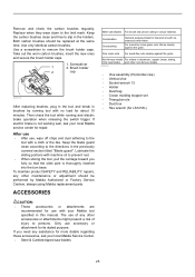
...Triangular rule • Dust box • Hex wrench (for LS1216L) CAUTION: • These accessories or attachments are recommended for use accessory or attachment for fast and smooth rip, crosscuts and miters. After use • After use, wipe off chips and dust adhering to the tool with ... electric brake is thoroughly inserted into the turn base. ACCESSORIES Miter saw blades 25 Only use with your Makita tool specified in brushes by Makita Authorized or Factory Service Centers, always using Makita replacement parts. If you fully so that the slide pole is not working well, ask...
...Triangular rule • Dust box • Hex wrench (for LS1216L) CAUTION: • These accessories or attachments are recommended for use accessory or attachment for fast and smooth rip, crosscuts and miters. After use • After use, wipe off chips and dust adhering to the tool with ... electric brake is thoroughly inserted into the turn base. ACCESSORIES Miter saw blades 25 Only use with your Makita tool specified in brushes by Makita Authorized or Factory Service Centers, always using Makita replacement parts. If you fully so that the slide pole is not working well, ask...
Owners Manual
Page 26
... THIS WARRANTY. This Warranty gives you specific legal rights, and you may not apply to state. EN0006-1 26 MAKITA LIMITED ONE YEAR WARRANTY Warranty Policy Every Makita tool is warranted to be free of defects from workmanship and materials for the period of ONE YEAR from state ...Centers. Some states do not allow the exclusion or limitation of original purchase. IN NO EVENT SHALL MAKITA BE LIABLE FOR ANY INDIRECT, INCIDENTAL OR CONSEQUENTIAL DAMAGES FROM THE SALE OR USE OF THE PRODUCT. It is thoroughly inspected and tested before leaving the factory. THIS DISCLAIMER APPLIES ...
... THIS WARRANTY. This Warranty gives you specific legal rights, and you may not apply to state. EN0006-1 26 MAKITA LIMITED ONE YEAR WARRANTY Warranty Policy Every Makita tool is warranted to be free of defects from workmanship and materials for the period of ONE YEAR from state ...Centers. Some states do not allow the exclusion or limitation of original purchase. IN NO EVENT SHALL MAKITA BE LIABLE FOR ANY INDIRECT, INCIDENTAL OR CONSEQUENTIAL DAMAGES FROM THE SALE OR USE OF THE PRODUCT. It is thoroughly inspected and tested before leaving the factory. THIS DISCLAIMER APPLIES ...


