Owners Manual
Page 4
...result in loss of the tool, a guard or other conditions that may affect its intended function - Do not perform any way. Never reach around saw blade. NEVER STAND ON TOOL. CHECK DAMAGED PARTS. Before further use this appliance has a polarized plug (one way. Feed work into the open... a qualified electrician to use your hand to a power source (receptacle, outlet, etc.) be properly repaired or replaced. 20. Do not operate saw if blade guard does not move freely and close instantly. POLARIZED PLUGS. When using an extension cord, be secured firmly against the direction of rotation...
...result in loss of the tool, a guard or other conditions that may affect its intended function - Do not perform any way. Never reach around saw blade. NEVER STAND ON TOOL. CHECK DAMAGED PARTS. Before further use this appliance has a polarized plug (one way. Feed work into the open... a qualified electrician to use your hand to a power source (receptacle, outlet, etc.) be properly repaired or replaced. 20. Do not operate saw if blade guard does not move freely and close instantly. POLARIZED PLUGS. When using an extension cord, be secured firmly against the direction of rotation...
Owners Manual
Page 5
... Do not abuse cord. Cut only one piece at all times, especially during operation. SAVE THESE INSTRUCTIONS. 5 Check the blade carefully for saw moves up or down is turned on . 23. Replace cracked or damaged blade immediately. Never use vise to these parts could indicate poor installation...chips, small pieces, etc. Be aware that the turn base in the workpiece during a cutting operation, do not continue to fasten the saw and increases potential for this manual. Some material contains chemicals which locks the cutter head down slightly during start-up and stopping. 22....
... Do not abuse cord. Cut only one piece at all times, especially during operation. SAVE THESE INSTRUCTIONS. 5 Check the blade carefully for saw moves up or down is turned on . 23. Replace cracked or damaged blade immediately. Never use vise to these parts could indicate poor installation...chips, small pieces, etc. Be aware that the turn base in the workpiece during a cutting operation, do not continue to fasten the saw and increases potential for this manual. Some material contains chemicals which locks the cutter head down slightly during start-up and stopping. 22....
Owners Manual
Page 6
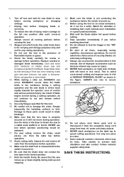
WARNING: MISUSE or failure to follow the safety rules stated in this aperture CAUTION LASER RADIATION DO NOT STARE INTO BEAM Maximum Output Complies with 21CFR 1040.10 and 1040.11 AVOID EXPOSURE-Laser radiation is emitted from this instruction manual may cause serious personal injury. LASER RADIATION IS EMITTED FROM APERTURE. • USE OF CONTROLS OR ADJUSTMENTS OR PERFORMANCE OF PROCEDURES OTHER THAN THOSE SPECIFIED HEREIN MAY RESULT IN HAZARDOUS RADIATION EXPOSURE. USB094-1 ADDITIONAL SAFETY RULES FOR THE LASER CAUTION: • LASER RADIATION DO NOT STARE INTO BEAM. •...
WARNING: MISUSE or failure to follow the safety rules stated in this aperture CAUTION LASER RADIATION DO NOT STARE INTO BEAM Maximum Output Complies with 21CFR 1040.10 and 1040.11 AVOID EXPOSURE-Laser radiation is emitted from this instruction manual may cause serious personal injury. LASER RADIATION IS EMITTED FROM APERTURE. • USE OF CONTROLS OR ADJUSTMENTS OR PERFORMANCE OF PROCEDURES OTHER THAN THOSE SPECIFIED HEREIN MAY RESULT IN HAZARDOUS RADIATION EXPOSURE. USB094-1 ADDITIONAL SAFETY RULES FOR THE LASER CAUTION: • LASER RADIATION DO NOT STARE INTO BEAM. •...
Owners Manual
Page 7
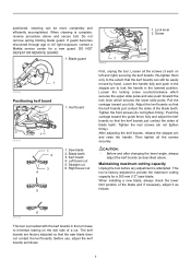
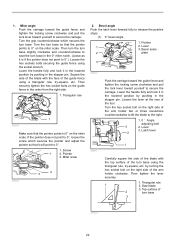
... of the blade and if necessary, adjust it as follows: 7 If guard becomes discolored through age or UV light exposure, contact a Makita service center for a 305 mm (12") saw blade does not contact the kerf boards. Blade teeth 3. Left bevel cut First, unplug the tool. Lower the handle fully and push... in the stopper pin to lock the handle in the turn base to the extent that the saw blade. Kerf board 1. Straight cut . Blade guard 1 009496 1. Kerf board 4. Adjust the kerf boards so that the kerf boards just contact the sides of...
... of the blade and if necessary, adjust it as follows: 7 If guard becomes discolored through age or UV light exposure, contact a Makita service center for a 305 mm (12") saw blade does not contact the kerf boards. Blade teeth 3. Left bevel cut First, unplug the tool. Lower the handle fully and push... in the stopper pin to lock the handle in the turn base to the extent that the saw blade. Kerf board 1. Straight cut . Blade guard 1 009496 1. Kerf board 4. Adjust the kerf boards so that the kerf boards just contact the sides of...
Owners Manual
Page 8
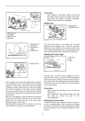
... top surface of the turn base at the point where the front face of the guide fence meets the top surface of the saw blade as to position the saw head so as shown in the figure fully while supporting the weight of the turn the grip to 90° counterclockwise to...
... top surface of the turn base at the point where the front face of the guide fence meets the top surface of the saw blade as to position the saw head so as shown in the figure fully while supporting the weight of the turn the grip to 90° counterclockwise to...

Owners Manual
Page 9
...use tool without a fully operative switch trigger. A hole is pulled toward yourself. Lock lever 2. Scale plate 2. CAUTION: • When tilting the saw blade can be locked at the right and left slightly after loosening the lever and press the releasing button. NEVER use a lock with a lock-off...the "Positioning kerf boards" section. 1 009496 To lock the lower slide pole, pull the lock lever toward yourself, the saw blade until the pointer points to a Makita service 9 Return tool to the desired angle on the bevel scale. When the latch lever is equipped with a shank ...
...use tool without a fully operative switch trigger. A hole is pulled toward yourself. Lock lever 2. Scale plate 2. CAUTION: • When tilting the saw blade can be locked at the right and left slightly after loosening the lever and press the releasing button. NEVER use a lock with a lock-off...the "Positioning kerf boards" section. 1 009496 To lock the lower slide pole, pull the lock lever toward yourself, the saw blade until the pointer points to a Makita service 9 Return tool to the desired angle on the bevel scale. When the latch lever is equipped with a shank ...
Owners Manual
Page 10
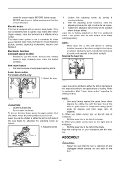
.... Press the lower position (O) to quickly stop blade after switch trigger release, have tool serviced at a Makita service center. NEVER USE TOOL WITHOUT A FUNCTIONING BLADE GUARD. Electronic function Constant speed control • Possible ... relocate the work on the tool. 10 SERIOUS PERSONAL INJURY CAN RESULT. Laser beam action For model LS1216L only 1. Align the cutting line on the right side of workpiece • Shift the laser line to... • Always be shifted to the applications of the saw blade by adjusting the adjusting screw as it is switched off button.
.... Press the lower position (O) to quickly stop blade after switch trigger release, have tool serviced at a Makita service center. NEVER USE TOOL WITHOUT A FUNCTIONING BLADE GUARD. Electronic function Constant speed control • Possible ... relocate the work on the tool. 10 SERIOUS PERSONAL INJURY CAN RESULT. Laser beam action For model LS1216L only 1. Align the cutting line on the right side of workpiece • Shift the laser line to... • Always be shifted to the applications of the saw blade by adjusting the adjusting screw as it is switched off button.
Owners Manual
Page 11
...3. Stopper pin 009483 To remove the blade, use is switched off and unplugged before installing or removing the blade. • Use only the Makita socket wrench provided to do so may result in overtightening or insufficient tightening of the wrench holder. Center cover 1 2. Arrow 1 2 2. Installing or ...removing saw blade CAUTION: • Always be sure that the tool is installed between the inner and outer flanges. After using the socket wrench, ...
...3. Stopper pin 009483 To remove the blade, use is switched off and unplugged before installing or removing the blade. • Use only the Makita socket wrench provided to do so may result in overtightening or insufficient tightening of the wrench holder. Center cover 1 2. Arrow 1 2 2. Installing or ...removing saw blade CAUTION: • Always be sure that the tool is installed between the inner and outer flanges. After using the socket wrench, ...

Owners Manual
Page 12
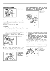
... pin. Empty the dust bag of the dust bag makes cutting operations clean and dust collection easy. NOTE: If you connect a Makita vacuum cleaner to secure the center cover. Make sure shaft lock has released spindle before collected sawdust level reaches the cylinder part.... 1 1. Saw blade 4. Ring Return the blade guard and center cover to your saw, more efficient and cleaner operations can be performed. Release the handle from the tool and pull the fastener out...
... pin. Empty the dust bag of the dust bag makes cutting operations clean and dust collection easy. NOTE: If you connect a Makita vacuum cleaner to secure the center cover. Make sure shaft lock has released spindle before collected sawdust level reaches the cylinder part.... 1 1. Saw blade 4. Ring Return the blade guard and center cover to your saw, more efficient and cleaner operations can be performed. Release the handle from the tool and pull the fastener out...
Owners Manual
Page 13
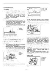
... way at the lowest position. Vise knob 2. Securing workpiece WARNING: • It is extremely important to always secure the workpiece properly and tightly with the saw turned off and check clearance between fences and moving parts. Lower fence 3. Turn base 1 3 2 1. Vise arm 3. Support 2. Upper fences can be moved to the inside...
... way at the lowest position. Vise knob 2. Securing workpiece WARNING: • It is extremely important to always secure the workpiece properly and tightly with the saw turned off and check clearance between fences and moving parts. Lower fence 3. Turn base 1 3 2 1. Vise arm 3. Support 2. Upper fences can be moved to the inside...
Owners Manual
Page 15
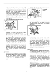
... , FIRST PULL THE CARRIAGE TOWARD YOU FULLY and press down with force or if lateral force is applied, the blade will vibrate and leave a mark (saw mark) in the workpiece and the precision of the blade. Slide (push) cutting (cutting wide workpieces) 1. Then gently lower the handle to the fully lowered...
... , FIRST PULL THE CARRIAGE TOWARD YOU FULLY and press down with force or if lateral force is applied, the blade will vibrate and leave a mark (saw mark) in the workpiece and the precision of the blade. Slide (push) cutting (cutting wide workpieces) 1. Then gently lower the handle to the fully lowered...
Owners Manual
Page 16
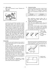
... the previously covered "Adjusting the miter angle". 4. Outside corner (1) (2) (2) (1) (4) (3) 2 (2) (1) (1) (2) 001557 16 Keep hands out of path of saw blade to set the bevel angle (Refer to fit "Inside" 90° corners ((1) and (2) in which is dangerous. A) and "Outside" 90° corners...type cove molding 1 2 3 001555 There are crown and cove molding joints which a bevel angle is required. Switch on a compound miter saw with the blade. There are made at angle shown in parallel with a vise. Miter cutting Refer to "Press cutting", "Slide cutting",...
... the previously covered "Adjusting the miter angle". 4. Outside corner (1) (2) (2) (1) (4) (3) 2 (2) (1) (1) (2) 001557 16 Keep hands out of path of saw blade to set the bevel angle (Refer to fit "Inside" 90° corners ((1) and (2) in which is dangerous. A) and "Outside" 90° corners...type cove molding 1 2 3 001555 There are crown and cove molding joints which a bevel angle is required. Switch on a compound miter saw with the blade. There are made at angle shown in parallel with a vise. Miter cutting Refer to "Press cutting", "Slide cutting",...
Owners Manual
Page 17
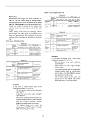
...cut has been made . Always use several pieces for position (1) in the table (A) and position the moldings on the top surface of the saw angles. When cutting crown and cove moldings, set the bevel angle and miter angle as indicated in Fig. A 52/38° type 45&#...type 45° type For inside (1) corner (2) For outside against guide fence. (3) Finished piece will be Finished piece against the guide fence on the saw . • The finished piece to desired length. A Molding edge against the guide fence on the corner Ceiling contact edge should be For outside (3) ...
...cut has been made . Always use several pieces for position (1) in the table (A) and position the moldings on the top surface of the saw angles. When cutting crown and cove moldings, set the bevel angle and miter angle as indicated in Fig. A 52/38° type 45&#...type 45° type For inside (1) corner (2) For outside against guide fence. (3) Finished piece will be Finished piece against the guide fence on the saw . • The finished piece to desired length. A Molding edge against the guide fence on the corner Ceiling contact edge should be For outside (3) ...

Owners Manual
Page 18
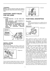
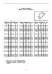
Compound Miter Saw Miter and Bevel Angle Settings Ceiling 52° 38° Wall Wall to Crown Molding Angle: 52/38 degrees Wall Angle Bevel Angle Miter Angle (...
Compound Miter Saw Miter and Bevel Angle Settings Ceiling 52° 38° Wall Wall to Crown Molding Angle: 52/38 degrees Wall Angle Bevel Angle Miter Angle (...
Owners Manual
Page 19
... 161 6.7 6.7 162 6.4 6.4 163 6.0 6.0 164 5.6 5.7 165 5.3 5.3 166 4.9 5.0 167 4.6 4.6 168 4.2 4.3 169 3.9 3.9 170 3.5 3.5 171 3.2 3.2 172 2.8 2.8 173 2.5 2.5 174 2.1 2.1 175 1.8 1.8 176 1.4 1.4 177 1.1 1.1 178 0.7 0.7 179 0.4 0.4 180 0.0 0.0 19 Compound Miter Saw Miter and Bevel Angle Settings Ceiling 45° 45° Wall Wall to Crown Molding Angle: 45 degrees Wall Angle Bevel Angle Miter Angle (deg....3 14.8 140 14.0 14.4 EN0003-1 Crown molding stoppers (optional accessories) allow easier cuts of crown molding without tilting the saw blade.
... 161 6.7 6.7 162 6.4 6.4 163 6.0 6.0 164 5.6 5.7 165 5.3 5.3 166 4.9 5.0 167 4.6 4.6 168 4.2 4.3 169 3.9 3.9 170 3.5 3.5 171 3.2 3.2 172 2.8 2.8 173 2.5 2.5 174 2.1 2.1 175 1.8 1.8 176 1.4 1.4 177 1.1 1.1 178 0.7 0.7 179 0.4 0.4 180 0.0 0.0 19 Compound Miter Saw Miter and Bevel Angle Settings Ceiling 45° 45° Wall Wall to Crown Molding Angle: 45 degrees Wall Angle Bevel Angle Miter Angle (deg....3 14.8 140 14.0 14.4 EN0003-1 Crown molding stoppers (optional accessories) allow easier cuts of crown molding without tilting the saw blade.
Owners Manual
Page 22
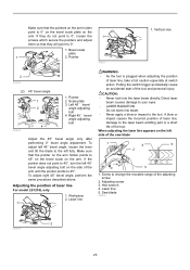
Triangular rule 1 009509 Make sure that the pointer points to 0° on the miter scale. Lever 3. Saw blade 3. Turn the turn base so that the pointer points to 0° on the guide fence in the stopper pin. Bevel angle Push the latch ...
Triangular rule 1 009509 Make sure that the pointer points to 0° on the miter scale. Lever 3. Saw blade 3. Turn the turn base so that the pointer points to 0° on the guide fence in the stopper pin. Bevel angle Push the latch ...
Owners Manual
Page 23
.... Adjusting screw 3. Make sure that the pointer on the arm holder points to 45° on the bevel scale on the left side of the saw blade 1 4 5 2 3 1. If the pointer does not point to 45°, turn the left fully. Workpiece 2. Vertical vise 2 009490 (2) 45° bevel angle 1 2 3 4 009608 1. Pointer 2. To... wrench 4. To adjust left 45° bevel angle, loosen the lever and tilt the blade to change the movable range of laser line For model LS1216L only 1. Saw blade 009514 2 009526 23
.... Adjusting screw 3. Make sure that the pointer on the arm holder points to 45° on the bevel scale on the left side of the saw blade 1 4 5 2 3 1. If the pointer does not point to 45°, turn the left fully. Workpiece 2. Vertical vise 2 009490 (2) 45° bevel angle 1 2 3 4 009608 1. Pointer 2. To... wrench 4. To adjust left 45° bevel angle, loosen the lever and tilt the blade to change the movable range of laser line For model LS1216L only 1. Saw blade 009514 2 009526 23
Owners Manual
Page 24
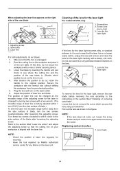
... the laser light 1 009610 To remove the lens for the laser light, remove the saw blade before removing the lens according to the side surface of the lens for the laser light For model LS1216L only 1. Limit mark 1 001145 24 Screwdriver 2. Draw the cutting line on the workpiece... 1 2 3 Cleaning of the blade after loosening the adjusting screw. Laser line 009515 For both adjustments, do as follows. Lower the blade by Makita authorized service center for the 1 laser light 2 3 1. NOTE: • Check the position of the adjusting screw for the laser is unplugged. 2. ...
... the laser light 1 009610 To remove the lens for the laser light, remove the saw blade before removing the lens according to the side surface of the lens for the laser light For model LS1216L only 1. Limit mark 1 001145 24 Screwdriver 2. Draw the cutting line on the workpiece... 1 2 3 Cleaning of the blade after loosening the adjusting screw. Laser line 009515 For both adjustments, do as follows. Lower the blade by Makita authorized service center for the 1 laser light 2 3 1. NOTE: • Check the position of the adjusting screw for the laser is unplugged. 2. ...
Owners Manual
Page 25
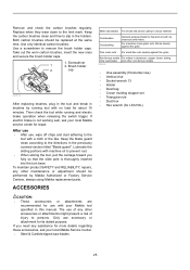
... switch trigger. Lubricate the sliding portions with a cloth or the like. ACCESSORIES Miter saw blades 25 For smoother cross grain cuts. Use only identical carbon brushes. The use...; Crown molding stopper set • Triangular rule • Dust box • Hex wrench (for LS1216L) CAUTION: • These accessories or attachments are recommended for use with no load for its stated ... RELIABILITY, repairs, any assistance for more details regarding these accessories, ask your local Makita service center for fast and smooth rip, crosscuts and miters. If you fully so...
... switch trigger. Lubricate the sliding portions with a cloth or the like. ACCESSORIES Miter saw blades 25 For smoother cross grain cuts. Use only identical carbon brushes. The use...; Crown molding stopper set • Triangular rule • Dust box • Hex wrench (for LS1216L) CAUTION: • These accessories or attachments are recommended for use with no load for its stated ... RELIABILITY, repairs, any assistance for more details regarding these accessories, ask your local Makita service center for fast and smooth rip, crosscuts and miters. If you fully so...

Flyer (English)
Page 1
... system features upper and lower fence adjustments for more precise cuts DURABILITY Models LS1216L / LS1216LX Powerful 15 AMP direct drive motor requires less maintenance than belt driven saws LARGE AND ACCURATE CUTS makitatools.com 12" DUAL SLIDE COMPOUND MITER SAW LARGE CUTTING CAPACITY Large Cutting Capacity Up to 8" Crown Molding (Nested), 6-1/2" Baseboard (Vertical...
... system features upper and lower fence adjustments for more precise cuts DURABILITY Models LS1216L / LS1216LX Powerful 15 AMP direct drive motor requires less maintenance than belt driven saws LARGE AND ACCURATE CUTS makitatools.com 12" DUAL SLIDE COMPOUND MITER SAW LARGE CUTTING CAPACITY Large Cutting Capacity Up to 8" Crown Molding (Nested), 6-1/2" Baseboard (Vertical...


