Owners Manual
Page 5
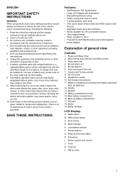
... G. Install in use . 2. Unplug this instruction manual and the charger instruction manual carefully before use , keep it away from one type of fire. 9. Preset stations 6. Clock K. Volume and Tuning controls 8. Scan tuning D. Band Indicator E. Buzzer alarm set 4. Main battery compartment 16. There is an increased risk of fire, electric shock, and personal injury, including the following: 1. ENGLISH IMPORTANT SAFETY INSTRUCTIONS WARNING: When using electric tools, basic safety precautions...
... G. Install in use . 2. Unplug this instruction manual and the charger instruction manual carefully before use , keep it away from one type of fire. 9. Preset stations 6. Clock K. Volume and Tuning controls 8. Scan tuning D. Band Indicator E. Buzzer alarm set 4. Main battery compartment 16. There is an increased risk of fire, electric shock, and personal injury, including the following: 1. ENGLISH IMPORTANT SAFETY INSTRUCTIONS WARNING: When using electric tools, basic safety precautions...
Owners Manual
Page 6
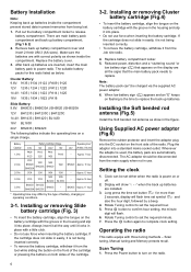
... | BH2420 The following tables indicate the operating time on the battery cartridge with the groove in use force when inserting the battery cartridge. Volume) - Installing or removing Slide battery cartridge (Fig. 3) • To insert the battery cartridge, align the tongue on a single charge. Clock can 't be set symbol and also the hour digit, followed by the type of the cartridge. 3-2. Installing the Soft bended rod...
... | BH2420 The following tables indicate the operating time on the battery cartridge with the groove in use force when inserting the battery cartridge. Volume) - Installing or removing Slide battery cartridge (Fig. 3) • To insert the battery cartridge, align the tongue on a single charge. Clock can 't be set symbol and also the hour digit, followed by the type of the cartridge. 3-2. Installing the Soft bended rod...

Owners Manual
Page 7
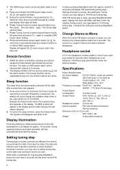
... operate the radio next to computer screen and other equipment which will up search and stop automatically when it finds a radio station. 4. Press and release Scan button (long press Scan button more than 2 seconds will activate time setting), LCD display will flash Scan symbol and the radio will cause interference to turn on the radio. 2. Manual Tuning 1. A single rotary...
... operate the radio next to computer screen and other equipment which will up search and stop automatically when it finds a radio station. 4. Press and release Scan button (long press Scan button more than 2 seconds will activate time setting), LCD display will flash Scan symbol and the radio will cause interference to turn on the radio. 2. Manual Tuning 1. A single rotary...
Owners Manual
Page 8
... AM (MW) and flash 9 kHz. While radio is switched off, long pressing Step/Band button for more than 2 seconds will disappear and radio is off the radio after a preset time has elapsed. 1. Complete the setting by a beep. Specifications: Power Requirements AC power adaptor DC12V 700mA, center pin positive Battery UM-3 (AA size) x 2 for more than 2 seconds followed by a beep...
... AM (MW) and flash 9 kHz. While radio is switched off, long pressing Step/Band button for more than 2 seconds will disappear and radio is off the radio after a preset time has elapsed. 1. Complete the setting by a beep. Specifications: Power Requirements AC power adaptor DC12V 700mA, center pin positive Battery UM-3 (AA size) x 2 for more than 2 seconds followed by a beep...
Parts Breakdown
Page 2
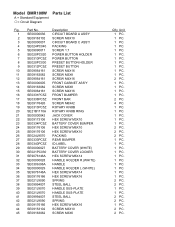
Model BMR100W Parts List A = Standard Equipment 〇= Circuit Diagram Fig. Part No. Description 1 SE00000036 CIRCUIT BOARD A ASS'Y 2 SE09163102 SCREW M3X10 3 SE00000037 CIRCUIT BOARD C ASS'Y 4 SE024PC040 PACKING 5 SE09090011 SCREW 1.7 6 SE020PC020 POWER BUTTON HOLDER 7 SE0310PC5Z POWER BUTTON 8 SE020PC030 PRESET BUTTON HOLDER 9 SE0312PC5Z PRESET BUTTON 10 SE09064161 SCREW M4X16 11 SE09163082 SCREW M3X8 12 SE09064161 SCREW M4X16 13 SE00000005 FRONT CABINET ASS'Y 14 SE09163082 SCREW M3X8 15 SE09064161 SCREW M4X16 16 SE0331PC5Z FRONT BUMPER 17...
Model BMR100W Parts List A = Standard Equipment 〇= Circuit Diagram Fig. Part No. Description 1 SE00000036 CIRCUIT BOARD A ASS'Y 2 SE09163102 SCREW M3X10 3 SE00000037 CIRCUIT BOARD C ASS'Y 4 SE024PC040 PACKING 5 SE09090011 SCREW 1.7 6 SE020PC020 POWER BUTTON HOLDER 7 SE0310PC5Z POWER BUTTON 8 SE020PC030 PRESET BUTTON HOLDER 9 SE0312PC5Z PRESET BUTTON 10 SE09064161 SCREW M4X16 11 SE09163082 SCREW M3X8 12 SE09064161 SCREW M4X16 13 SE00000005 FRONT CABINET ASS'Y 14 SE09163082 SCREW M3X8 15 SE09064161 SCREW M4X16 16 SE0331PC5Z FRONT BUMPER 17...

Parts Breakdown
Page 3
.... 53 SE09163452 SCREW M3X45 2 PC. 54 SE0308PC5Z BATTERY COVER LOCKER 1 PC. 55 SE0314PC5Z LOCKER HINGER 1 PC. 56 SE021PC040 LOCKER FIXER PIN 79.5 1 PC. 57 SE00000033 ROD ANT 1 PC. 58 SE021J9032 ROD ANT HOLDER 1 PC. 59 SE024J9050 PACKING 1 PC. 60 SE021PC050 LOCKER FIXER PIN 63.8 1 PC. 61 SE021PC100 ROD ANT TERMINAL 1 PC. 62 SE021P0020 NUT 1 PC. 63...
.... 53 SE09163452 SCREW M3X45 2 PC. 54 SE0308PC5Z BATTERY COVER LOCKER 1 PC. 55 SE0314PC5Z LOCKER HINGER 1 PC. 56 SE021PC040 LOCKER FIXER PIN 79.5 1 PC. 57 SE00000033 ROD ANT 1 PC. 58 SE021J9032 ROD ANT HOLDER 1 PC. 59 SE024J9050 PACKING 1 PC. 60 SE021PC050 LOCKER FIXER PIN 63.8 1 PC. 61 SE021PC100 ROD ANT TERMINAL 1 PC. 62 SE021P0020 NUT 1 PC. 63...


