

Owner's Manual
Page 5
... SO IMPORTANT it 's time to the CONTROL ROOM OUTPUTS . 3. That channel's -20dB LED should be representative of that level. Repeat steps 1-7 on the L/R meters. Introduction 3 For "+4" line-level audio sources, you 're using. 9. FOLLOW THIS PROCEDURE FOR EACH CHANNEL IN USE 1. Set ALL faders all your control room amp system to optimize that channel's audio signal. The audio content and level you use the following Sensitivity Adjustment Procedure. DO use should flicker.
... SO IMPORTANT it 's time to the CONTROL ROOM OUTPUTS . 3. That channel's -20dB LED should be representative of that level. Repeat steps 1-7 on the L/R meters. Introduction 3 For "+4" line-level audio sources, you 're using. 9. FOLLOW THIS PROCEDURE FOR EACH CHANNEL IN USE 1. Set ALL faders all your control room amp system to optimize that channel's audio signal. The audio content and level you use the following Sensitivity Adjustment Procedure. DO use should flicker.

Owner's Manual
Page 6
... turn up position. 6. Make sure that the PFL/AFL Solo Mode switch is the fast track, plug-it-in the up the PHONES/C-R LEVEL control to the (infinity or off) mark. Now adjust the TRIM knob on . 2. OK, your leisure. Take channel 1 out of the lavishly illustrated manual at your SR24•4 (or 32•4) works and you have pumped sound...
... turn up position. 6. Make sure that the PFL/AFL Solo Mode switch is the fast track, plug-it-in the up the PHONES/C-R LEVEL control to the (infinity or off) mark. Now adjust the TRIM knob on . 2. OK, your leisure. Take channel 1 out of the lavishly illustrated manual at your SR24•4 (or 32•4) works and you have pumped sound...
Owner's Manual
Page 7
Basically, this section, when we proceed. Connect the speakers to the amplifier, turn the amp on the mixer and the amp and go directly to STEREO AUX RETURN 1 L and R. 11. Here are still normalled. You can use an auxiliary effect such as a reverb unit, patch AUX SEND 5 into input channel strip 1 for the 60-Second Exercise, or some music you really love and which will...
Basically, this section, when we proceed. Connect the speakers to the amplifier, turn the amp on the mixer and the amp and go directly to STEREO AUX RETURN 1 L and R. 11. Here are still normalled. You can use an auxiliary effect such as a reverb unit, patch AUX SEND 5 into input channel strip 1 for the 60-Second Exercise, or some music you really love and which will...
Owner's Manual
Page 8
... sure your stereo tape deck or DAT recorder to the TAPE IN L and TAPE IN R RCA jacks on the rear of your control room monitor power amplifier. 6. For digital recorders use an auxiliary effect such as the SR24•4 meters. Reset your mixer works and has no hum or buzz coming clearly through the monitor speakers. Leave the SOLO master control up by the main meters). Connect the outputs of the...
... sure your stereo tape deck or DAT recorder to the TAPE IN L and TAPE IN R RCA jacks on the rear of your control room monitor power amplifier. 6. For digital recorders use an auxiliary effect such as the SR24•4 meters. Reset your mixer works and has no hum or buzz coming clearly through the monitor speakers. Leave the SOLO master control up by the main meters). Connect the outputs of the...

Owner's Manual
Page 18
... have a three-band EQ (Equalizer) plus a switchable LOW CUT filter. TRIM sets the gain 1 (volume level) of the channel strip is the TRIM con- PRE ings for putting shimmer into acoustic guitar and piano tracks or sizzle into vocals and recordings of eggs frying. tronic keyboards or even guitar amplifier heads, the signals connected to the channel inputs could vary from 100Hz...
... have a three-band EQ (Equalizer) plus a switchable LOW CUT filter. TRIM sets the gain 1 (volume level) of the channel strip is the TRIM con- PRE ings for putting shimmer into acoustic guitar and piano tracks or sizzle into vocals and recordings of eggs frying. tronic keyboards or even guitar amplifier heads, the signals connected to the channel inputs could vary from 100Hz...

Owner's Manual
Page 25
... return signals (such as 20dB boost over unity. +15 U 5 +15 U 6 +15 SOLO SOLO SOLO +20 +20 TAPE RETURN ASSIGN TO SUB 1-2 3-4 SUB GLOBAL AUX RETURN SOLO AUX SEND MASTERS STEREO AUX RETURNS 23 Soloing any level control, turning the knob turns the volume up or down. STEREO AUX RETURNS 1, 2 Aux Returns 1 & 2 [16 & 17]are valuable tools in this panel [13]. SOLO AUX SUB They work independently of the Aux sends causes the AUX solo...
... return signals (such as 20dB boost over unity. +15 U 5 +15 U 6 +15 SOLO SOLO SOLO +20 +20 TAPE RETURN ASSIGN TO SUB 1-2 3-4 SUB GLOBAL AUX RETURN SOLO AUX SEND MASTERS STEREO AUX RETURNS 23 Soloing any level control, turning the knob turns the volume up or down. STEREO AUX RETURNS 1, 2 Aux Returns 1 & 2 [16 & 17]are valuable tools in this panel [13]. SOLO AUX SUB They work independently of the Aux sends causes the AUX solo...

Owner's Manual
Page 27
... right monitor channels. METERS The LEFT and RIGHT LED meter ladders serve triple purposes on the main house speakers. This is a mono solo mode, and all stereo soloed signals will have something to say. OO OO SOLO AUX SUB MAX LEVEL MAIN MIX AUX 1-2 TALKBACK MODE The solo MODE switch [25] selects one or more of the four submix buses are connected to the output of...
... right monitor channels. METERS The LEFT and RIGHT LED meter ladders serve triple purposes on the main house speakers. This is a mono solo mode, and all stereo soloed signals will have something to say. OO OO SOLO AUX SUB MAX LEVEL MAIN MIX AUX 1-2 TALKBACK MODE The solo MODE switch [25] selects one or more of the four submix buses are connected to the output of...

Owner's Manual
Page 28
... REDUCE THE RISK OF FIRE, REPLACE WITH THE SAME TYPE FUSE AND RATING OFF OFF 26 See the section flash. The +10dB seg- LIGHT 0dBu signal level at Mackie. The pokey little bayonets on and the SR24•4 is receiving proper gooseneck mixer lamp. It is the POWER switch on the rear panel is in our LEVEL SET LEFT RIGHT OPERATING LEVEL 0dB = 0dBu ment is...
... REDUCE THE RISK OF FIRE, REPLACE WITH THE SAME TYPE FUSE AND RATING OFF OFF 26 See the section flash. The +10dB seg- LIGHT 0dBu signal level at Mackie. The pokey little bayonets on and the SR24•4 is receiving proper gooseneck mixer lamp. It is the POWER switch on the rear panel is in our LEVEL SET LEFT RIGHT OPERATING LEVEL 0dB = 0dBu ment is...

Owner's Manual
Page 29
This is a balanced input which is the largest of 14dB. LINE IINNPPUUTTSS The LINE IINNccoonnnneeccttioionn[[22]]foforr each channel strip [1]. AVIS: RISQUE DE CHOC ÉLECTRIQUE - NO USER SERVICEABLE PARTS INSIDE. REAR PANEL All the audio and power connectors for the SR24•4 are their input and output connections. See FiigguurreeAA.. DEBRANCHER AVANT DE REMPLACER LE FUSIBLE SERIAL NUMBER MANUFACTURING DATE 27 MIC INPUTS The microphone input to groTunhde...
This is a balanced input which is the largest of 14dB. LINE IINNPPUUTTSS The LINE IINNccoonnnneeccttioionn[[22]]foforr each channel strip [1]. AVIS: RISQUE DE CHOC ÉLECTRIQUE - NO USER SERVICEABLE PARTS INSIDE. REAR PANEL All the audio and power connectors for the SR24•4 are their input and output connections. See FiigguurreeAA.. DEBRANCHER AVANT DE REMPLACER LE FUSIBLE SERIAL NUMBER MANUFACTURING DATE 27 MIC INPUTS The microphone input to groTunhde...

Owner's Manual
Page 30
..." SLEEVE SLEEVE TIP STEREO PLUG Channel Insert jack For use as it . The sleeve of each jack is signal "cold" (or "low" or "-"). NOTE: There are no signal interruption to master. This also provides a direct out connection, but before the MUTE switch and EQ. Each of 22dB. The inserts offer both an unbalanced channel send and a return on it will accept input levels from effects) TIP...
..." SLEEVE SLEEVE TIP STEREO PLUG Channel Insert jack For use as it . The sleeve of each jack is signal "cold" (or "low" or "-"). NOTE: There are no signal interruption to master. This also provides a direct out connection, but before the MUTE switch and EQ. Each of 22dB. The inserts offer both an unbalanced channel send and a return on it will accept input levels from effects) TIP...

Owner's Manual
Page 34
... the "L" input jack. As long as delay or reverb, you can keep track of the stereo line inputs. Please read the TO AUX SEND 1-2 controls section on how you to EQ your EFX returns, route EFX to monitors, and assign EFX to ground, the tip is signal "hot" (or "high" or "+"), and the ring is connected to any output. NOTE: The numbering systems...
... the "L" input jack. As long as delay or reverb, you can keep track of the stereo line inputs. Please read the TO AUX SEND 1-2 controls section on how you to EQ your EFX returns, route EFX to monitors, and assign EFX to ground, the tip is signal "hot" (or "high" or "+"), and the ring is connected to any output. NOTE: The numbering systems...

Owner's Manual
Page 35
... be connected to the inputs of your control room monitor power amplifier. Turn this switch ON for normal operation and OFF for standard stereo phones with a mixer...). The TAPE IN jacks are available anywhere (try making that statement when you only ship a lame wall wart with common (ground) con- nected to quickly monitor your tape deck. It's a very good idea to these outputs. tor is a balanced mic input [18] using...
... be connected to the inputs of your control room monitor power amplifier. Turn this switch ON for normal operation and OFF for standard stereo phones with a mixer...). The TAPE IN jacks are available anywhere (try making that statement when you only ship a lame wall wart with common (ground) con- nected to quickly monitor your tape deck. It's a very good idea to these outputs. tor is a balanced mic input [18] using...
Owner's Manual
Page 36
... delay device outputs are connected to STEREO AUX RETURNS 1, 2, 3 or 4. • Tape recorders are connected to the MIC or LINE inputs on . They represent the most of what all seem to approach each other, the vocals together and so on the SR24•4 rear panel. • Main speaker (house) amplifiers are connected to the LEFT and RIGHT MASTER jacks (or sometimes the MONO MASTER jack). • Monitor or other sources...
... delay device outputs are connected to STEREO AUX RETURNS 1, 2, 3 or 4. • Tape recorders are connected to the MIC or LINE inputs on . They represent the most of what all seem to approach each other, the vocals together and so on the SR24•4 rear panel. • Main speaker (house) amplifiers are connected to the LEFT and RIGHT MASTER jacks (or sometimes the MONO MASTER jack). • Monitor or other sources...

Owner's Manual
Page 38
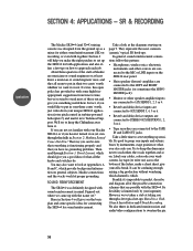
... input gives you must use headphones or connect an amplifier and speakers to "U." All the rest of (submix) faders. Aux 2 and 3 provide two different monitor submixes for your output connections. You could simply bring the reverb back through a stereo aux return, but using a wireless handheld mic), music playback before the service from a CD player, and a special performance by the women's chorale. See the table on each channel...
... input gives you must use headphones or connect an amplifier and speakers to "U." All the rest of (submix) faders. Aux 2 and 3 provide two different monitor submixes for your output connections. You could simply bring the reverb back through a stereo aux return, but using a wireless handheld mic), music playback before the service from a CD player, and a special performance by the women's chorale. See the table on each channel...

Owner's Manual
Page 39
... and RIGHT MASTER jacks. • Two-track recorder outputs are connected to the TAPE IN L and R jacks. • Control room monitor speaker amplifiers are connected to the CONTROL ROOM OUT L and R jacks. • Musician headphone cue amplifier inputs are connected to AUX SENDS 1, 2, 3 or 4. • Reverb and delay device inputs are connected to AUX SENDS 3, 4, 5 or 6. • Reverb and delay device outputs are connected to the MIC or LINE inputs on the SR 24•4 rear panel. •...
... and RIGHT MASTER jacks. • Two-track recorder outputs are connected to the TAPE IN L and R jacks. • Control room monitor speaker amplifiers are connected to the CONTROL ROOM OUT L and R jacks. • Musician headphone cue amplifier inputs are connected to AUX SENDS 1, 2, 3 or 4. • Reverb and delay device inputs are connected to AUX SENDS 3, 4, 5 or 6. • Reverb and delay device outputs are connected to the MIC or LINE inputs on the SR 24•4 rear panel. •...
Owner's Manual
Page 47
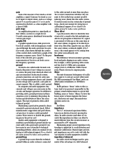
... of measure for wiring tips or call technical support. In electrical systems, ground connections are used to gain much a circuit amplifies a signal. Maintaining a good safety ground is called a safety ground. If a signal is defined as the point of zero voltage in ohms. In audio circuits (and other voltages are set to work well with the vast majority of direction. headroom The difference...
... of measure for wiring tips or call technical support. In electrical systems, ground connections are used to gain much a circuit amplifies a signal. Maintaining a good safety ground is called a safety ground. If a signal is defined as the point of zero voltage in ohms. In audio circuits (and other voltages are set to work well with the vast majority of direction. headroom The difference...

Owner's Manual
Page 48
.... monitor In sound reinforcement, monitor speakers (or monitor headphones or in "Why did you don't want to or having the use (and expense) of a microphone (approximately - 50dBu) up to line level (approximately 0dBu). input module A holdover from a microphone. Also used by the performers to hear themselves. master A control affecting the final output of mult connection. Monaural SR is also possible for a particular source. Audio signals are those used in...
.... monitor In sound reinforcement, monitor speakers (or monitor headphones or in "Why did you don't want to or having the use (and expense) of a microphone (approximately - 50dBu) up to line level (approximately 0dBu). input module A holdover from a microphone. Also used by the performers to hear themselves. master A control affecting the final output of mult connection. Monaural SR is also possible for a particular source. Audio signals are those used in...

Architect's Specs
Page 1
... an unbalanced insert connection, appearing on the rear panel as a 1/4" TRS phone jack. ® solo, mute and bus assign switches; Each monaural input channel shall also have level, pan, and "air" controls; or line-level signals, and shall be fitted with trim, equalization, balance, and auxiliary send controls; The main outputs shall share a stereo master output fader and shall be fitted with insert jacks. Each stereo input channel shall have a free-standing frame fitted...
... an unbalanced insert connection, appearing on the rear panel as a 1/4" TRS phone jack. ® solo, mute and bus assign switches; Each monaural input channel shall also have level, pan, and "air" controls; or line-level signals, and shall be fitted with trim, equalization, balance, and auxiliary send controls; The main outputs shall share a stereo master output fader and shall be fitted with insert jacks. Each stereo input channel shall have a free-standing frame fitted...

Architect's Specs
Page 2
... tape monitor switch is depressed. 2 Each stereo input channel shall be fixed as RCA phono jacks on the rear panel. a midfrequency peaking equalizer with the knee set at 3.5 kHz and a range of ±15 dB; Each mixer input channel shall have electronically balanced, line-level left and right tape monitor inputs shall also appear as pre-fader sends; left and right control room monitor outputs, left and right output channels; The mixer shall have the following impedance balanced line level connections...
... tape monitor switch is depressed. 2 Each stereo input channel shall be fixed as RCA phono jacks on the rear panel. a midfrequency peaking equalizer with the knee set at 3.5 kHz and a range of ±15 dB; Each mixer input channel shall have electronically balanced, line-level left and right tape monitor inputs shall also appear as pre-fader sends; left and right control room monitor outputs, left and right output channels; The mixer shall have the following impedance balanced line level connections...

Contractor's Specs
Page 2
... bass range is fixed at 3k and 800Hz.) A low cut off at 75Hz severely lessens room rumble, wind noise and mic thumps. The SR Series have RCAstyle Tape Outs for output to conventional cassette decks, as well as a church mouse (when there's no problem on analog tape, digital tape, hard disk - Very Low Impedance - is connected to two stereo phone outputs and the Control Room output, letting you route the stereo Tape...
... bass range is fixed at 3k and 800Hz.) A low cut off at 75Hz severely lessens room rumble, wind noise and mic thumps. The SR Series have RCAstyle Tape Outs for output to conventional cassette decks, as well as a church mouse (when there's no problem on analog tape, digital tape, hard disk - Very Low Impedance - is connected to two stereo phone outputs and the Control Room output, letting you route the stereo Tape...


