
Installation Guide
Page 1
OPT•24 Installation Guide 24-Channel 24-bit ADAT Optical I/O Card for the HDR24/96 and MDR24/96
OPT•24 Installation Guide 24-Channel 24-bit ADAT Optical I/O Card for the HDR24/96 and MDR24/96
Installation Guide
Page 2
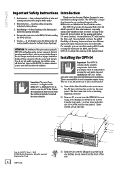
... Instructions Introduction 1. Keep these operating instructions. 4. Follow all one size. Disconnect the power source to the Mackie Service Department. The OPT•24 provides 24 channels (8x3) of 24-bit ADAT optical I /O SYNC PLAY DEC INC RECORD 3) Remove the cover by lifting it is a ...PROJECT BACKUP DISK UTIL SYSTEM FAST FWD STOP DIGI-I /O. For example, you for choosing Mackie Designs for your recorded audio. Installing the OPT•24 Important: The OPT•24 contains static-sensitive components. Use an anti-static wrist strap when performing this to be covered...
... Instructions Introduction 1. Keep these operating instructions. 4. Follow all one size. Disconnect the power source to the Mackie Service Department. The OPT•24 provides 24 channels (8x3) of 24-bit ADAT optical I /O SYNC PLAY DEC INC RECORD 3) Remove the cover by lifting it is a ...PROJECT BACKUP DISK UTIL SYSTEM FAST FWD STOP DIGI-I /O. For example, you for choosing Mackie Designs for your recorded audio. Installing the OPT•24 Important: The OPT•24 contains static-sensitive components. Use an anti-static wrist strap when performing this to be covered...
Installation Guide
Page 3
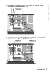
... to side to the SYNC card) by removing 1 Phillipshead screw. Installation Guide 4) Remove the blank cover plate for installing the OPT•24. 4) Remove Screw and ACC1 Slot Cover Plate RREEAARR PPAANNEELL ® MACKIE DESIGNS. ™ © 2000 ® MACKIE DESIGNS. ™ © 2000 FRONT PANEL 5) Unplug the 2 ribbon cables from the Sync card.
... to side to the SYNC card) by removing 1 Phillipshead screw. Installation Guide 4) Remove the blank cover plate for installing the OPT•24. 4) Remove Screw and ACC1 Slot Cover Plate RREEAARR PPAANNEELL ® MACKIE DESIGNS. ™ © 2000 ® MACKIE DESIGNS. ™ © 2000 FRONT PANEL 5) Unplug the 2 ribbon cables from the Sync card.
Installation Guide
Page 4
... to OPT¥24 Board OPT¥24 Board RREEAARR PPAANNEELL 4 OPT•24 FRONT PANEL Leave the cable inside the HDR24/96 in case the OPT•24 is ever removed and the COM cable needs to the edge) on the OPT•24. OPT•24 ® MACKIE DESIGNS. ™ © 2000 ® MACKIE DESIGNS.... ™ © 2000 6) Unplug both ends of the ribbon cables you removed from the edge) on the OPT•24. It doesn't matter which end of the...
... to OPT¥24 Board OPT¥24 Board RREEAARR PPAANNEELL 4 OPT•24 FRONT PANEL Leave the cable inside the HDR24/96 in case the OPT•24 is ever removed and the COM cable needs to the edge) on the OPT•24. OPT•24 ® MACKIE DESIGNS. ™ © 2000 ® MACKIE DESIGNS.... ™ © 2000 6) Unplug both ends of the ribbon cables you removed from the edge) on the OPT•24. It doesn't matter which end of the...
Installation Guide
Page 5
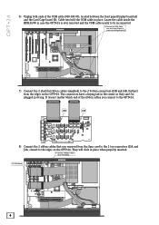
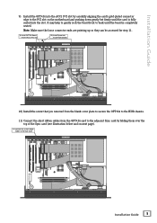
...are pointing up so they can be accessed for step 11. 9) Install OPT•24 Board into the ACC1 PCI slot 10) Install Screw into the OPT•24 bracket RREEAARR PPAANNEELL ® MACKIE DESIGNS. ™ © 2000 ® MACKIE DESIGNS. ™ © 2000 FRONT PANEL 10) Install the screw ...that you removed from the blank cover plate to secure the OPT•24 to the HDR chassis. 11) Connect...
...are pointing up so they can be accessed for step 11. 9) Install OPT•24 Board into the ACC1 PCI slot 10) Install Screw into the OPT•24 bracket RREEAARR PPAANNEELL ® MACKIE DESIGNS. ™ © 2000 ® MACKIE DESIGNS. ™ © 2000 FRONT PANEL 10) Install the screw ...that you removed from the blank cover plate to secure the OPT•24 to the HDR chassis. 11) Connect...
Installation Guide
Page 6
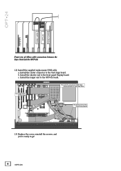
a. RREEAARR PPAANNEELL 12a) Install the replacement COM Cable: Center connector to Card Cage Board ® MACKIE DESIGNS. ™ © 2000 12c) Longer end to OPT•24 Board 12b) Shorter end to Front Panel Display Board FRONT PANEL 13) Replace the cover, reinstall the screws, and ...front panel Display board. b. Install the shorter end to go! 6 OPT•24 Install the longer end to the Card Cage board. Install the center connector to the OPT•24 board. OPT•24 SYNC CARD OPT•24 VIDEO CARD Front view of ribbon cable connections between the Sync Card ...
a. RREEAARR PPAANNEELL 12a) Install the replacement COM Cable: Center connector to Card Cage Board ® MACKIE DESIGNS. ™ © 2000 12c) Longer end to OPT•24 Board 12b) Shorter end to Front Panel Display Board FRONT PANEL 13) Replace the cover, reinstall the screws, and ...front panel Display board. b. Install the shorter end to go! 6 OPT•24 Install the longer end to the Card Cage board. Install the center connector to the OPT•24 board. OPT•24 SYNC CARD OPT•24 VIDEO CARD Front view of ribbon cable connections between the Sync Card ...
Installation Guide
Page 7
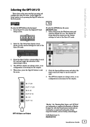
... is necessary for the outputs. 5. When done, press the Digi-I /O cards. IN 17-24 OUT 17-24 IN 9-16 OUT 9-16 IN 1-8 OUT 1-8 OPT•24 Inputs and Outputs "Mackie," the "Running Man" figure, and "OPT•24" are hereby acknowledged. © 2002 Mackie Designs Inc. The Setup Tape Inputs screen shows you the current settings for each...
... is necessary for the outputs. 5. When done, press the Digi-I /O cards. IN 17-24 OUT 17-24 IN 9-16 OUT 9-16 IN 1-8 OUT 1-8 OPT•24 Inputs and Outputs "Mackie," the "Running Man" figure, and "OPT•24" are hereby acknowledged. © 2002 Mackie Designs Inc. The Setup Tape Inputs screen shows you the current settings for each...