
Installation Guide
Page 1
OPT•24 Installation Guide 24-Channel 24-bit ADAT Optical I/O Card for the HDR24/96 and MDR24/96
OPT•24 Installation Guide 24-Channel 24-bit ADAT Optical I/O Card for the HDR24/96 and MDR24/96
Installation Guide
Page 2
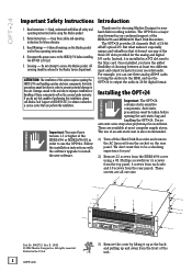
... optical I /O SYNC PLAY DEC INC RECORD 3) Remove the cover by lifting it doesn't use the OPT•24 to output the audio in a PCI slot next to be covered under warranty. Use an anti-static wrist strap when performing this installation, please call Mackie Tech Support at the back and pulling up at 800-898-3211 to obtain a referral to a service center...
... optical I /O SYNC PLAY DEC INC RECORD 3) Remove the cover by lifting it doesn't use the OPT•24 to output the audio in a PCI slot next to be covered under warranty. Use an anti-static wrist strap when performing this installation, please call Mackie Tech Support at the back and pulling up at 800-898-3211 to obtain a referral to a service center...
Installation Guide
Page 3
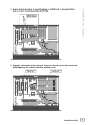
... sockets. 5A) Unplug Ribbon Cables from the Sync card. Installation Guide 4) Remove the blank cover plate for installing the OPT•24. 4) Remove Screw and ACC1 Slot Cover Plate RREEAARR PPAANNEELL ® MACKIE DESIGNS. ™ © 2000 ® MACKIE DESIGNS. ™ © 2000 FRONT PANEL 5) Unplug the 2 ribbon cables from Sync Card 5B) Pull Ribbon Cables back and out of the...
... sockets. 5A) Unplug Ribbon Cables from the Sync card. Installation Guide 4) Remove the blank cover plate for installing the OPT•24. 4) Remove Screw and ACC1 Slot Cover Plate RREEAARR PPAANNEELL ® MACKIE DESIGNS. ™ © 2000 ® MACKIE DESIGNS. ™ © 2000 FRONT PANEL 5) Unplug the 2 ribbon cables from Sync Card 5B) Pull Ribbon Cables back and out of the...
Installation Guide
Page 4
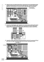
...Cable ties hold the COM cable in place when properly inserted. 8) Connect 2 Ribbon Cables to the edge) on the OPT•24. The connectors have a keying tab in wrong. OPT•24 ® MACKIE DESIGNS. ™ © 2000 ® MACKIE DESIGNS. ™ © 2000 6) Unplug both ends of the ribbon cables...and J4B, furthest from the Sync card to the 2 top connectors (J3A and J4A, closest to OPT¥24 Board OPT¥24 Board RREEAARR PPAANNEELL 4 OPT•24 FRONT PANEL J3B J4B 8) Connect the 2 ribbon cables that you connect to be plugged in the center so they can't be ...
...Cable ties hold the COM cable in place when properly inserted. 8) Connect 2 Ribbon Cables to the edge) on the OPT•24. The connectors have a keying tab in wrong. OPT•24 ® MACKIE DESIGNS. ™ © 2000 ® MACKIE DESIGNS. ™ © 2000 6) Unplug both ends of the ribbon cables...and J4B, furthest from the Sync card to the 2 top connectors (J3A and J4A, closest to OPT¥24 Board OPT¥24 Board RREEAARR PPAANNEELL 4 OPT•24 FRONT PANEL J3B J4B 8) Connect the 2 ribbon cables that you connect to be plugged in the center so they can't be ...
Installation Guide
Page 5
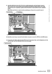
... MACKIE DESIGNS. ™ © 2000 ® MACKIE DESIGNS. ™ © 2000 FRONT PANEL 10) Install the screw that you removed from the blank cover plate to secure the OPT•24 to the HDR chassis. 11) Connect the short ribbon cables from the OPT•24 card to the adjacent Sync ...connector edge to the PCI slot on next page). 11) Connect the 2 short ribbon cables to back until the board is completely seated. It may help to gently rock the board front to the Sync Card RREEAARR PPAANNEELL FRONT PANEL Installation Guide 5 Note: Make sure the loose connector ends are pointing up...
... MACKIE DESIGNS. ™ © 2000 ® MACKIE DESIGNS. ™ © 2000 FRONT PANEL 10) Install the screw that you removed from the blank cover plate to secure the OPT•24 to the HDR chassis. 11) Connect the short ribbon cables from the OPT•24 card to the adjacent Sync ...connector edge to the PCI slot on next page). 11) Connect the 2 short ribbon cables to back until the board is completely seated. It may help to gently rock the board front to the Sync Card RREEAARR PPAANNEELL FRONT PANEL Installation Guide 5 Note: Make sure the loose connector ends are pointing up...
Installation Guide
Page 6
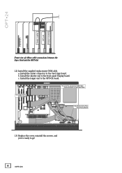
...;24 SYNC CARD OPT•24 VIDEO CARD Front view of ribbon cable connections between the Sync Card and the OPT•24 12) Install the supplied replacement COM cable. Install the shorter end to the OPT•24 board. Install the longer end to the front panel Display board. a. RREEAARR PPAANNEELL 12a) Install the replacement COM Cable: Center connector to Card Cage Board ® MACKIE DESIGNS...
...;24 SYNC CARD OPT•24 VIDEO CARD Front view of ribbon cable connections between the Sync Card and the OPT•24 12) Install the supplied replacement COM cable. Install the shorter end to the OPT•24 board. Install the longer end to the front panel Display board. a. RREEAARR PPAANNEELL 12a) Install the replacement COM Cable: Center connector to Card Cage Board ® MACKIE DESIGNS...
Installation Guide
Page 7
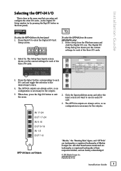
... Outputs "Mackie," the "Running Man" figure, and "OPT•24" are always active, so no configuration is necessary for the outputs. 5. All other I/O cards-in the Digital I/O Setup window (or by pressing the Digi-I/O button on the front panel). Press the Select button corresponding to each I/O card and toggle the selection to enter the Digital I/O Card Setup screen. Click the Input pulldown menu and select the input source...
... Outputs "Mackie," the "Running Man" figure, and "OPT•24" are always active, so no configuration is necessary for the outputs. 5. All other I/O cards-in the Digital I/O Setup window (or by pressing the Digi-I/O button on the front panel). Press the Select button corresponding to each I/O card and toggle the selection to enter the Digital I/O Card Setup screen. Click the Input pulldown menu and select the input source...


