

Owners Manual
Page 4
...Section ...24 Remote CPU Description...25 Data and Synchronization I/O ...25 Connecting a Mouse, Keyboard and SVGA Monitor 25 Other Connections ...25 Control Surface Functions ...26 Channel Strip Section ...26 Master Section Description ...28 Master Fader/Bank Select Section ...28 Master V-Pot Section ...29 ...V-Pot Assign Section ...30 Figure 2-1 Aux Sends 1-8 (Default - Mackie Stereo Effects [4 MFX Cards 31 Fat Channel Section...32 Studio/Solo Section ...33 Phones/Cue Mix Section ...34 D8B Manual • Table of These Concepts ...12 Figure 1-5 Signal-Flow Diagram ...13 Figure...
...Section ...24 Remote CPU Description...25 Data and Synchronization I/O ...25 Connecting a Mouse, Keyboard and SVGA Monitor 25 Other Connections ...25 Control Surface Functions ...26 Channel Strip Section ...26 Master Section Description ...28 Master Fader/Bank Select Section ...28 Master V-Pot Section ...29 ...V-Pot Assign Section ...30 Figure 2-1 Aux Sends 1-8 (Default - Mackie Stereo Effects [4 MFX Cards 31 Fat Channel Section...32 Studio/Solo Section ...33 Phones/Cue Mix Section ...34 D8B Manual • Table of These Concepts ...12 Figure 1-5 Signal-Flow Diagram ...13 Figure...
Owners Manual
Page 5
Control Room Section ...34 Clipboard Section ...35 Master L-R/Shortcuts Section ...36 Bus Assignment Section...36 Automation Section ...36 Session Setup Section ...38 Transport Section ...39 Chapter 3: ...+9) ...90 Track Sheet (Ctrl+T) ...92 The History List Window (Ctrl+H)...92 The MIDI Map Window (Ctrl + -) ...93 Erase UFX Memory...94 Upgrade UFX Cards...94 D8B Manual • Table of Contents • page ii
Control Room Section ...34 Clipboard Section ...35 Master L-R/Shortcuts Section ...36 Bus Assignment Section...36 Automation Section ...36 Session Setup Section ...38 Transport Section ...39 Chapter 3: ...+9) ...90 Track Sheet (Ctrl+T) ...92 The History List Window (Ctrl+H)...92 The MIDI Map Window (Ctrl + -) ...93 Erase UFX Memory...94 Upgrade UFX Cards...94 D8B Manual • Table of Contents • page ii
Owners Manual
Page 7
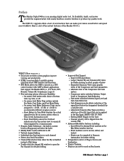
...four EQ types that can be used on -screen Help to quickly answer questions about D8B features and functions • HUI Mode allows the D8B to operate as a HUI control surface with DAW software applications that support the Mackie HUI (i.e., Pro Tools, DP3, Nuendo, Cubase SX, Soundscape, Logic 6) •... NEW WITH v5.1 • Great new overview screen graphics improve viewing and productivity • HTML on Bus Inserts D8B Manual • Preface • page 1 Preface The Mackie Digital 8•Bus is disabled instead of flat-lining • Double-click the channel EQ window to open the ...
...four EQ types that can be used on -screen Help to quickly answer questions about D8B features and functions • HUI Mode allows the D8B to operate as a HUI control surface with DAW software applications that support the Mackie HUI (i.e., Pro Tools, DP3, Nuendo, Cubase SX, Soundscape, Logic 6) •... NEW WITH v5.1 • Great new overview screen graphics improve viewing and productivity • HTML on Bus Inserts D8B Manual • Preface • page 1 Preface The Mackie Digital 8•Bus is disabled instead of flat-lining • Double-click the channel EQ window to open the ...

Owners Manual
Page 8
...session information with the session itself • Track Sheet can be exported as an HTML file or text file • Channel Notes window for v5.1. D8B Manual • Preface • page 2 Alternately, there is an option to double-check your EQ settings and make sure they are updating from ...the Surround window ° Surround panning appears in Fat Channel • Adjustable attenuation for the Control Room DIM switch includes -20 dB, -30 dB, -40 dB, and off • Track Sheet stores all the parameters on the selected channel ...
...session information with the session itself • Track Sheet can be exported as an HTML file or text file • Channel Notes window for v5.1. D8B Manual • Preface • page 2 Alternately, there is an option to double-check your EQ settings and make sure they are updating from ...the Surround window ° Surround panning appears in Fat Channel • Adjustable attenuation for the Control Room DIM switch includes -20 dB, -30 dB, -40 dB, and off • Track Sheet stores all the parameters on the selected channel ...
Owners Manual
Page 10
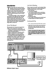
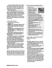
About This Manual This manual is snug and finger-tight. We assume you design the perfect system for your needs-all surface controls. • Chapter 3 describes the on achieving successful routing of an audio source to your investment remains current for many years ... • MADE IN USA • FABRIQUE AU USA • COPYRIGHT ©1997 • THE FOLLOWING ARE TRADEMARKS OR REGISTERED TRADEMARKS OF MACKIE DESIGN INC.: "MACKIE", "DIGITAL SYSTEMS", D8B AND THE "RUNNING MAN" FIGURE • AUX 3 LINE IN LINE IN INSERT INSERT AUX 2 AUX 1 PATENTS PENDING DC Power Cable Data...
About This Manual This manual is snug and finger-tight. We assume you design the perfect system for your needs-all surface controls. • Chapter 3 describes the on achieving successful routing of an audio source to your investment remains current for many years ... • MADE IN USA • FABRIQUE AU USA • COPYRIGHT ©1997 • THE FOLLOWING ARE TRADEMARKS OR REGISTERED TRADEMARKS OF MACKIE DESIGN INC.: "MACKIE", "DIGITAL SYSTEMS", D8B AND THE "RUNNING MAN" FIGURE • AUX 3 LINE IN LINE IN INSERT INSERT AUX 2 AUX 1 PATENTS PENDING DC Power Cable Data...

Owners Manual
Page 13
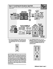
...L/R fader, locate four buttons labeled MIC/LINE, TAPE IN, EFFECTS, and MASTERS. Use of a computer monitor provides onscreen control of two fader banks at first glance. MIDI 1-8; Switch D8B power on monitor amplifier or powered monitors. FAST TRACK 4. With the Digital 8•Bus, what you get is ready to..., recorders, interfaces, etc.). Turn on the power switch on the front panel of the Remote CPU, then turn on the power to load the Mackie Real Time OS (Operating System) and initialize the DSPs. The Digital 8•Bus takes a few moments to all the way down. 3. Verify that...
...L/R fader, locate four buttons labeled MIC/LINE, TAPE IN, EFFECTS, and MASTERS. Use of a computer monitor provides onscreen control of two fader banks at first glance. MIDI 1-8; Switch D8B power on monitor amplifier or powered monitors. FAST TRACK 4. With the Digital 8•Bus, what you get is ready to..., recorders, interfaces, etc.). Turn on the power switch on the front panel of the Remote CPU, then turn on the power to load the Mackie Real Time OS (Operating System) and initialize the DSPs. The Digital 8•Bus takes a few moments to all the way down. 3. Verify that...
Owners Manual
Page 14
...primary applications the Digital 8•Bus was designed for each bank. however, at the same time providing tons of control through automation, routing, and DSP! D8B Manual • Chapter 1 • page 8 leave it 's possible to route channels to their respective settings ...3 (Channels 49- 72: Internal Effects Returns, FX 1-16, and ALT RETurns 1-8) • MASTERS button = Fader Bank 4 (Virtual Groups 1-8, MIDI Controllers 1-8, Bus Masters 1-8) • SHIFT+MASTERS button = Fader Bank 5 (with . The layered approach to crystal-clear audio. This setup provides an amazing ...
...primary applications the Digital 8•Bus was designed for each bank. however, at the same time providing tons of control through automation, routing, and DSP! D8B Manual • Chapter 1 • page 8 leave it 's possible to route channels to their respective settings ...3 (Channels 49- 72: Internal Effects Returns, FX 1-16, and ALT RETurns 1-8) • MASTERS button = Fader Bank 4 (Virtual Groups 1-8, MIDI Controllers 1-8, Bus Masters 1-8) • SHIFT+MASTERS button = Fader Bank 5 (with . The layered approach to crystal-clear audio. This setup provides an amazing ...
Owners Manual
Page 15
...-release tape across the top label strip allows for storage with gain TRIM down. CONTROL ROOM 2 TRACK A DIGITAL IN 1 2 TRACK B DIGITAL IN 2 2 TRACK C MASTER L-R MONO OR NEAR FIELD MAIN SPEAKERS SPEAKER LEVEL DIM TALKBACK D8B Manual • Chapter 1 • page 9 Figure 1-1 Completing the Microphone Signal... guaranteeing accurate settings whenever you need to Hear 5. This kind of tape can be removed and folded for careful recording of the only controls that are necessary. TRIM LINE MIC 0 60 -20dB +40dB 1 MIC Note: The TRIM and MIC button status are two of each...
...-release tape across the top label strip allows for storage with gain TRIM down. CONTROL ROOM 2 TRACK A DIGITAL IN 1 2 TRACK B DIGITAL IN 2 2 TRACK C MASTER L-R MONO OR NEAR FIELD MAIN SPEAKERS SPEAKER LEVEL DIM TALKBACK D8B Manual • Chapter 1 • page 9 Figure 1-1 Completing the Microphone Signal... guaranteeing accurate settings whenever you need to Hear 5. This kind of tape can be removed and folded for careful recording of the only controls that are necessary. TRIM LINE MIC 0 60 -20dB +40dB 1 MIC Note: The TRIM and MIC button status are two of each...

Owners Manual
Page 17
... monitor the mix from the TAPE IN Fader Bank throughout tracking. Once levels to tape are set, using the Channel Trim controls, it's typically best to L/R Mix D8B Manual • Chapter 1 • page 11 FAST TRACK Channel 1-24 Mic/Line In Monitor Outs to Speakers Channels ... Bank 1 Figure 1-3 Setting Up to Track The graphic below highlights the simplicity of the D8B. Figure 1-2 Simple Microphone Connection/Basic Live Setup This setup illustrates the most fundamental use of the D8B tracking procedure. A very basic live setting might require only this limited level of complexity.
... monitor the mix from the TAPE IN Fader Bank throughout tracking. Once levels to tape are set, using the Channel Trim controls, it's typically best to L/R Mix D8B Manual • Chapter 1 • page 11 FAST TRACK Channel 1-24 Mic/Line In Monitor Outs to Speakers Channels ... Bank 1 Figure 1-3 Setting Up to Track The graphic below highlights the simplicity of the D8B. Figure 1-2 Simple Microphone Connection/Basic Live Setup This setup illustrates the most fundamental use of the D8B tracking procedure. A very basic live setting might require only this limited level of complexity.
Owners Manual
Page 18
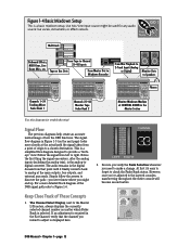
... to the layered consoles, maneuvering throughout the entire console will become second nature. At first it finally converts back to analog at CONTROL ROOM in Figure 1-5 (on the next page) looks more detailed block diagram of origin to a chosen destination. Keep Close Track of how...that the channel you might be used for troubleshooting! MASTERS 1-24 SHIFT 25-48 MIC/LINE (TRACK) TAPE IN (MONITOR) 49-72 EFFECTS BANK SELECT D8B Manual • Chapter 1 • page 12 Figure 1-4 Basic Mixdown Setup This is a simplified flow-diagram designed to provide a "bird'seye" view....
... to the layered consoles, maneuvering throughout the entire console will become second nature. At first it finally converts back to analog at CONTROL ROOM in Figure 1-5 (on the next page) looks more detailed block diagram of origin to a chosen destination. Keep Close Track of how...that the channel you might be used for troubleshooting! MASTERS 1-24 SHIFT 25-48 MIC/LINE (TRACK) TAPE IN (MONITOR) 49-72 EFFECTS BANK SELECT D8B Manual • Chapter 1 • page 12 Figure 1-4 Basic Mixdown Setup This is a simplified flow-diagram designed to provide a "bird'seye" view....

Owners Manual
Page 19
...check the status of the V-Pot before making a change you want when it 's assigned to reach the master output. Since the V-Pot is a multifunction control, it's easy to Analog Converter Aux Sends Lake Sammamish 6 miles CR Nearfield Out CR Main Out Studio Out Phones 1 Out Phones 2 Out 3. AUX 9-...PAN AUX 11-12 PAN MASTER PAN SOLO 1-24 LEVEL TO TAPE 1-48 DIGITAL TRIM AUX 1 AUX 2 AUX 3 AUX 4 AUX 5 AUX 6 AUX 7 AUX 8 D8B Manual • Chapter 1 • page 13 Tracking/Routing Channel Meter Analog Inputs CH 1-24 Pre-DSP Insert Post-DSP Insert Analog to Digital Converter DSP...
...check the status of the V-Pot before making a change you want when it 's assigned to reach the master output. Since the V-Pot is a multifunction control, it's easy to Analog Converter Aux Sends Lake Sammamish 6 miles CR Nearfield Out CR Main Out Studio Out Phones 1 Out Phones 2 Out 3. AUX 9-...PAN AUX 11-12 PAN MASTER PAN SOLO 1-24 LEVEL TO TAPE 1-48 DIGITAL TRIM AUX 1 AUX 2 AUX 3 AUX 4 AUX 5 AUX 6 AUX 7 AUX 8 D8B Manual • Chapter 1 • page 13 Tracking/Routing Channel Meter Analog Inputs CH 1-24 Pre-DSP Insert Post-DSP Insert Analog to Digital Converter DSP...

Owners Manual
Page 20
B, C, D cards) ALT I/O CARD 65-72 (optional) A to D Analog 8 channel TAPE CARD (optional) FX card A. D8B Manual • Chapter 1 • page 14 CHANNEL TAP ALT RETURNS 2-TRACK DIGITAL BUS TAP/AUX TAP ANALOG STEREO INSERT/RETURN MIC/LINE 1 (through 12) MIC ... 40) A to D Analog 8 channel TAPE CARD (optional) FROM TAPE 41 (through 48) A to D TDIF/ADAT 8 channel format (optional) AES/EBU & S/PDIF STEREO INPUT TO CONTROL ROOM SELECT "Mackie Digital 8•Bus Block Diagram 2 / 28 / 2003" METER DIRECT ASSIGN TO TAPE OUT PFL SOLO MUTE PAN FADER PRE/ POST AUX 1-8 AUX LEVEL AUX...
B, C, D cards) ALT I/O CARD 65-72 (optional) A to D Analog 8 channel TAPE CARD (optional) FX card A. D8B Manual • Chapter 1 • page 14 CHANNEL TAP ALT RETURNS 2-TRACK DIGITAL BUS TAP/AUX TAP ANALOG STEREO INSERT/RETURN MIC/LINE 1 (through 12) MIC ... 40) A to D Analog 8 channel TAPE CARD (optional) FROM TAPE 41 (through 48) A to D TDIF/ADAT 8 channel format (optional) AES/EBU & S/PDIF STEREO INPUT TO CONTROL ROOM SELECT "Mackie Digital 8•Bus Block Diagram 2 / 28 / 2003" METER DIRECT ASSIGN TO TAPE OUT PFL SOLO MUTE PAN FADER PRE/ POST AUX 1-8 AUX LEVEL AUX...

Owners Manual
Page 21
... CHANNELS TO MAIN L/R BUS MAIN INSERT R (L) MASTER FADER MIXDOWN PFL SOLO PFL/AFL/MIXDOWN AFL SOLO LEVEL AUX SOLO 9 (10) D / A D / A D8B OUTPUT SECTION X2 LEFT AND (RIGHT) AUX 9/10 MASTER AUX SOLO 11 (12) AUX 11/12 MASTER D / A D / A D / A TO SOLO BUS...TRK IN A B C D / A TALKBACK (R) TALKBACK TO STUDIO DIG IN 1 DIG IN 2 MASTER L-R 2 TRK A 2 TRK B 2 TRK C CONTROL ROOM SELECT METERS LEVEL NEARFIELD DIM D / A BUS BUS INSERTS TAP SOLO CONTROL SURROUND MONITOR LEVELS (x8 + MASTER) BUS LEVEL LEVEL TO TAPE MUTE ASSIGN LEVEL MONO LEFT (R) DIM MAIN LEVEL D / A LEVEL TO...
... CHANNELS TO MAIN L/R BUS MAIN INSERT R (L) MASTER FADER MIXDOWN PFL SOLO PFL/AFL/MIXDOWN AFL SOLO LEVEL AUX SOLO 9 (10) D / A D / A D8B OUTPUT SECTION X2 LEFT AND (RIGHT) AUX 9/10 MASTER AUX SOLO 11 (12) AUX 11/12 MASTER D / A D / A D / A TO SOLO BUS...TRK IN A B C D / A TALKBACK (R) TALKBACK TO STUDIO DIG IN 1 DIG IN 2 MASTER L-R 2 TRK A 2 TRK B 2 TRK C CONTROL ROOM SELECT METERS LEVEL NEARFIELD DIM D / A BUS BUS INSERTS TAP SOLO CONTROL SURROUND MONITOR LEVELS (x8 + MASTER) BUS LEVEL LEVEL TO TAPE MUTE ASSIGN LEVEL MONO LEFT (R) DIM MAIN LEVEL D / A LEVEL TO...

Owners Manual
Page 22
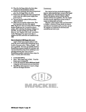
... up +10 dB 0 0 0 Main L-R XLR +28 dBu max out TRS +22 dBu max out level up +10 dB 0 0 ch aux level 0 0 st. Figure 1-7 D8B Gain Structure Diagram D8B Manual • Chapter 1 • page 16 line in 1-12 +22 dBu max input 20 dB loss +2 dBu max input 0 mic in 1-12 40 dB... 0 digital trim compressor gain dn -15 dB pan cntr -3 dB 4 band EQ channel fader pan Mackie Effects gain up +12 dB 0 gain dn -12 dB EQ Aux send +22 dBu max out level up +10 0 0 0 Control Room +22 dBu max out 0 Max Level @ Unity gain 20 dB gain Inputs 25-48, Returns...
... up +10 dB 0 0 0 Main L-R XLR +28 dBu max out TRS +22 dBu max out level up +10 dB 0 0 ch aux level 0 0 st. Figure 1-7 D8B Gain Structure Diagram D8B Manual • Chapter 1 • page 16 line in 1-12 +22 dBu max input 20 dB loss +2 dBu max input 0 mic in 1-12 40 dB... 0 digital trim compressor gain dn -15 dB pan cntr -3 dB 4 band EQ channel fader pan Mackie Effects gain up +12 dB 0 gain dn -12 dB EQ Aux send +22 dBu max out level up +10 0 0 0 Control Room +22 dBu max out 0 Max Level @ Unity gain 20 dB gain Inputs 25-48, Returns...
Owners Manual
Page 25
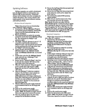
...the provided text box and then press the Unzip button. d8b5xxxx Install 3.img). 8. Power on the D8B control surface. (Note: The installer no longer uses the VGA screen; Power on the D8B control surface. (Note: The installer no longer uses the VGA screen; typical boot is about 30 seconds...We recommend that the "Writing On Floppy" check box is set to download the DiskCopy utility from the computer, be downloaded from the Mackie website at www.mackie.com. Ensure that you may need to C:\. Repeat steps 5 through 6 to extract the three disk images. 3. Remove the 3rd floppy...
...the provided text box and then press the Unzip button. d8b5xxxx Install 3.img). 8. Power on the D8B control surface. (Note: The installer no longer uses the VGA screen; Power on the D8B control surface. (Note: The installer no longer uses the VGA screen; typical boot is about 30 seconds...We recommend that the "Writing On Floppy" check box is set to download the DiskCopy utility from the computer, be downloaded from the Mackie website at www.mackie.com. Ensure that you may need to C:\. Repeat steps 5 through 6 to extract the three disk images. 3. Remove the 3rd floppy...
Owners Manual
Page 26
...Memory" and "Upgrade UFX Cards" procedures (under Windows in the upper menu bar) to upgrade the UFX cards that are installed in the D8B. Once you have important info about this upgrade. from http://www.aladdinsys.com/ shrinkwrap/index.html. Remove the 2nd floppy disk when prompted ...for steps 3-6 in update. Locate the image file labeled d8b5xxxx Install 1.img that you . The following two chapters describe the physical surface controls and the software features and capabilities. Remove the 3rd floppy disk when prompted and power down the console power supply, then power back on ...
...Memory" and "Upgrade UFX Cards" procedures (under Windows in the upper menu bar) to upgrade the UFX cards that are installed in the D8B. Once you have important info about this upgrade. from http://www.aladdinsys.com/ shrinkwrap/index.html. Remove the 2nd floppy disk when prompted ...for steps 3-6 in update. Locate the image file labeled d8b5xxxx Install 1.img that you . The following two chapters describe the physical surface controls and the software features and capabilities. Remove the 3rd floppy disk when prompted and power down the console power supply, then power back on ...

Owners Manual
Page 28
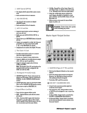
... On/Off button depending on the control surface channel strip. • 1/4" TRS channel insert/direct output jack. Rear Panel Description This section describes rear panel connector types, their functions, and associated signal buses. Each slot provides I /O cards of the D8B. Depending on the specific I /O... . Each I/O card contains its own labeling protocol, but the fundamental concepts described above pertain to work efficiently. The D8B can put them to all the controls so you can be routed out the tape outputs. • FROM TAPE (INPUT) - It's amazing how artistically...
... On/Off button depending on the control surface channel strip. • 1/4" TRS channel insert/direct output jack. Rear Panel Description This section describes rear panel connector types, their functions, and associated signal buses. Each slot provides I /O cards of the D8B. Depending on the specific I /O... . Each I/O card contains its own labeling protocol, but the fundamental concepts described above pertain to work efficiently. The D8B can put them to all the controls so you can be routed out the tape outputs. • FROM TAPE (INPUT) - It's amazing how artistically...
Owners Manual
Page 29
...slave clock source. • Supports 48kHz and 44.1kHz internal sample rates, with the D8B. 7 The Digital I/O Card (2-track) • AES/EBU digital I/O. Input is connected to DIGITAL 2 in the CONTROL ROOM monitor section. • Same source output as MASTER L-R. 8 Digital Effects Card ... with vari-speed capabilities. • Supports external sample rates between 32kHz and 50kHz. D8B Manual • Chapter 2 • page 23 Stereo interconnect for channels 1-48 (Pre- Mackie Effects card with functions dependent on the console surface. • Both sets deliver balanced...
...slave clock source. • Supports 48kHz and 44.1kHz internal sample rates, with the D8B. 7 The Digital I/O Card (2-track) • AES/EBU digital I/O. Input is connected to DIGITAL 2 in the CONTROL ROOM monitor section. • Same source output as MASTER L-R. 8 Digital Effects Card ... with vari-speed capabilities. • Supports external sample rates between 32kHz and 50kHz. D8B Manual • Chapter 2 • page 23 Stereo interconnect for channels 1-48 (Pre- Mackie Effects card with functions dependent on the console surface. • Both sets deliver balanced...

Owners Manual
Page 30
... linked together. • Post-DSP, Master L/R fader, and D/A converter. • The signal fed to these outputs is selected in the control room monitoring section. • Can accept balanced and unbalanced signals. D8B Manual • Chapter 2 • page 24 br 2 TRACK A, B, and C • Balanced 1/4" TRS inputs for headphones with exceptionally high or low...
... linked together. • Post-DSP, Master L/R fader, and D/A converter. • The signal fed to these outputs is selected in the control room monitoring section. • Can accept balanced and unbalanced signals. D8B Manual • Chapter 2 • page 24 br 2 TRACK A, B, and C • Balanced 1/4" TRS inputs for headphones with exceptionally high or low...
Owners Manual
Page 31
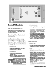
... • COPYRIGHT ©1997 • THE FOLLOWING ARE TRADEMARKS OR REGISTERED TRADEMARKS OF MACKIE DESIGN INC.: "MACKIE", "DIGITAL SYSTEMS", D8B AND THE "RUNNING MAN" FIGURE • Remote CPU Description Data and Synchronization I /O connection. • MIDI IN receives MTC, program changes, and controller, note, and poly aftertouch messages. • MIDI OUT sends MMC commands, program...
... • COPYRIGHT ©1997 • THE FOLLOWING ARE TRADEMARKS OR REGISTERED TRADEMARKS OF MACKIE DESIGN INC.: "MACKIE", "DIGITAL SYSTEMS", D8B AND THE "RUNNING MAN" FIGURE • Remote CPU Description Data and Synchronization I /O connection. • MIDI IN receives MTC, program changes, and controller, note, and poly aftertouch messages. • MIDI OUT sends MMC commands, program...

