
Owner's Manual
Page 2
...for radio noise emissions from the AC mains service when the power switch is in excess of producing high sound pressure levels use this Mackie product. 11. This Mackie product should be taken so that all persons exposed to equipment capable of these operating instructions ...use hearing protectors while the equipment is in installation such as set forth here. or D. This Mackie product has been dropped, or its proper ventilation. Unplug this Mackie product is not completely disconnected from digital apparatus as a bookcase or cabinet that they exit this polarized plug...
...for radio noise emissions from the AC mains service when the power switch is in excess of producing high sound pressure levels use this Mackie product. 11. This Mackie product should be taken so that all persons exposed to equipment capable of these operating instructions ...use hearing protectors while the equipment is in installation such as set forth here. or D. This Mackie product has been dropped, or its proper ventilation. Unplug this Mackie product is not completely disconnected from digital apparatus as a bookcase or cabinet that they exit this polarized plug...
Owner's Manual
Page 4
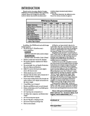
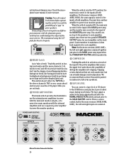
..., and the rest of the manual explains the wealth of ordinary mixers or amplifiers. Reliability is playing • Power amp routing switch selects main out only or main on one output and monitor on the other output • 3-band EQ on each channel • Monitor and Effects send on each channel • Balanced/unbalanced 1/4" and XLR inputs on each channel • 1/4" Insert jacks on page 6. That's why...
..., and the rest of the manual explains the wealth of ordinary mixers or amplifiers. Reliability is playing • Power amp routing switch selects main out only or main on one output and monitor on the other output • 3-band EQ on each channel • Monitor and Effects send on each channel • Balanced/unbalanced 1/4" and XLR inputs on each channel • 1/4" Insert jacks on page 6. That's why...
Owner's Manual
Page 5
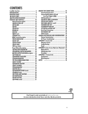
... Connecting Microphones and Line-Level Signals 21 Channel Inserts 22 EFFECTS SEND and RETURN 23 EFX FOOT SWITCH 23 POWER AMP IN 1 and 2 23 MIXER LINE OUT 24 MONITOR LINE OUT 24 TAPE IN and TAPE OUT 24 Rear Panel Connections 25 SPEAKER OUT 25 IEC Socket 25 GENERAL PRECAUTIONS AND CONSIDERATIONS . 26 Thermal Considerations 26 AC Power Considerations 26 APPENDIX A: Service Info 27 Warranty Service 27 Troubleshooting 27 Repair...
... Connecting Microphones and Line-Level Signals 21 Channel Inserts 22 EFFECTS SEND and RETURN 23 EFX FOOT SWITCH 23 POWER AMP IN 1 and 2 23 MIXER LINE OUT 24 MONITOR LINE OUT 24 TAPE IN and TAPE OUT 24 Rear Panel Connections 25 SPEAKER OUT 25 IEC Socket 25 GENERAL PRECAUTIONS AND CONSIDERATIONS . 26 Thermal Considerations 26 AC Power Considerations 26 APPENDIX A: Service Info 27 Warranty Service 27 Troubleshooting 27 Repair...
Owner's Manual
Page 6
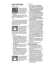
... player or tape recorder output. Turn on the POWER switch, which means the heatsink on the rear panel. 5. Turn up the INPUT LEVEL SET control until you can connect any connections. 2. When powering up . • When you might have to pay for ventilation. Connections 1. Plug a balanced microphone into one of plug supplied with 1/4" TS plugs. Plug the speakers (2 ohms or greater) into anything except speakers (unless you plug two speakers into a 3-prong AC outlet properly configured for speaker cables! Set all...
... player or tape recorder output. Turn on the POWER switch, which means the heatsink on the rear panel. 5. Turn up the INPUT LEVEL SET control until you can connect any connections. 2. When powering up . • When you might have to pay for ventilation. Connections 1. Plug a balanced microphone into one of plug supplied with 1/4" TS plugs. Plug the speakers (2 ohms or greater) into anything except speakers (unless you plug two speakers into a 3-prong AC outlet properly configured for speaker cables! Set all...
Owner's Manual
Page 7
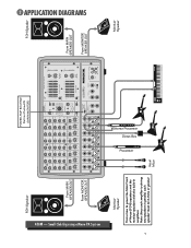
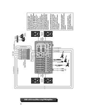
... VOLUME CH. Vocal Mics Monitor Speaker ROOM EFX WIDE DELAY 1 DELAY 2 DELAY 3 DELAY 4 CHORUS FLANGE PHASER SPRING LOW 80Hz PARAMETERS NORMAL NORMAL NORMAL INPUT LEVEL SET NORMAL INPUT LEVEL SET NORMAL INPUT LEVEL SET NORMAL INPUT LEVEL SET NORMAL INPUT LEVEL SET NORMAL INPUT LEVEL SET NORMAL INPUT LEVEL SET NORMAL INPUT LEVEL SET LOW HI U LOW HI U LOW HI U LOW HI U LOW HI U LOW HI U LOW HI U LOW HI U 0 10 TIME RATE REVERBS DELAYS CHORUS FLANGE PHASER 0 10 DAMPING DEPTH OO +20dB 1 VOLUME CH. OO +20dB 5 VOLUME CH. APPLICATION DIAGRAMS Stereo Processor Direct...
... VOLUME CH. Vocal Mics Monitor Speaker ROOM EFX WIDE DELAY 1 DELAY 2 DELAY 3 DELAY 4 CHORUS FLANGE PHASER SPRING LOW 80Hz PARAMETERS NORMAL NORMAL NORMAL INPUT LEVEL SET NORMAL INPUT LEVEL SET NORMAL INPUT LEVEL SET NORMAL INPUT LEVEL SET NORMAL INPUT LEVEL SET NORMAL INPUT LEVEL SET NORMAL INPUT LEVEL SET NORMAL INPUT LEVEL SET LOW HI U LOW HI U LOW HI U LOW HI U LOW HI U LOW HI U LOW HI U LOW HI U 0 10 TIME RATE REVERBS DELAYS CHORUS FLANGE PHASER 0 10 DAMPING DEPTH OO +20dB 1 VOLUME CH. OO +20dB 5 VOLUME CH. APPLICATION DIAGRAMS Stereo Processor Direct...
Owner's Manual
Page 8
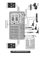
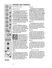
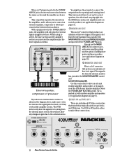
...Mics From MONITOR LINE OUT Monitor Amplifier Monitor Speakers Left FOH Speaker POWER AMP ROUTING Button OUT Right FOH Speaker Stereo Processor Direct Box Processor 408S - ROOM EFX BYPASS EFX WIDE DELAY 1 DELAY 2 DELAY 3 DELAY 4 CHORUS FLANGE PHASER SPRING PARAMETERS PAN NORMAL NORMAL L R NORMAL INPUT LEVEL SET L R NORMAL INPUT LEVEL SET L R NORMAL INPUT LEVEL SET L R NORMAL INPUT LEVEL SET L R NORMAL INPUT LEVEL SET L R NORMAL INPUT LEVEL SET L R NORMAL INPUT LEVEL SET L R NORMAL INPUT LEVEL SET LOW HI U LOW HI U LOW HI U LOW HI U LOW HI U LOW...
...Mics From MONITOR LINE OUT Monitor Amplifier Monitor Speakers Left FOH Speaker POWER AMP ROUTING Button OUT Right FOH Speaker Stereo Processor Direct Box Processor 408S - ROOM EFX BYPASS EFX WIDE DELAY 1 DELAY 2 DELAY 3 DELAY 4 CHORUS FLANGE PHASER SPRING PARAMETERS PAN NORMAL NORMAL L R NORMAL INPUT LEVEL SET L R NORMAL INPUT LEVEL SET L R NORMAL INPUT LEVEL SET L R NORMAL INPUT LEVEL SET L R NORMAL INPUT LEVEL SET L R NORMAL INPUT LEVEL SET L R NORMAL INPUT LEVEL SET L R NORMAL INPUT LEVEL SET LOW HI U LOW HI U LOW HI U LOW HI U LOW HI U LOW...
Owner's Manual
Page 9
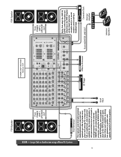
... INPUT LEVEL SET NORMAL INPUT LEVEL SET NORMAL INPUT LEVEL SET LOW HI U LOW HI U LOW HI U LOW HI U LOW HI U LOW HI U LOW HI U LOW HI U 0 10 TIME RATE REVERBS DELAYS CHORUS FLANGE PHASER 0 10 DAMPING DEPTH OO +20dB 1 VOLUME CH. OO +20dB 2 VOLUME CH. OO +20dB 5 VOLUME CH. CD Player Effects Processor From MONITOR LINE OUT Cassette Deck Monitor Amplifier Vocal Mics Monitor Speakers Note: Since each speaker must be 4 ohms or greater. OO +20dB 6 VOLUME CH. Large Club or Auditorium using...
... INPUT LEVEL SET NORMAL INPUT LEVEL SET NORMAL INPUT LEVEL SET LOW HI U LOW HI U LOW HI U LOW HI U LOW HI U LOW HI U LOW HI U LOW HI U 0 10 TIME RATE REVERBS DELAYS CHORUS FLANGE PHASER 0 10 DAMPING DEPTH OO +20dB 1 VOLUME CH. OO +20dB 2 VOLUME CH. OO +20dB 5 VOLUME CH. CD Player Effects Processor From MONITOR LINE OUT Cassette Deck Monitor Amplifier Vocal Mics Monitor Speakers Note: Since each speaker must be 4 ohms or greater. OO +20dB 6 VOLUME CH. Large Club or Auditorium using...
Owner's Manual
Page 11
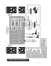
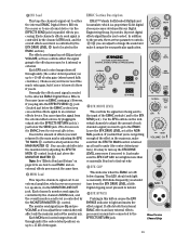
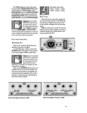
... STEREO PROFESSIONAL POWERED MIXER L POWER AMP IN MAINS R POWER AMP IN MONITOR LINE OUT L MIXER OUT R MIXER OUT COMPRESSOR OUT IN TAPE IN U L R +15 LEVEL L R TAPE OUT Right FOH Speaker From RIGHT SPEAKER OUT Subwoofer This shows how to an external amplifier that powers the subwooofers. HALL LG. OO +20dB 8 VOLUME CH. The high frequency (HF) outputs from the crossover to an electronic crossover, which splits the signal into highs and lows...
... STEREO PROFESSIONAL POWERED MIXER L POWER AMP IN MAINS R POWER AMP IN MONITOR LINE OUT L MIXER OUT R MIXER OUT COMPRESSOR OUT IN TAPE IN U L R +15 LEVEL L R TAPE OUT Right FOH Speaker From RIGHT SPEAKER OUT Subwoofer This shows how to an external amplifier that powers the subwooofers. HALL LG. OO +20dB 8 VOLUME CH. The high frequency (HF) outputs from the crossover to an electronic crossover, which splits the signal into highs and lows...
Owner's Manual
Page 12
... Stereo Processor Direct Box Processor Vocal Mics Monitor Amplifier Monitor Speakers From RIGHT SPEAKER OUT Right FOH Speakers If you need more inputs than those provided by your PPM Series Powered Mixer, this setup shows how to use an external submixer to unity gain. OO +20dB 2 VOLUME CH. Route the MONITOR LINE OUT on the powered mixer to an external power amplifier, which powers the main FOH speakers. Leave that channel's volume control turned...
... Stereo Processor Direct Box Processor Vocal Mics Monitor Amplifier Monitor Speakers From RIGHT SPEAKER OUT Right FOH Speakers If you need more inputs than those provided by your PPM Series Powered Mixer, this setup shows how to use an external submixer to unity gain. OO +20dB 2 VOLUME CH. Route the MONITOR LINE OUT on the powered mixer to an external power amplifier, which powers the main FOH speakers. Leave that channel's volume control turned...

Owner's Manual
Page 13
... SWITCH SEND LEFT RETURN RIGHT RETURN 808S 2 X 400W STEREO PROFESSIONAL POWERED MIXER L POWER AMP IN MAINS R POWER AMP IN MONITOR LINE OUT L MIXER OUT R MIXER OUT COMPRESSOR OUT IN TAPE IN U L R +15 LEVEL L R TAPE OUT From RIGHT SPEAKER OUT Right FOH Speakers This shows how to connect another mixer's output to set up a separate PA system or change the PPM mixer settings. OO +20dB 5 VOLUME CH. Vocal Mics Monitor Amplifier Monitor Speakers OO +20dB 4 VOLUME...
... SWITCH SEND LEFT RETURN RIGHT RETURN 808S 2 X 400W STEREO PROFESSIONAL POWERED MIXER L POWER AMP IN MAINS R POWER AMP IN MONITOR LINE OUT L MIXER OUT R MIXER OUT COMPRESSOR OUT IN TAPE IN U L R +15 LEVEL L R TAPE OUT From RIGHT SPEAKER OUT Right FOH Speakers This shows how to connect another mixer's output to set up a separate PA system or change the PPM mixer settings. OO +20dB 5 VOLUME CH. Vocal Mics Monitor Amplifier Monitor Speakers OO +20dB 4 VOLUME...
Owner's Manual
Page 14
... U MID 2.5kHz -15 +15 LOW 80Hz PAN L R NORMAL INPUT LEVEL SET LOW HI U +20dB 1 VOLUME CH. INSERT LINE MIC 1 Stereo Version Channel Strip FEATURES AND CONTROLS Channel Strip Description 3-Band EQ INPUT LEVEL SET If you can create many interesting and useful EQ changes by the EQ control - The INPUT LEVEL SET control adjusts the input sensitivity of boost and cut ), as well as the most dynamic, because the frequencies that the circuitry boosts...
... U MID 2.5kHz -15 +15 LOW 80Hz PAN L R NORMAL INPUT LEVEL SET LOW HI U +20dB 1 VOLUME CH. INSERT LINE MIC 1 Stereo Version Channel Strip FEATURES AND CONTROLS Channel Strip Description 3-Band EQ INPUT LEVEL SET If you can create many interesting and useful EQ changes by the EQ control - The INPUT LEVEL SET control adjusts the input sensitivity of boost and cut ), as well as the most dynamic, because the frequencies that the circuitry boosts...
Owner's Manual
Page 15
... 2.5kHz U -15 +15 LOW 80Hz NORMAL INPUT LEVEL SET LOW HI U +20dB 1 VOLUME CH. Normally the effects send signal is turned up ). Each channel's monitor send signal is controlled by the channel's MON knob, and the overall monitor send level is 6 dB below the SEND jack. It provides 16 preset digital effects algorithms for your monitor speakers, via the EFFECTS SEND jack for Extended Multiply and Accumulate, which powers your particular application...
... 2.5kHz U -15 +15 LOW 80Hz NORMAL INPUT LEVEL SET LOW HI U +20dB 1 VOLUME CH. Normally the effects send signal is turned up ). Each channel's monitor send signal is controlled by the channel's MON knob, and the overall monitor send level is 6 dB below the SEND jack. It provides 16 preset digital effects algorithms for your monitor speakers, via the EFFECTS SEND jack for Extended Multiply and Accumulate, which powers your particular application...
Owner's Manual
Page 18
... up whenever the POWER switch is called a graphic equalizer because the position of the sliders provides a graphic display of the microphone. MASTER OUTPUT SECTION Description POWER LED This indicator lights up the overall sound, set the 4K and 8K sliders to +5. 3. one for the monitor output and one for action. TIME/RATE PARAMETER MAIN EQUALIZER If you have a reverb or delay effect selected, this control adjusts how fast the...
... up whenever the POWER switch is called a graphic equalizer because the position of the sliders provides a graphic display of the microphone. MASTER OUTPUT SECTION Description POWER LED This indicator lights up the overall sound, set the 4K and 8K sliders to +5. 3. one for the monitor output and one for action. TIME/RATE PARAMETER MAIN EQUALIZER If you have a reverb or delay effect selected, this control adjusts how fast the...
Owner's Manual
Page 20
... the power amplifiers that senses the signal level and reduces the possibility of something going haywire during your speakers. We recommend that not only sounds bad, but for line-level inputs. TAPE IN LEVEL You can connect a tape deck or CD player to the MAIN power amp input when the POWER AMP ROUTING switch is a stereo control, but can still connect up on break. You must have another amplifier to the inputs of the MONITOR power amp. Connecting a line-level input...
... the power amplifiers that senses the signal level and reduces the possibility of something going haywire during your speakers. We recommend that not only sounds bad, but for line-level inputs. TAPE IN LEVEL You can connect a tape deck or CD player to the MAIN power amp input when the POWER AMP ROUTING switch is a stereo control, but can still connect up on break. You must have another amplifier to the inputs of the MONITOR power amp. Connecting a line-level input...
Owner's Manual
Page 24
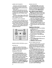
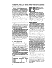
... the MONITOR MASTER control and MONITOR EQUALIZER. ond power amplifier, giving you to the external device. they will only play the mixer signals as shown in the diagram above, make these inputs to connect a sec- POWER AMP ROUTING AMP 1 AMP 2 MAIN MAIN MAIN MONITOR 408M 2 X 250 WATTS EFFECTS (OVERRIDES INTERNAL EFX) EFX FOOT SWITCH SEND POWER AMP 1 IN MAINS POWER AMP 2 IN MONITOR LINE OUT RETURN MIXER LINE OUT COMPRESSOR OUT IN TAPE IN U L R +15 LEVEL L R TAPE OUT...
... the MONITOR MASTER control and MONITOR EQUALIZER. ond power amplifier, giving you to the external device. they will only play the mixer signals as shown in the diagram above, make these inputs to connect a sec- POWER AMP ROUTING AMP 1 AMP 2 MAIN MAIN MAIN MONITOR 408M 2 X 250 WATTS EFFECTS (OVERRIDES INTERNAL EFX) EFX FOOT SWITCH SEND POWER AMP 1 IN MAINS POWER AMP 2 IN MONITOR LINE OUT RETURN MIXER LINE OUT COMPRESSOR OUT IN TAPE IN U L R +15 LEVEL L R TAPE OUT...
Owner's Manual
Page 25
... SPEAKER OUT RIGHT / MONITOR SPEAKER OUT OUTPUT POWER: 250 WATTS / CHANNEL MINIMUM SPEAKER LOAD: 2 OHMS / CHANNEL Stereo Version Speaker Connectors (408S) POWER AMP 1 / MAIN SPEAKER OUT POWER AMP 2 / MONITOR SPEAKER OUT OUTPUT POWER: 250 WATTS / CHANNEL MINIMUM SPEAKER LOAD: 2 OHMS / CHANNEL Mono Version Speaker Connectors (408M) 25 Plug the linecord into an AC socket properly configured for each amplifier. Guitar cords are wired in parallel so if you happen to lose the AC linecord, replacements are two SPEAKER OUT jacks for your speakers. The TAPE IN signal is...
... SPEAKER OUT RIGHT / MONITOR SPEAKER OUT OUTPUT POWER: 250 WATTS / CHANNEL MINIMUM SPEAKER LOAD: 2 OHMS / CHANNEL Stereo Version Speaker Connectors (408S) POWER AMP 1 / MAIN SPEAKER OUT POWER AMP 2 / MONITOR SPEAKER OUT OUTPUT POWER: 250 WATTS / CHANNEL MINIMUM SPEAKER LOAD: 2 OHMS / CHANNEL Mono Version Speaker Connectors (408M) 25 Plug the linecord into an AC socket properly configured for each amplifier. Guitar cords are wired in parallel so if you happen to lose the AC linecord, replacements are two SPEAKER OUT jacks for your speakers. The TAPE IN signal is...
Owner's Manual
Page 26
... speaker load on using a fan aimed at the heatsink to move air through the fins due to supply the correct voltage specified for the amplifier. When setting up . You can check it produces, the more peak output power will help minimize noise from the lights coupling into the audio (particularly if SCRs, or light-dimmer switches, are just below clipping, the powered...
... speaker load on using a fan aimed at the heatsink to move air through the fins due to supply the correct voltage specified for the amplifier. When setting up . You can check it produces, the more peak output power will help minimize noise from the lights coupling into the audio (particularly if SCRs, or light-dimmer switches, are just below clipping, the powered...

Owner's Manual
Page 27
... inputs of -balance stereo signal. • Try swapping sides: Turn off the powered mixer, swap the speaker cables at all the level and volume controls are properly adjusted. • Is the signal source working (and making union scale)? If it's a microphone, make sure the mic cable is set to "Tape," and make sure the tape deck's Tape/Source switch is in the speaker wire? Try unplugging any at the SPEAKER OUT jacks, turn up the INPUT LEVEL SET control. No sound! • Are the INPUT LEVEL SET controls turned all Mackie...
... inputs of -balance stereo signal. • Try swapping sides: Turn off the powered mixer, swap the speaker cables at all the level and volume controls are properly adjusted. • Is the signal source working (and making union scale)? If it's a microphone, make sure the mic cable is set to "Tape," and make sure the tape deck's Tape/Source switch is in the speaker wire? Try unplugging any at the SPEAKER OUT jacks, turn up the INPUT LEVEL SET control. No sound! • Are the INPUT LEVEL SET controls turned all Mackie...
Owner's Manual
Page 28
... RETURN jack(s). • Make sure all the channel MONitor controls are routed near AC cables, power transformers, or other EMI-inducing devices. • Is there a light dimmer or other electronic device connected to each amplifier 2 ohms or greater? Bad sound! • Is it . Check the speaker connections and verify that all connections are tight and that the levels are no monitor signal present. Noise/Hum • Turn the channel VOLUME...
... RETURN jack(s). • Make sure all the channel MONitor controls are routed near AC cables, power transformers, or other EMI-inducing devices. • Is there a light dimmer or other electronic device connected to each amplifier 2 ohms or greater? Bad sound! • Is it . Check the speaker connections and verify that all connections are tight and that the levels are no monitor signal present. Noise/Hum • Turn the channel VOLUME...
Owner's Manual
Page 32
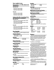
...% @ 4Ω Signal-to-Noise Ratio > 105 dB below rated power into 8Ω Channel Separation > 75 dB @ 1kHz Damping Factor > 250 @ 1kHz Amp Input Impedance 10kΩ unbalanced, 20kΩ balanced Input Sensitivity 406M, 408M, 408S 1.35 volts (+4.8 dBu) for rated power into 4 ohms 808M, 808S 1.76 volts (+7.1 dBu) for rated power into 4 ohms Gain (Amp In to Speaker Out) 26.4 dB (21V/V) Maximum Input Level 9.75 volts...
...% @ 4Ω Signal-to-Noise Ratio > 105 dB below rated power into 8Ω Channel Separation > 75 dB @ 1kHz Damping Factor > 250 @ 1kHz Amp Input Impedance 10kΩ unbalanced, 20kΩ balanced Input Sensitivity 406M, 408M, 408S 1.35 volts (+4.8 dBu) for rated power into 4 ohms 808M, 808S 1.76 volts (+7.1 dBu) for rated power into 4 ohms Gain (Amp In to Speaker Out) 26.4 dB (21V/V) Maximum Input Level 9.75 volts...


