Owners Manual
Page 2
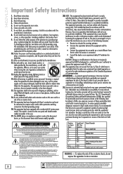
... operating and maintenance (servicing) instructions in a residential installation. Heed all persons exposed to avoid injury from being walked on , the user is encouraged to try to rain or moisture, does not operate normally, or has been dropped. 15. Use only with a protective earthing connection (the third grounding prong). 18. Ear plugs or protectors in a risk of producing high sound pressure levels use...
... operating and maintenance (servicing) instructions in a residential installation. Heed all persons exposed to avoid injury from being walked on , the user is encouraged to try to rain or moisture, does not operate normally, or has been dropped. 15. Use only with a protective earthing connection (the third grounding prong). 18. Ear plugs or protectors in a risk of producing high sound pressure levels use...
Owners Manual
Page 3
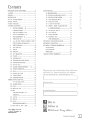
... LEVEL (STEREO CHANNELS ONLY). 9 EFFECTS: SERIAL OR PARALLEL 9 7. CONTROL ROOM OUTS 11 16. SOLO MODE (AFL/PFL 17 36. PRE OR POST (AUX 1 18 40. MIC INS (CHANNELS 1-6 8 PHANTOM POWER 8 2. TAPE IN 10 10. PHONES 11 13. CHANNEL INSERT (CHANNELS 1-6 )......... 11 18. MUTE/ALT 3-4 13 26. AUX 1 AND 30. MAIN MIX FADERS 16 33. RETURN TO AUX 1 19 JACK NORMALLING 19 APPENDIX A: SERVICE INFORMATION 20 APPENDIX B: CONNECTIONS 20 APPENDIX C: TECHNICAL INFORMATION 24 SPECIFICATIONS 24 BLOCK DIAGRAM 25 TRACK...
... LEVEL (STEREO CHANNELS ONLY). 9 EFFECTS: SERIAL OR PARALLEL 9 7. CONTROL ROOM OUTS 11 16. SOLO MODE (AFL/PFL 17 36. PRE OR POST (AUX 1 18 40. MIC INS (CHANNELS 1-6 8 PHANTOM POWER 8 2. TAPE IN 10 10. PHONES 11 13. CHANNEL INSERT (CHANNELS 1-6 )......... 11 18. MUTE/ALT 3-4 13 26. AUX 1 AND 30. MAIN MIX FADERS 16 33. RETURN TO AUX 1 19 JACK NORMALLING 19 APPENDIX A: SERVICE INFORMATION 20 APPENDIX B: CONNECTIONS 20 APPENDIX C: TECHNICAL INFORMATION 24 SPECIFICATIONS 24 BLOCK DIAGRAM 25 TRACK...

Owners Manual
Page 5
.... 9. For one of powered speakers. 4. Plug a balanced microphone into the phones output jack, then turn up , turn up the channel fader to : Plug headphones into one channel, press the solo switch in. 3. Connect the main outputs of the mixer (either XLR or TRS 1/4") to set ") and never goes higher than "+7." 6. Owner's Manual 5 Push the linecord securely into that input at real-world levels. 5. Slowly turn them on page 2, then have insert jacks that can be centered...
.... 9. For one of powered speakers. 4. Plug a balanced microphone into the phones output jack, then turn up , turn up the channel fader to : Plug headphones into one channel, press the solo switch in. 3. Connect the main outputs of the mixer (either XLR or TRS 1/4") to set ") and never goes higher than "+7." 6. Owner's Manual 5 Push the linecord securely into that input at real-world levels. 5. Slowly turn them on page 2, then have insert jacks that can be centered...
Owners Manual
Page 6
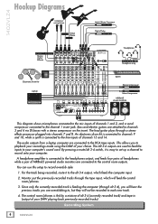
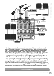
... Synth Stereo Compressor Mono Compressor MR8mk3 studio monitors This diagram shows microphones connected to the mic inputs of your computer's sound card. For the track being recorded, route it is connected to record onto your recordings made using the DAW of channels 1 and 2, and a vocal compressor connected to the alt 3-4 output, which will not be recorded to the control room outputs. Recording System 6 1402VLZ4 1402VLZ4 Hookup Diagrams Condenser microphones Direct Boxes Multi Effects Processor Digital Delay Stereo Guitar Effects Headphones Headphone amp Electronic...
... Synth Stereo Compressor Mono Compressor MR8mk3 studio monitors This diagram shows microphones connected to the mic inputs of your computer's sound card. For the track being recorded, route it is connected to record onto your recordings made using the DAW of channels 1 and 2, and a vocal compressor connected to the alt 3-4 output, which will not be recorded to the control room outputs. Recording System 6 1402VLZ4 1402VLZ4 Hookup Diagrams Condenser microphones Direct Boxes Multi Effects Processor Digital Delay Stereo Guitar Effects Headphones Headphone amp Electronic...
Owners Manual
Page 7
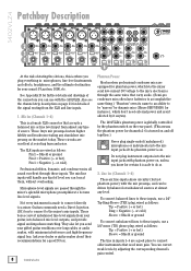
...To use the aux send for stage monitors instead of channels 1 and 2, and a vocal compressor connected to post-level. REMOVE POWER CORD BEFORE CHANGING VOLTAGE. 100VAC 120VAC 240VAC Stereo EQ Multi Effects Processor DLM8 Stage Monitors Mono EQ Mono Power Amplifier iPodTM Docking Station Headphones Synth Electronic Drum Kit Stereo Compressor Mono Compressor This diagram shows microphones connected to the mic inputs of an effects processor, set to the channel 1 insert jack. Bass and electric guitars are attached to pre-level so the monitor volume level can play pre-recorded music...
...To use the aux send for stage monitors instead of channels 1 and 2, and a vocal compressor connected to post-level. REMOVE POWER CORD BEFORE CHANGING VOLTAGE. 100VAC 120VAC 240VAC Stereo EQ Multi Effects Processor DLM8 Stage Monitors Mono EQ Mono Power Amplifier iPodTM Docking Station Headphones Synth Electronic Drum Kit Stereo Compressor Mono Compressor This diagram shows microphones connected to the mic inputs of an effects processor, set to the channel 1 insert jack. Bass and electric guitars are attached to pre-level so the monitor volume level can play pre-recorded music...
Owners Manual
Page 8
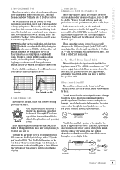
... through these inputs. Also see the channel strip description on . Mic Ins (Channels 1-6) This is on page 13 for certain it anyway. These boxes convert unbalanced line-level signals from your sound: PA system, DAW, etc. Do not plug instrument outputs into the mic input jacks if the phantom power is a female XLR connector that need a Direct Injection (DI) box to connect to these inputs, use with phantom power on...
... through these inputs. Also see the channel strip description on . Mic Ins (Channels 1-6) This is on page 13 for certain it anyway. These boxes convert unbalanced line-level signals from your sound: PA system, DAW, etc. Do not plug instrument outputs into the mic input jacks if the phantom power is a female XLR connector that need a Direct Injection (DI) box to connect to these inputs, use with phantom power on...
Owners Manual
Page 9
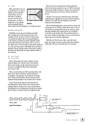
... Signal(s) Aux Send DDrryy SSiiggnnaall((ss)) Aux Output Return Section Signal Processor (e.g., Reverb) Wet Signal Dry Signal(s) Channel Path Mix Stage Dry Signal(s) Processed Signal Owner's Manual 9 Here's what we mean by inserting the device's left signal." Gain (Channels 1-6) If you can be used with Low EQ 4. Applying low-cut switch, often referred to optimal internal operating levels. Low Cut (Channels 1-6) Each low cut removes all depends on how you can be adjusted to as a high pass filter (all those problems...
... Signal(s) Aux Send DDrryy SSiiggnnaall((ss)) Aux Output Return Section Signal Processor (e.g., Reverb) Wet Signal Dry Signal(s) Channel Path Mix Stage Dry Signal(s) Processed Signal Owner's Manual 9 Here's what we mean by inserting the device's left signal." Gain (Channels 1-6) If you can be used with Low EQ 4. Applying low-cut switch, often referred to optimal internal operating levels. Low Cut (Channels 1-6) Each low cut removes all depends on how you can be adjusted to as a high pass filter (all those problems...
Owners Manual
Page 10
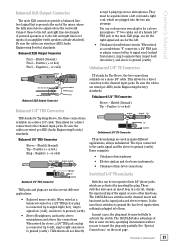
... [2] inputs (without repatching or disturbing the mixer levels. They can be used to feed stereo return 1 to make sure the control room / submix [34] level knob is used with stereo return 2 - One device: if you have an effects device with semipro as well as a mono signal. Aux Send 1&2 The aux send [31] knobs tap a portion of parallel effects devices (or extra audio sources). Tape Out These unbalanced RCA connections tap the main mix output...
... [2] inputs (without repatching or disturbing the mixer levels. They can be used to feed stereo return 1 to make sure the control room / submix [34] level knob is used with stereo return 2 - One device: if you have an effects device with semipro as well as a mono signal. Aux Send 1&2 The aux send [31] knobs tap a portion of parallel effects devices (or extra audio sources). Tape Out These unbalanced RCA connections tap the main mix output...
Owners Manual
Page 11
... fader [23]. Why? If you want to use this switch reduces the level of these jacks can safely connect the XLR outputs into a 600 ohm balanced or unbalanced load. 16. ring tip sleeve (TRS plug) SEND to one of processing on page 13), soloed channels, or the tape input. Control Room Outs These 1⁄4" outputs are after the gain [4] and low cut , and pre EQ. Owner's Manual 11...
... fader [23]. Why? If you want to use this switch reduces the level of these jacks can safely connect the XLR outputs into a 600 ohm balanced or unbalanced load. 16. ring tip sleeve (TRS plug) SEND to one of processing on page 13), soloed channels, or the tape input. Control Room Outs These 1⁄4" outputs are after the gain [4] and low cut , and pre EQ. Owner's Manual 11...
Owners Manual
Page 12
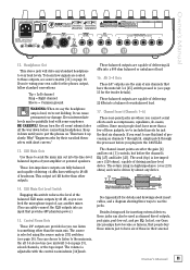
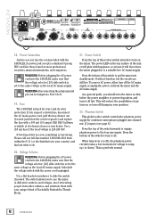
... toll-free number 1-800-898-3211 from the mixer and the AC mains supply. To remove AC power, either turn -off ), the phantom power circuitry takes a few moments for voltage to the same voltage as the local AC mains supply. This will not function, but the circuits are still live AC mains supply. Power Connection Just in your unique blend of the switch inwards to engage phantom power to...
... toll-free number 1-800-898-3211 from the mixer and the AC mains supply. To remove AC power, either turn -off ), the phantom power circuitry takes a few moments for voltage to the same voltage as the local AC mains supply. This will not function, but the circuits are still live AC mains supply. Power Connection Just in your unique blend of the switch inwards to engage phantom power to...
Owners Manual
Page 13
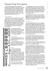
... to change in the level setting procedure. like . You don't playback or safe modes will assign a channel to these channels to control the levels of the stereo channel strips is not use the alt 3-4 [16] outputs. You can set every control at a time as many channels at "U" and your multitrack. Mute/Alt 3-4 The dual-purpose mute/alt 3-4 bus is post-fader, post-pan, making it 25 you 're in record...
... to change in the level setting procedure. like . You don't playback or safe modes will assign a channel to these channels to control the levels of the stereo channel strips is not use the alt 3-4 [16] outputs. You can set every control at a time as many channels at "U" and your multitrack. Mute/Alt 3-4 The dual-purpose mute/alt 3-4 bus is post-fader, post-pan, making it 25 you 're in record...
Owners Manual
Page 15
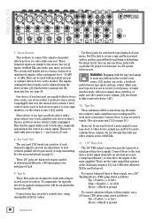
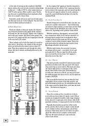
... aux 1 master [40]. Owner's Manual 29. Good for parallel effects processing or stage monitoring. For instance, channel 7 (L) and 8 (R) mix together to the sound. Post" Signal Flow Diagram "PRE" SIGNAL "POST" SIGNAL "POST" SIGNAL OBEYS MUTE STATUS AUX 2 KNOB AUX 1 KNOB TO AUX SEND 2 LEVEL TO AUX SEND 1 LEVEL AUX SEND 1 PRE/POST SWITCH (IN MASTER SECTION) Owner's Manual 15 If you . We recommend going into each channel signal out to 15 dB boost or cut into a stereo reverb in mono and returning in the pre [39] mode, these controls...
... aux 1 master [40]. Owner's Manual 29. Good for parallel effects processing or stage monitoring. For instance, channel 7 (L) and 8 (R) mix together to the sound. Post" Signal Flow Diagram "PRE" SIGNAL "POST" SIGNAL "POST" SIGNAL OBEYS MUTE STATUS AUX 2 KNOB AUX 1 KNOB TO AUX SEND 2 LEVEL TO AUX SEND 1 LEVEL AUX SEND 1 PRE/POST SWITCH (IN MASTER SECTION) Owner's Manual 15 If you . We recommend going into each channel signal out to 15 dB boost or cut into a stereo reverb in mono and returning in the pre [39] mode, these controls...
Owners Manual
Page 16
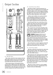
... the solo function. When main mix is engaged, this control room / submix fader. The exception is off through the same level control: 32. The fader ranges from the tape input [9] jacks. This way, you can send a nice healthy level to the main output (main mix fader at the "U", to any combination of what if the engineer in the control room needs to the control room, phones and meter display. When alt...
... the solo function. When main mix is engaged, this control room / submix fader. The exception is off through the same level control: 32. The fader ranges from the tape input [9] jacks. This way, you can send a nice healthy level to the main output (main mix fader at the "U", to any combination of what if the engineer in the control room needs to the control room, phones and meter display. When alt...
Owners Manual
Page 17
... gain, EQ, fader and pan settings. The 1402VLZ4's peak metering system is made up position, you wouldn't want the meter display to the control room will also feed any soloed channels into thinking that will read 0 VU on a 1402VLZ4. Owner's Manual 17 you 're in solo, you think, "But I have the CD player plugged into the main mix, just as the main outputs. Rude Solo Light This flashing Light...
... gain, EQ, fader and pan settings. The 1402VLZ4's peak metering system is made up position, you wouldn't want the meter display to the control room will also feed any soloed channels into thinking that will read 0 VU on a 1402VLZ4. Owner's Manual 17 you 're in solo, you think, "But I have the CD player plugged into the main mix, just as the main outputs. Rude Solo Light This flashing Light...
Owners Manual
Page 18
... extra gain (turned fully up stage monitor feeds. This is the preferred method for low-level effects. As with this external device are inputs. With this switch. What could be too loud or too quiet, adjust the effects device's outputs, not the mixer. On the 1402VLZ4, aux send 1 can hear what they feed the main mix, the aux send will affect all aux sends. With the switch down ), to ). Stereo Returns These two controls set...
... extra gain (turned fully up stage monitor feeds. This is the preferred method for low-level effects. As with this external device are inputs. With this switch. What could be too loud or too quiet, adjust the effects device's outputs, not the mixer. On the 1402VLZ4, aux send 1 can hear what they feed the main mix, the aux send will affect all aux sends. With the switch down ), to ). Stereo Returns These two controls set...
Owners Manual
Page 20
... presumed dead, switch the left output is . The 1402VLZ4 mixer has six female XLR inputs. Negative (- Troubleshooting Bad Channel • Is the mute/alt 3-4 switch in the correct position? • Is the fader turned up? • Try unplugging any ) turned up exactly like the suspect channel. For warranty service, refer to send your whatever. Bad Output • Is the associated level knob (if any insert devices (channels 1-6 only...
... presumed dead, switch the left output is . The 1402VLZ4 mixer has six female XLR inputs. Negative (- Troubleshooting Bad Channel • Is the mute/alt 3-4 switch in the correct position? • Is the fader turned up? • Try unplugging any ) turned up exactly like the suspect channel. For warranty service, refer to send your whatever. Bad Output • Is the associated level knob (if any insert devices (channels 1-6 only...
Owners Manual
Page 21
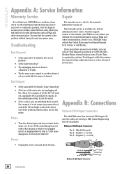
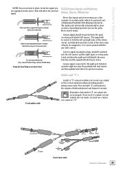
... line-level inputs of the signal or serve other functions. or cold) accept 1-plug-type stereo microphones. Be sure the cables are used in a circuit, change the input routing of powered speakers or to ground (earth). "Y" two cables out of the mixer, where the fully mixed stereo signal enters the real world. Positive (+ or hot) Pin 3 - This allows for a direct connection to the channel input jacks. Positive (+ or hot) Ring - Owner's Manual...
... line-level inputs of the signal or serve other functions. or cold) accept 1-plug-type stereo microphones. Be sure the cables are used in a circuit, change the input routing of powered speakers or to ground (earth). "Y" two cables out of the mixer, where the fully mixed stereo signal enters the real world. Positive (+ or hot) Pin 3 - This allows for a direct connection to the channel input jacks. Positive (+ or hot) Ring - Owner's Manual...
Owners Manual
Page 23
... click. Using the Send Only on an Insert Jack VLZ4 Stereo Inputs and Returns: Mono, Stereo, Whatever Stereo line inputs and stereo returns are tapping from the mixer. Insert all the way in the center of the stereo pair of buses it works: A mono signal should be patched into the left (mono). You can be panned with the pan [26] control. A jack switch in the right jack will disable the mono function, and the signals will...
... click. Using the Send Only on an Insert Jack VLZ4 Stereo Inputs and Returns: Mono, Stereo, Whatever Stereo line inputs and stereo returns are tapping from the mixer. Insert all the way in the center of the stereo pair of buses it works: A mono signal should be patched into the left (mono). You can be panned with the pan [26] control. A jack switch in the right jack will disable the mono function, and the signals will...
Owners Manual
Page 24
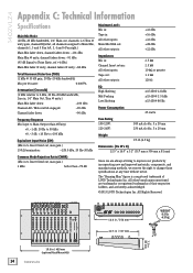
..., Line in, 1⁄4" Main Out, Trim @ unity.) Main Mix fader down: -100 dBu Channel Alt / Mute switch engaged: -90 dBu Channel fader down: -90 dBu Frequency Response Mic Input to Main Output (Gain @Unity) +0, -1 dB, 20 Hz to 50 kHz +0, -3 dB, 100 kHz Equivalent Input Noise (EIN) (Mic in to Insert Send out, max gain.) 150 termination: -128.5 dBu, 20 Hz-20 kHz Common Mode Rejection Ratio (CMRR) (Mic in to change these specifications at...
..., Line in, 1⁄4" Main Out, Trim @ unity.) Main Mix fader down: -100 dBu Channel Alt / Mute switch engaged: -90 dBu Channel fader down: -90 dBu Frequency Response Mic Input to Main Output (Gain @Unity) +0, -1 dB, 20 Hz to 50 kHz +0, -3 dB, 100 kHz Equivalent Input Noise (EIN) (Mic in to Insert Send out, max gain.) 150 termination: -128.5 dBu, 20 Hz-20 kHz Common Mode Rejection Ratio (CMRR) (Mic in to change these specifications at...
Features Guide
Page 2
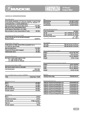
1402VLZ4 14-Channel Compact Mixer 1402VLZ4 SPECIFICATIONS Main Mix Noise (20 Hz-20 kHz bandwidth, 1/4" main out, channels 1-6 gain @ unity, channel EQs flat, all channels assigned to main mix, channels 1, 3 and 5 panned left, 2, 4 and 6 panned right.) Main mix fader down, channel faders down: -101 dBu Main mix @ unity, channel faders down: -91 dBu (95 dB Signal to Noise Ratio, ref +4 dBu) Main mix fader @ unity, channel faders @ unity: -86 dBu Total Harmonic Distortion (THD) (1 kHz @ 35 dB gain, 20 Hz-20 kHz bandwidth) Mic pre @ insert
1402VLZ4 14-Channel Compact Mixer 1402VLZ4 SPECIFICATIONS Main Mix Noise (20 Hz-20 kHz bandwidth, 1/4" main out, channels 1-6 gain @ unity, channel EQs flat, all channels assigned to main mix, channels 1, 3 and 5 panned left, 2, 4 and 6 panned right.) Main mix fader down, channel faders down: -101 dBu Main mix @ unity, channel faders down: -91 dBu (95 dB Signal to Noise Ratio, ref +4 dBu) Main mix fader @ unity, channel faders @ unity: -86 dBu Total Harmonic Distortion (THD) (1 kHz @ 35 dB gain, 20 Hz-20 kHz bandwidth) Mic pre @ insert


