User Guide
Page 3
... from the user's manual, please contact your place of breakage. ■ DO NOT LEAVE THIS EQUIPMENT IN AN ENVIRONMENT ABOVE 60oC (140oF), IT MAY DAMAGE THE EQUIPMENT. Do not place any of the following help resources for further guidance. ◙ Visit the MSI website for technical guide, BIOS updates, driver updates, and other information: http://www.msi.com/service/download ◙...
... from the user's manual, please contact your place of breakage. ■ DO NOT LEAVE THIS EQUIPMENT IN AN ENVIRONMENT ABOVE 60oC (140oF), IT MAY DAMAGE THE EQUIPMENT. Do not place any of the following help resources for further guidance. ◙ Visit the MSI website for technical guide, BIOS updates, driver updates, and other information: http://www.msi.com/service/download ◙...
User Guide
Page 9
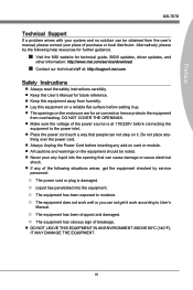
... Electronic Equipment) Statement vi Chapter 1 Getting Started 1-1 Packing Contents 1-2 Optional Accessories 1-2 Assembly Precautions 1-3 Mainboard Specifications 1-4 Connectors Quick Guide 1-6 Back Panel Quick Guide 1-8 CPU (Central Processing Unit 1-10 Mounting Screw Holes 1-14 Power Supply 1-15 Memory 1-16 Expansion Slots 1-18 Video/ Graphics Cards 1-19 Internal Connectors 1-22 Jumper 1-28 Chapter 2 BIOS Setup 2-1 Entering 2-2 Overview 2-2 Boot device priority bar 2-3 Operation 2-4 SETTINGS 2-5 OC 2-10 ECO 2-15 BROWSER 2-16 Installing Winki 2-16 UTILITIES 2-17 ix
... Electronic Equipment) Statement vi Chapter 1 Getting Started 1-1 Packing Contents 1-2 Optional Accessories 1-2 Assembly Precautions 1-3 Mainboard Specifications 1-4 Connectors Quick Guide 1-6 Back Panel Quick Guide 1-8 CPU (Central Processing Unit 1-10 Mounting Screw Holes 1-14 Power Supply 1-15 Memory 1-16 Expansion Slots 1-18 Video/ Graphics Cards 1-19 Internal Connectors 1-22 Jumper 1-28 Chapter 2 BIOS Setup 2-1 Entering 2-2 Overview 2-2 Boot device priority bar 2-3 Operation 2-4 SETTINGS 2-5 OC 2-10 ECO 2-15 BROWSER 2-16 Installing Winki 2-16 UTILITIES 2-17 ix
User Guide
Page 14
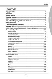
Getting Started Mainboard Specifications Processor Support ■ Intel® CoreTM i7/ CoreTM i5 /CoreTM i3/ Pentium®/ Celeron® processors for the LGA1155 package (For the latest information about CPU, please visit http://www.msi.com/service/cpu-support) Chipset ■ Intel® Z68 (B3) chipset Memory Support ■ 4x DDR3 DIMMs support DDR3 2133*(OC)/ 1866*(OC)/ 1600*(OC)/ 1333/ 1066 DRAM (32GB Max) ■ Supports Dual-Channel mode (*OC = OverClocking, for more...
Getting Started Mainboard Specifications Processor Support ■ Intel® CoreTM i7/ CoreTM i5 /CoreTM i3/ Pentium®/ Celeron® processors for the LGA1155 package (For the latest information about CPU, please visit http://www.msi.com/service/cpu-support) Chipset ■ Intel® Z68 (B3) chipset Memory Support ■ 4x DDR3 DIMMs support DDR3 2133*(OC)/ 1866*(OC)/ 1600*(OC)/ 1333/ 1066 DRAM (32GB Max) ■ Supports Dual-Channel mode (*OC = OverClocking, for more...

User Guide
Page 15
...1-5 PCI_E1 supports up to PCIe x16 speed - Chapter 1 MS-7676 Connectors & Buttons ■ Back panel - 1x PS/2 keyboard/ mouse combo port - 6x USB 2.0 ports - 2x USB 3.0 ports - 1x LAN port - 1x VGA port ** - 1x DVI-D port ** - 1x HDMI port ** - 6x audio ports **(The VGA, DVI-D and HDMI ports only work with the CPU's Integrated Graphics Processor) ■ On-Board - 3x USB 2.0 connectors - 1x Chassis Intrusion connector - 1x S/PDIF-Out connector - 1x Front Panel Audio connector - 1x TPM Module connector - 1x Parallel connector - 1x Serial connector Slots ■ 2x PCIe 3.0 x16 slots -
...1-5 PCI_E1 supports up to PCIe x16 speed - Chapter 1 MS-7676 Connectors & Buttons ■ Back panel - 1x PS/2 keyboard/ mouse combo port - 6x USB 2.0 ports - 2x USB 3.0 ports - 1x LAN port - 1x VGA port ** - 1x DVI-D port ** - 1x HDMI port ** - 6x audio ports **(The VGA, DVI-D and HDMI ports only work with the CPU's Integrated Graphics Processor) ■ On-Board - 3x USB 2.0 connectors - 1x Chassis Intrusion connector - 1x S/PDIF-Out connector - 1x Front Panel Audio connector - 1x TPM Module connector - 1x Parallel connector - 1x Serial connector Slots ■ 2x PCIe 3.0 x16 slots -

User Guide
Page 25
....+3dV2.5+4V5.GVround ATX 4-pin Power Connector: JPWR2 This connector provides 12V power to the CPU. 2.G1.rGouronudnd 4.+31.+21V2V Important Make sure that all the power cables are securely connected to a proper ATX power supply to connect an ATX 24-pin power supply. Chapter 1 MS-7676 Power Supply ATX 24-pin Power Connector: JPWR1 This connector allows you to ensure stable operation of the mainboard. 1-15 To connect the ATX 24-pin power supply, align the power supply cable with the connector and firmly...
....+3dV2.5+4V5.GVround ATX 4-pin Power Connector: JPWR2 This connector provides 12V power to the CPU. 2.G1.rGouronudnd 4.+31.+21V2V Important Make sure that all the power cables are securely connected to a proper ATX power supply to connect an ATX 24-pin power supply. Chapter 1 MS-7676 Power Supply ATX 24-pin Power Connector: JPWR1 This connector allows you to ensure stable operation of the mainboard. 1-15 To connect the ATX 24-pin power supply, align the power supply cable with the connector and firmly...

User Guide
Page 33
... to connect a fan directly to a power supply. • Before first boot up, ensure that there are not enough ports on -board, you must use a specially designed fan with +12V. The Control Center utility can be installed to automatically control the CPU fan speeds according to the CPU's and system's temperature. • If there are no cables impeding any available system fan connector. Chapter 1 MS-7676 Fan Power Connectors: CPUFAN,SYSFAN1~2 The fan power connectors support system cooling fans with a speed...
... to connect a fan directly to a power supply. • Before first boot up, ensure that there are not enough ports on -board, you must use a specially designed fan with +12V. The Control Center utility can be installed to automatically control the CPU fan speeds according to the CPU's and system's temperature. • If there are no cables impeding any available system fan connector. Chapter 1 MS-7676 Fan Power Connectors: CPUFAN,SYSFAN1~2 The fan power connectors support system cooling fans with a speed...

User Guide
Page 44
... cannot switch between AHCI and IDE if you to RAM. If you have your BIOS/reset to default settings, you will provide you to enable/ disable the onboard LAN controller 1. ▶ LAN Option ROM This item is used to decide whether to invoke the Boot ROM of the chipset. Hardware remains on the case to indicate sleep/ suspend state. [Single] The power LED turns off during the sleep/suspend mode. [Dual] The power LED changes its color to indicate the sleep/suspend...
... cannot switch between AHCI and IDE if you to RAM. If you have your BIOS/reset to default settings, you will provide you to enable/ disable the onboard LAN controller 1. ▶ LAN Option ROM This item is used to decide whether to invoke the Boot ROM of the chipset. Hardware remains on the case to indicate sleep/ suspend state. [Single] The power LED turns off during the sleep/suspend mode. [Dual] The power LED changes its color to indicate the sleep/suspend...

User Guide
Page 46
... event functions. ▶ Restore after a power failure or interrupt occurs. BIOS Setup ▶ Parallel(LPT) Port Settings Select an address and corresponding interrupt for the parallel port. ▶ Device Mode Select the device mode for the parallel port. ▶ Hardware Monitor Press to enter the sub-menu. ▶ CPU Smart Fan Target Controls CPU fan speed automatically depending on a specific date/hour/minute/second specified in standby mode. Settings are: [Power Off] Always leaves the computer...
... event functions. ▶ Restore after a power failure or interrupt occurs. BIOS Setup ▶ Parallel(LPT) Port Settings Select an address and corresponding interrupt for the parallel port. ▶ Device Mode Select the device mode for the parallel port. ▶ Hardware Monitor Press to enter the sub-menu. ▶ CPU Smart Fan Target Controls CPU fan speed automatically depending on a specific date/hour/minute/second specified in standby mode. Settings are: [Power Off] Always leaves the computer...

User Guide
Page 47
... boot. == Boot Option Priorities== ▶ 1st~8th Boot These items are used to prioritize the installed boot devices. ▶ USB KEY Drive BBS Priorities/ UEFI Boot Drive BBS Priorities ▶ 1st~8th Boot These items are used to load the optimized default values set by the BIOS vendor. == Boot Override == The installed storage devices will be awakened from what power saving modes when input signal of them be a boot device. ▶ Built-in EFI Shell Use this item to enter...
... boot. == Boot Option Priorities== ▶ 1st~8th Boot These items are used to prioritize the installed boot devices. ▶ USB KEY Drive BBS Priorities/ UEFI Boot Drive BBS Priorities ▶ 1st~8th Boot These items are used to load the optimized default values set by the BIOS vendor. == Boot Override == The installed storage devices will be awakened from what power saving modes when input signal of them be a boot device. ▶ Built-in EFI Shell Use this item to enter...

User Guide
Page 49
... related "Advanced DRAM Configuration" sub-menu manually. ▶ Advanced DRAM Configuration Press to enter the sub-menu. ▶ Command Rate This setting controls the DRAM command rate. ▶ tCL Controls CAS latency which automatically boosts CPU performance above rated specifications (when applications requests the highest performance state of the processor). ▶ OC Genie Button Operation This item is used to enable/disable the OC Genie button operation. ▶ DRAM Frequency This item...
... related "Advanced DRAM Configuration" sub-menu manually. ▶ Advanced DRAM Configuration Press to enter the sub-menu. ▶ Command Rate This setting controls the DRAM command rate. ▶ tCL Controls CAS latency which automatically boosts CPU performance above rated specifications (when applications requests the highest performance state of the processor). ▶ OC Genie Button Operation This item is used to enable/disable the OC Genie button operation. ▶ DRAM Frequency This item...
User Guide
Page 51
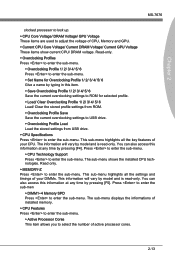
... profile. ▶ Load/ Clear Overclocking Profile 1/ 2/ 3/ 4/ 5/ 6 Load/ Clear the stored profile settings from ROM. ▶ Overclocking Profile Save Save the current overclocking settings to USB drive. ▶ Overclocking Profile Load Load the stored settings from USB drive. ▶ CPU Specifications Press to enter the sub-menu. Press to enter the sub-menu. ▶ CPU Technology Support Press to enter the sub-menu. Press to enter the sub-men ▶ DIMM1~4 Memory SPD Press to enter the sub-menu. You can also access this item...
... profile. ▶ Load/ Clear Overclocking Profile 1/ 2/ 3/ 4/ 5/ 6 Load/ Clear the stored profile settings from ROM. ▶ Overclocking Profile Save Save the current overclocking settings to USB drive. ▶ Overclocking Profile Load Load the stored settings from USB drive. ▶ CPU Specifications Press to enter the sub-menu. Press to enter the sub-menu. ▶ CPU Technology Support Press to enter the sub-menu. Press to enter the sub-men ▶ DIMM1~4 Memory SPD Press to enter the sub-menu. You can also access this item...
User Guide
Page 55
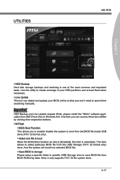
... selected BIOS file. ▶ Save BIOS to storage Please setup a specific folder in specific USB/ Storage drive to create an image of the most common and important tasks. Use this item is one file to boot When the BIOS Boot function as sets to [Enabled], this utility to save BIOS file from MSI Driver Disc in Windows first. Important HDD Backup and Live Update request Winki, please install the "Winki" software application from BIOS ROM chip data. Note: it only supports...
... selected BIOS file. ▶ Save BIOS to storage Please setup a specific folder in specific USB/ Storage drive to create an image of the most common and important tasks. Use this item is one file to boot When the BIOS Boot function as sets to [Enabled], this utility to save BIOS file from MSI Driver Disc in Windows first. Important HDD Backup and Live Update request Winki, please install the "Winki" software application from BIOS ROM chip data. Note: it only supports...
User Guide
Page 56
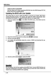
... version and model of BIOS and download the appropriate file. 5. Click the next button . 4. Important Do not unplug or shut off your motherboard BIOS when updating. 2-18 on the BIOS UTILITIES menu. (The Winki must be 2. Live Update will update the BIOS automatically when connecting to select a particular BIOS file from the USB/ Storage (FAT/ 32 format only) drive for updating BIOS. Incorrect BIOS flashing can cause the motherboard to update the BIOS by click the setting button if necessary. 3. BIOS Setup...
... version and model of BIOS and download the appropriate file. 5. Click the next button . 4. Important Do not unplug or shut off your motherboard BIOS when updating. 2-18 on the BIOS UTILITIES menu. (The Winki must be 2. Live Update will update the BIOS automatically when connecting to select a particular BIOS file from the USB/ Storage (FAT/ 32 format only) drive for updating BIOS. Incorrect BIOS flashing can cause the motherboard to update the BIOS by click the setting button if necessary. 3. BIOS Setup...

User Guide
Page 57
... USB drive. ▶ Chassis Intrusion Configuration Press to abort the selection. To clear a set password from CMOS memory. SECURITY MS-7676 Chapter 2 ▶ Administrator Password Set the administrative password that will be required to enter the BIOS. ▶ User Password Set the user password that will replace any previous set password, press when you are prompted to enter a new password. Once the password is disabled, you can enter the setup and OS without authorization. ▶ U-Key Enable or disable USB driver device as sets to enter...
... USB drive. ▶ Chassis Intrusion Configuration Press to abort the selection. To clear a set password from CMOS memory. SECURITY MS-7676 Chapter 2 ▶ Administrator Password Set the administrative password that will be required to enter the BIOS. ▶ User Password Set the user password that will replace any previous set password, press when you are prompted to enter a new password. Once the password is disabled, you can enter the setup and OS without authorization. ▶ U-Key Enable or disable USB driver device as sets to enter...

User Guide
Page 58
BIOS Setup ▶ Chassis Intrusion Enables or disables the feature of the field will return to [Reset]. To clear the warning logs, set the field to [Enabled] later. 2-20 The setting of recording the chassis intrusion status and issuing a warning message if opened.
BIOS Setup ▶ Chassis Intrusion Enables or disables the feature of the field will return to [Reset]. To clear the warning logs, set the field to [Enabled] later. 2-20 The setting of recording the chassis intrusion status and issuing a warning message if opened.

User Guide
Page 66
.... Supports Hot-plug-n-play feature. 3. RAID 0 breaks the data into blocks which are written to 6 Gb/s. B-2 Intel® Rapid Storage Technology is the advanced ability for RAID 5 mode is created, complete capacity of the Master drive will be less than or equal to a designated Recovery drive. Intel RAID Introduction The mainboard comes with CRC error checking. 2. Serial ATA uses long, thin cables, making it easier to connect your drive...
.... Supports Hot-plug-n-play feature. 3. RAID 0 breaks the data into blocks which are written to 6 Gb/s. B-2 Intel® Rapid Storage Technology is the advanced ability for RAID 5 mode is created, complete capacity of the Master drive will be less than or equal to a designated Recovery drive. Intel RAID Introduction The mainboard comes with CRC error checking. 2. Serial ATA uses long, thin cables, making it easier to connect your drive...
User Guide
Page 67
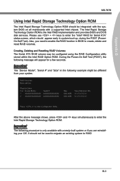
... Resetting RAID Volumes: The Serial ATA RAID volume may be used to migrate an existing system to enable the RAID function in system boot-up, during the POST (PowerOn Self Test). It should not be configured using the RAID Configuration utility stored within the Intel RAID Option ROM. Physical Disks: Port Device Model 1 XXXXXXXXXXXXX 2 XXXXXXXXXXXXX Serial # XXXXXXXXXXXXX XXXXXXXXXXXXX Size XXX.XGB XXX.XGB Type/Status(Vol ID) Non-RAID Disk Non-RAID Disk Press to enter the Intel Rapid Storage Technology Option ROM...
... Resetting RAID Volumes: The Serial ATA RAID volume may be used to migrate an existing system to enable the RAID function in system boot-up, during the POST (PowerOn Self Test). It should not be configured using the RAID Configuration utility stored within the Intel RAID Option ROM. Physical Disks: Port Device Model 1 XXXXXXXXXXXXX 2 XXXXXXXXXXXXX Serial # XXXXXXXXXXXXX XXXXXXXXXXXXX Size XXX.XGB XXX.XGB Type/Status(Vol ID) Non-RAID Disk Non-RAID Disk Press to enter the Intel Rapid Storage Technology Option ROM...
User Guide
Page 74
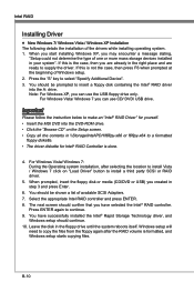
.... • Insert the MSI DVD into the A: drive. Press the "S" key to continue. 9. For Windows Vista/ Windows 7 you can use the USB floppy drive only. Important Please follow the instruction below to install a third party SCSI or RAID driver. 5. Press ENTER again to select "Specify Additional Device". 3. Windows setup will need to copy the files from the floppy again after selecting the location to install Vista / Windows 7 click on the Setup screen. • Copy all...
.... • Insert the MSI DVD into the A: drive. Press the "S" key to continue. 9. For Windows Vista/ Windows 7 you can use the USB floppy drive only. Important Please follow the instruction below to install a third party SCSI or RAID driver. 5. Press ENTER again to select "Specify Additional Device". 3. Windows setup will need to copy the files from the floppy again after selecting the location to install Vista / Windows 7 click on the Setup screen. • Copy all...
User Guide
Page 75
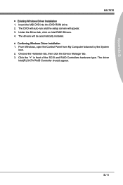
... and RAID Controllers hardware type. B-11 The DVD will auto-run and the setup screen will be automatically installed. ■ Confirming Windows Driver Installation 1. Under the Driver tab, click on Intel RAID Drivers. 4. Choose the Hardware tab, then click the Device Manager tab. 3. Insert the MSI DVD into the DVD-ROM drive. 2. Appendix B MS-7676 ■ Existing Windows Driver Installation 1. From Windows, open the Control Panel from My Computer followed by the System icon. 2. The driver Intel(R) SATA RAID Controller...
... and RAID Controllers hardware type. B-11 The DVD will auto-run and the setup screen will be automatically installed. ■ Confirming Windows Driver Installation 1. Under the Driver tab, click on Intel RAID Drivers. 4. Choose the Hardware tab, then click the Device Manager tab. 3. Insert the MSI DVD into the DVD-ROM drive. 2. Appendix B MS-7676 ■ Existing Windows Driver Installation 1. From Windows, open the Control Panel from My Computer followed by the System icon. 2. The driver Intel(R) SATA RAID Controller...
User Guide
Page 78
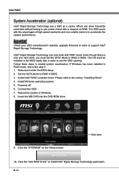
... install Intel® Rapid Storage Technology application. Click the "Intel RAID Driver" to Windows. 8. Which can only work with the advantages of high-speed read/write and non-volatile memory to RAID in BIOS. Reboot and enter the BIOS steup. 2. Insert the MSI DVD into the DVD-ROM drive. 9. The SSD cache with RAID mode. Intel® Rapid Storage Technology can store frequently used data without having to support Intel® Rapid Storage Technology. The OS must set...
... install Intel® Rapid Storage Technology application. Click the "Intel RAID Driver" to Windows. 8. Which can only work with the advantages of high-speed read/write and non-volatile memory to RAID in BIOS. Reboot and enter the BIOS steup. 2. Insert the MSI DVD into the DVD-ROM drive. 9. The SSD cache with RAID mode. Intel® Rapid Storage Technology can store frequently used data without having to support Intel® Rapid Storage Technology. The OS must set...


