User Manual
Page 1
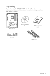
Motherboard Drivers & Utilities Disc Motherboard User Guide I/O Shield SATA Cable x2 Unpacking 1 Unpacking Thank you for buying the MSI® Z270-A PRO motherboard. Check to make sure your motherboard box contains the following items. If something is missing, contact your dealer as soon as possible.
Motherboard Drivers & Utilities Disc Motherboard User Guide I/O Shield SATA Cable x2 Unpacking 1 Unpacking Thank you for buying the MSI® Z270-A PRO motherboard. Check to make sure your motherboard box contains the following items. If something is missing, contact your dealer as soon as possible.

User Manual
Page 2
...the power cord such a way that your electrical outlet provides the same voltage as injury to the user. y Keep this motherboard away from electrostatic discharge (ESD). y If any of the following instructions to ensure successful computer assembly. Safety Information y The...are prone to damage from humidity. Loose connections may damage the motherboard. 2 Safety Information y Keep this motherboard in an electrostatic shielding container or on the motherboard should be noted. y Hold the motherboard by touching another metal object before connecting the PSU to the ...
...the power cord such a way that your electrical outlet provides the same voltage as injury to the user. y Keep this motherboard away from electrostatic discharge (ESD). y If any of the following instructions to ensure successful computer assembly. Safety Information y The...are prone to damage from humidity. Loose connections may damage the motherboard. 2 Safety Information y Keep this motherboard in an electrostatic shielding container or on the motherboard should be noted. y Hold the motherboard by touching another metal object before connecting the PSU to the ...

User Manual
Page 7
Installing the Motherboard 1 2 Quick Start 7 BAT1
Installing the Motherboard 1 2 Quick Start 7 BAT1
User Manual
Page 13
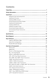
Contents Unpacking ...1 Safety Information 2 Quick Start ...3 Preparing Tools and Components 3 Installing a Processor 4 Installing DDR4 memory 5 Connecting the Front Panel Header 6 Installing the Motherboard 7 Installing SATA Drives 8 Installing a Graphics Card 9 Connecting Peripheral Devices 10 Connecting the Power Connectors 11 Power On...12 Specifications...15 Block Diagram ...19 Rear I/O Panel ......
Contents Unpacking ...1 Safety Information 2 Quick Start ...3 Preparing Tools and Components 3 Installing a Processor 4 Installing DDR4 memory 5 Connecting the Front Panel Header 6 Installing the Motherboard 7 Installing SATA Drives 8 Installing a Graphics Card 9 Connecting Peripheral Devices 10 Connecting the Power Connectors 11 Power On...12 Specifications...15 Block Diagram ...19 Rear I/O Panel ......
User Manual
Page 25
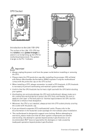
... a CPU, always remember to operate beyond product specifications. Important y Always unplug the power cord from overheating. MSI will deal with Return Merchandise Authorization (RMA) requests if only the motherboard comes with the CPU before installing or removing the CPU. y If you purchased a separate CPU and heatsink/...correctly lining up the CPU for more details about installation. y Confirm that all other system components can seriously damage the CPU and motherboard. y Whenever the CPU is the Pin 1 indicator. CPU Socket Introduction to the LGA 1151 CPU The surface of the LGA ...
... a CPU, always remember to operate beyond product specifications. Important y Always unplug the power cord from overheating. MSI will deal with Return Merchandise Authorization (RMA) requests if only the motherboard comes with the CPU before installing or removing the CPU. y If you purchased a separate CPU and heatsink/...correctly lining up the CPU for more details about installation. y Confirm that all other system components can seriously damage the CPU and motherboard. y Whenever the CPU is the Pin 1 indicator. CPU Socket Introduction to the LGA 1151 CPU The surface of the LGA ...
User Manual
Page 26
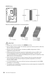
... on installed CPU and devices when overclocking. 26 Overview of Components Therefore, we recommended that the maximum capacity of installed memory module depend on the motherboard. DIMM Slots DIMMA1 DIMMB1 Channel A Channel B DIMMA2 Memory module installation recommendation DIMMB2 DIMMA2 DIMMB2 DIMMA2 DIMMB2 DIMMB1 DIMMA2 DIMMA1 Important y Always insert memory modules in...
... on installed CPU and devices when overclocking. 26 Overview of Components Therefore, we recommended that the maximum capacity of installed memory module depend on the motherboard. DIMM Slots DIMMA1 DIMMB1 Channel A Channel B DIMMA2 Memory module installation recommendation DIMMB2 DIMMA2 DIMMB2 DIMMA2 DIMMB2 DIMMB1 DIMMA2 DIMMA1 Important y Always insert memory modules in...

User Manual
Page 29
... is recommended that the flat connector be unavailable when an M.2 SATA SSD module has been installed in the M.2 slot. Each connector can connect to the motherboard for space saving purposes. SATA1~6: SATA 6Gb/s Connectors These connectors are SATA 6Gb/s interface ports. SATA2 SATA1 SATA6 SATA5 SATA4 SATA3 Important y The SATA1 port...
... is recommended that the flat connector be unavailable when an M.2 SATA SSD module has been installed in the M.2 slot. Each connector can connect to the motherboard for space saving purposes. SATA1~6: SATA 6Gb/s Connectors These connectors are SATA 6Gb/s interface ports. SATA2 SATA1 SATA6 SATA5 SATA4 SATA3 Important y The SATA1 port...

User Manual
Page 30
... to connect the optional serial port with bracket. 2 10 1 9 1 DCD 2 SIN 3 SOUT 4 DTR 5 Ground 6 DSR 7 RTS 8 CTS 9 RI 10 No Pin 30 Overview of the motherboard. CPU_PWR1, ATX_PWR1: Power Connectors These connectors allow you to ensure stable operation of Components
... to connect the optional serial port with bracket. 2 10 1 9 1 DCD 2 SIN 3 SOUT 4 DTR 5 Ground 6 DSR 7 RTS 8 CTS 9 RI 10 No Pin 30 Overview of the motherboard. CPU_PWR1, ATX_PWR1: Power Connectors These connectors allow you to ensure stable operation of Components
User Manual
Page 34
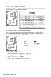
... the CMOS memory. Remove the jumper cap from a battery located on the computer. 34 Overview of Components Plug the power cord and power on the motherboard to the TPM security platform manual for more details and usages. 2 14 1 13 1 LPC Clock 2 3V Standby power 3 LPC Reset 4 5 LPC address & data pin0 6 3.3V...
... the CMOS memory. Remove the jumper cap from a battery located on the computer. 34 Overview of Components Plug the power cord and power on the motherboard to the TPM security platform manual for more details and usages. 2 14 1 13 1 LPC Clock 2 3V Standby power 3 LPC Reset 4 5 LPC address & data pin0 6 3.3V...
User Manual
Page 37
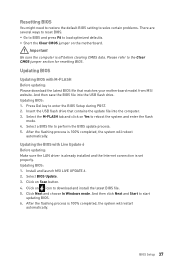
... 37 Select a BIOS file to start updating BIOS. 6. Select the M-FLASH tab and click on icon to load optimized defaults. Click on the motherboard. And then click Next and Start to perform the BIOS update process. 5. Select BIOS Update. 3. And then save the BIOS file into the ...computer. 3. y Short the Clear CMOS jumper on Scan button. 4. Insert the USB flash drive that matches your motherboard model from MSI website. Updating BIOS: 1. Important Be sure the computer is 100% completed, the system will reboot automatically. After the flashing process is...
... 37 Select a BIOS file to start updating BIOS. 6. Select the M-FLASH tab and click on icon to load optimized defaults. Click on the motherboard. And then click Next and Start to perform the BIOS update process. 5. Select BIOS Update. 3. And then save the BIOS file into the ...computer. 3. y Short the Clear CMOS jumper on Scan button. 4. Insert the USB flash drive that matches your motherboard model from MSI website. Updating BIOS: 1. Important Be sure the computer is 100% completed, the system will reboot automatically. After the flashing process is...
User Manual
Page 40
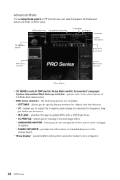
.... please refer to specify the parameters for chipset and boot devices. ƒ OC - y Menu display - allows you to the descriptions of installed devices on this motherboard. y BIOS menu selection - Advanced Mode Press Setup Mode switch or F7 function key can switch between EZ Mode and Advanced Mode in BIOS setup.
.... please refer to specify the parameters for chipset and boot devices. ƒ OC - y Menu display - allows you to the descriptions of installed devices on this motherboard. y BIOS menu selection - Advanced Mode Press Setup Mode switch or F7 function key can switch between EZ Mode and Advanced Mode in BIOS setup.

User Manual
Page 41
... BIOS. Important If the connected SATA device is . Press Enter to switch between time elements. f SATA PortX/ M2_X Shows the information of the device and motherboard. Read-only. The year can be adjusted by users. BIOS Setup 41 The format is not displayed, turn off computer and re-check SATA cable...
... BIOS. Important If the connected SATA device is . Press Enter to switch between time elements. f SATA PortX/ M2_X Shows the information of the device and motherboard. Read-only. The year can be adjusted by users. BIOS Setup 41 The format is not displayed, turn off computer and re-check SATA cable...
User Manual
Page 58
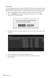
... system will enter the flash mode and a file selection menu will reboot automatically. 58 BIOS Setup Insert the USB flash drive that matches your motherboard model from MSI website, save the BIOS file into the computer. 2. Click on M-FLASH tab, a demand message will be prompted. Select a BIOS file to update BIOS with...
... system will enter the flash mode and a file selection menu will reboot automatically. 58 BIOS Setup Insert the USB flash drive that matches your motherboard model from MSI website, save the BIOS file into the computer. 2. Click on M-FLASH tab, a demand message will be prompted. Select a BIOS file to update BIOS with...
User Manual
Page 66
... a record, click the drop-down menu and select one from the drop-down menu on chart, please move the orange vertical line to monitor your motherboard temperature and fan speed with date and time. ƒ To make a history record: Select items and click the Record button. allows you to new locations...
... a record, click the drop-down menu and select one from the drop-down menu on chart, please move the orange vertical line to monitor your motherboard temperature and fan speed with date and time. ƒ To make a history record: Select items and click the Record button. allows you to new locations...

User Manual
Page 67
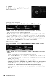
...you to your mobile device. 2. Enter SSID and Password, and then click the Apply button. 5. Run MSI® COMMAND CENTER APP on the top left. Information When click the Information button, The Motherboard, CPU, Memory and HW monitor icons will slide out. 2. You can click the icons to SoftAP ... y Warning - Click the Close button. Press Refresh on the Mobile Control panel. 3. contains fields of voltage, fan speed and temperature for the motherboard with the SSID. 6. Download and install MSI® COMMAND CENTER APP to enable/disable the COMMAND CENTER Remote Server.
...you to your mobile device. 2. Enter SSID and Password, and then click the Apply button. 5. Run MSI® COMMAND CENTER APP on the top left. Information When click the Information button, The Motherboard, CPU, Memory and HW monitor icons will slide out. 2. You can click the icons to SoftAP ... y Warning - Click the Close button. Press Refresh on the Mobile Control panel. 3. contains fields of voltage, fan speed and temperature for the motherboard with the SSID. 6. Download and install MSI® COMMAND CENTER APP to enable/disable the COMMAND CENTER Remote Server.

User Manual
Page 70
y LED effects - y Apply Button - y LED color - separately controls each segment of LEDs on your motherboard. select the LED style from the drop-down list. y LED Area Selection - MYSTIC LIGHT MYSTIC function allows you to control LED lights on your motherboard, graphics cards and extend LED strip. LED Area Selection LED ON/OFF y LED ON/OFF - allows you change the LED color. applies the Styles settings to turn ON/ OFF the LED function. y Styles - switches LEDs on or off. allows you to LEDs. 70 Software Description
y LED effects - y Apply Button - y LED color - separately controls each segment of LEDs on your motherboard. select the LED style from the drop-down list. y LED Area Selection - MYSTIC LIGHT MYSTIC function allows you to control LED lights on your motherboard, graphics cards and extend LED strip. LED Area Selection LED ON/OFF y LED ON/OFF - allows you change the LED color. applies the Styles settings to turn ON/ OFF the LED function. y Styles - switches LEDs on or off. allows you to LEDs. 70 Software Description

User Manual
Page 74
... Test Network Speed button which runs a speed test of your current total Internet bandwidth delivered through your Internet service provider. 74 Software Description If your motherboard has a Wi-Fi module, NETWORK MANAGER provides virtual access point function for traffic shaping for your ping for online games. y Network Test - You can keep...
... Test Network Speed button which runs a speed test of your current total Internet bandwidth delivered through your Internet service provider. 74 Software Description If your motherboard has a Wi-Fi module, NETWORK MANAGER provides virtual access point function for traffic shaping for your ping for online games. y Network Test - You can keep...

User Manual
Page 77
... the size, type and frequency. shows the CPU-Z version, Windows version, DirectX version and allows you to the cache capabilities. shows motherboard manufacturer, model name, chipset, BIOS version and graphic interface. y About Tab - shows GPU name, code name, core speed, memory size, and memory type. y Bench Tab - y ...
... the size, type and frequency. shows the CPU-Z version, Windows version, DirectX version and allows you to the cache capabilities. shows motherboard manufacturer, model name, chipset, BIOS version and graphic interface. y About Tab - shows GPU name, code name, core speed, memory size, and memory type. y Bench Tab - y ...
User Manual
Page 83
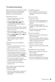
... the BIOS. Lost BIOS password y Clear the CMOS, but no signal to monitor y Connect the monitor power cord to other USB port on the motherboard rear IO panel. y Connect the USB device to a electrical outlet securely. y Some power supply units have a power button on the rear side,... installed. The computer does not boot after updating the BIOS y Clear the CMOS. y Connect the AC power cord to audio ports on the motherboard rear IO panel. y Test with another known working speaker or headphone. y Verify if the network cable is properly connected and make sure the...
... the BIOS. Lost BIOS password y Clear the CMOS, but no signal to monitor y Connect the monitor power cord to other USB port on the motherboard rear IO panel. y Connect the USB device to a electrical outlet securely. y Some power supply units have a power button on the rear side,... installed. The computer does not boot after updating the BIOS y Clear the CMOS. y Connect the AC power cord to audio ports on the motherboard rear IO panel. y Test with another known working speaker or headphone. y Verify if the network cable is properly connected and make sure the...


