User Manual
Page 13
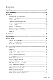
... Start ...3 Preparing Tools and Components 3 Installing a Processor 4 Installing DDR4 memory 5 Connecting the Front Panel Header 6 Installing the Motherboard 7 Installing SATA Drives 8 Installing a Graphics Card 9 Connecting Peripheral Devices 10 Connecting the Power Connectors 11 Power On...12 Specifications...15 Block Diagram ...19 Rear I/O Panel ...20 LAN Port LED Status Table 20 Audio Ports Configuration 20 Realtek HD Audio Manager 21 Overview of Components 23 CPU Socket ...25 DIMM Slots...26 PCI_E1~6: PCIe Expansion Slots 27 JAUD1: Front Audio Connector 28 SATA1~6: SATA...
... Start ...3 Preparing Tools and Components 3 Installing a Processor 4 Installing DDR4 memory 5 Connecting the Front Panel Header 6 Installing the Motherboard 7 Installing SATA Drives 8 Installing a Graphics Card 9 Connecting Peripheral Devices 10 Connecting the Power Connectors 11 Power On...12 Specifications...15 Block Diagram ...19 Rear I/O Panel ...20 LAN Port LED Status Table 20 Audio Ports Configuration 20 Realtek HD Audio Manager 21 Overview of Components 23 CPU Socket ...25 DIMM Slots...26 PCI_E1~6: PCIe Expansion Slots 27 JAUD1: Front Audio Connector 28 SATA1~6: SATA...
User Manual
Page 14
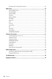
... BIOS Setup ...37 Entering BIOS Setup 37 Resetting BIOS...38 Updating BIOS...38 EZ Mode ...39 Advanced Mode ...41 SETTINGS...42 Advanced...42 Boot...48 Security ...49 Save & Exit...50 OC...51 M-FLASH ...58 OC PROFILE ...59 HARDWARE MONITOR 60 Software Description 61 Installing Windows® 7/ 8.1/ 10 61 Installing Drivers 61 Installing Utilities 61 COMMAND CENTER 62 LIVE UPDATE 6...66 M-CLOUD ...68 RAMDISK...71 Intel® Extreme Tuning Utility 72 RAID Configuration 73 Using Intel® Rapid Storage Technology Option ROM...
... BIOS Setup ...37 Entering BIOS Setup 37 Resetting BIOS...38 Updating BIOS...38 EZ Mode ...39 Advanced Mode ...41 SETTINGS...42 Advanced...42 Boot...48 Security ...49 Save & Exit...50 OC...51 M-FLASH ...58 OC PROFILE ...59 HARDWARE MONITOR 60 Software Description 61 Installing Windows® 7/ 8.1/ 10 61 Installing Drivers 61 Installing Utilities 61 COMMAND CENTER 62 LIVE UPDATE 6...66 M-CLOUD ...68 RAMDISK...71 Intel® Extreme Tuning Utility 72 RAID Configuration 73 Using Intel® Rapid Storage Technology Option ROM...
User Manual
Page 35
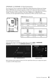
... +12V Speed Control Signal 1 SYSFAN2 Voltage Control NC Controlling the fan speed There are two ways to BIOS > HARDWARE MONITOR. PWM Mode fan connectors provide constant 12V output and adjust fan speed with speed control signal. Therefore, when you to adjust fan speed in relation to CPU temperature. BIOS > HARDWARE MONITOR COMMAND CENTER Both methods offer gradient points of Components 35 Overview of the fan speed that allow you plug a 3-pin (Non-PWM) fan to use COMMAND CENTER...
... +12V Speed Control Signal 1 SYSFAN2 Voltage Control NC Controlling the fan speed There are two ways to BIOS > HARDWARE MONITOR. PWM Mode fan connectors provide constant 12V output and adjust fan speed with speed control signal. Therefore, when you to adjust fan speed in relation to CPU temperature. BIOS > HARDWARE MONITOR COMMAND CENTER Both methods offer gradient points of Components 35 Overview of the fan speed that allow you plug a 3-pin (Non-PWM) fan to use COMMAND CENTER...
User Manual
Page 36
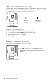
... a battery located on the computer. VGA - EZ Debug LED: Debug LED indicators These LEDs indicate the status of Components Keep Data (default) Clear CMOS/ Reset BIOS Resetting BIOS to clear the CMOS memory. DRAM - indicates CPU is not detected or fail. 36 Overview of the motherboard. indicates GPU is not detected or fail. CPU - JBAT1: Clear CMOS (Reset BIOS) Jumper There is CMOS memory onboard that is external powered from JBAT1. 4. Power off the computer and unplug the power cord. 2. Use a jumper cap...
... a battery located on the computer. VGA - EZ Debug LED: Debug LED indicators These LEDs indicate the status of Components Keep Data (default) Clear CMOS/ Reset BIOS Resetting BIOS to clear the CMOS memory. DRAM - indicates CPU is not detected or fail. 36 Overview of the motherboard. indicates GPU is not detected or fail. CPU - JBAT1: Clear CMOS (Reset BIOS) Jumper There is CMOS memory onboard that is external powered from JBAT1. 4. Power off the computer and unplug the power cord. 2. Use a jumper cap...
User Manual
Page 38
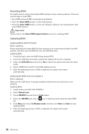
... click on Yes to the Clear CMOS jumper/ button section for the motherboard with clear CMOS button.) Important Please refer to reboot the system and enter the flash mode. 4. After the flashing process is set properly. Insert the USB flash drive that matches your motherboard model from MSI website. Click Next and choose In Windows mode. Updating BIOS Updating BIOS with Live Update 6 Before updating: Make sure the LAN driver is already installed and the internet connection is 100% completed, the...
... click on Yes to the Clear CMOS jumper/ button section for the motherboard with clear CMOS button.) Important Please refer to reboot the system and enter the flash mode. 4. After the flashing process is set properly. Insert the USB flash drive that matches your motherboard model from MSI website. Click Next and choose In Windows mode. Updating BIOS Updating BIOS with Live Update 6 Before updating: Make sure the LAN driver is already installed and the internet connection is 100% completed, the...
User Manual
Page 39
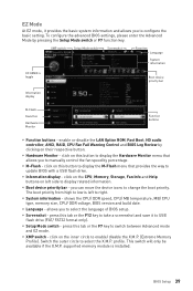
... disable the LAN Option ROM, Fast Boot, HD audio controller, AHCI, RAID, CPU Fan Fail Warning Control and BIOS Log Review by percentage. y Boot device priority bar - shows the CPU/ DDR speed, CPU/ MB temperature, MB/ CPU type, memory size, CPU/ DDR voltage, BIOS version and build date. click on the inner circle to select the X.M.P. profile. Switch the outer circle to enable/ disable the X.M.P. (Extreme Memory Profile). y M-Flash - click on this button to display the M-Flash menu that allows you to configure the basic setting. BIOS Setup 39 XMP switch Setup Mode...
... disable the LAN Option ROM, Fast Boot, HD audio controller, AHCI, RAID, CPU Fan Fail Warning Control and BIOS Log Review by percentage. y Boot device priority bar - shows the CPU/ DDR speed, CPU/ MB temperature, MB/ CPU type, memory size, CPU/ DDR voltage, BIOS version and build date. click on the inner circle to select the X.M.P. profile. Switch the outer circle to enable/ disable the X.M.P. (Extreme Memory Profile). y M-Flash - click on this button to display the M-Flash menu that allows you to configure the basic setting. BIOS Setup 39 XMP switch Setup Mode...
User Manual
Page 43
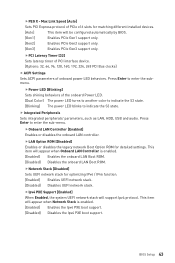
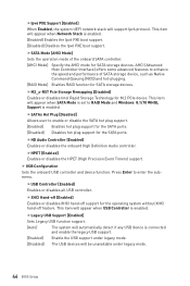
... PXE boot support. fOnboard LAN Controller [Enabled] Enables or disables the onboard LAN controller. This item will support Ipv4 protocol. Max Link Speed [Auto] Sets PCI Express protocol of the onboard Power LED. [Dual Color] The power LED turns to another color to indicate the S3 state. [Blinking] The power LED blinks to indicate the S3 state. Press Enter to enter the sub-menu. fIpv4 PXE Support [Enabled] When Enabled, the system UEFI network stack will appear when Network Stack is enabled. [Enabled] Enables the onboard LAN Boot ROM. [Disabled] Disables the onboard LAN Boot ROM. BIOS...
... PXE boot support. fOnboard LAN Controller [Enabled] Enables or disables the onboard LAN controller. This item will support Ipv4 protocol. Max Link Speed [Auto] Sets PCI Express protocol of the onboard Power LED. [Dual Color] The power LED turns to another color to indicate the S3 state. [Blinking] The power LED blinks to indicate the S3 state. Press Enter to enter the sub-menu. fIpv4 PXE Support [Enabled] When Enabled, the system UEFI network stack will appear when Network Stack is enabled. [Enabled] Enables the onboard LAN Boot ROM. [Disabled] Disables the onboard LAN Boot ROM. BIOS...
User Manual
Page 44
...the speed and performance of the onboard SATA controller. [AHCI Mode] Specify the AHCI mode for the SATA ports. fUSB Controller [Enabled] Enables or disables all USB controller. fIpv6 PXE Support [Enabled] When Enabled, the system UEFI network stack will support Ipv6 protocol. fSATA Mode [AHCI Mode] Sets the operation mode of SATA storage device, such as Native Command Queuing (NCQ) and hot-plugging. [RAID Mode] Enables RAID function for SATA storage devices. fSATAx Hot Plug [Disabled] Allows user to RAID Mode and Windows 8.1/10 WHQL Support is enabled. AHCI (Advanced...
...the speed and performance of the onboard SATA controller. [AHCI Mode] Specify the AHCI mode for the SATA ports. fUSB Controller [Enabled] Enables or disables all USB controller. fIpv6 PXE Support [Enabled] When Enabled, the system UEFI network stack will support Ipv6 protocol. fSATA Mode [AHCI Mode] Sets the operation mode of SATA storage device, such as Native Command Queuing (NCQ) and hot-plugging. [RAID Mode] Enables RAID function for SATA storage devices. fSATAx Hot Plug [Disabled] Allows user to RAID Mode and Windows 8.1/10 WHQL Support is enabled. AHCI (Advanced...
User Manual
Page 45
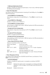
... Port mode + Enhanced Parallel Port-1.9/ 1.7 mode. Press Enter to Auto, BIOS will optimize the USB speed automatically. Press Enter to Auto, BIOS will not support S4 & S5 wake up by USB and PCIe devices. [Disabled] Disables this function. If set it manually. f Super IO Configuration Sets system Super I/O chip parameters including LPT and COM ports. fSerial (COM) Port 0 Settings [Auto] Sets serial port x (COM). f Power Management Setup Sets system Power Management of EuP2013 and AC Power Loss behaviors. fEuP 2013 [Disabled] Enables or disables the system power...
... Port mode + Enhanced Parallel Port-1.9/ 1.7 mode. Press Enter to Auto, BIOS will optimize the USB speed automatically. Press Enter to Auto, BIOS will not support S4 & S5 wake up by USB and PCIe devices. [Disabled] Disables this function. If set it manually. f Super IO Configuration Sets system Super I/O chip parameters including LPT and COM ports. fSerial (COM) Port 0 Settings [Auto] Sets serial port x (COM). f Power Management Setup Sets system Power Management of EuP2013 and AC Power Loss behaviors. fEuP 2013 [Disabled] Enables or disables the system power...
User Manual
Page 46
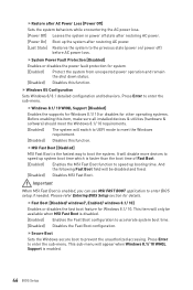
... WHQL Support is disabled. [Enabled] Enables the Fast Boot configuration to meet the Windows 8.1/ 10 requirements. [Enabled] The system will switch to UEFI mode to accelerate system boot time. [Disabled] Disables the Fast Boot configuration. fSystem Power Fault Protection [Disabled] Enables or disables the power fault protection for other operating systems. Before enabling this item, make sure all installed devices & utilities (hardware & software) should meet the Windows requirement. [Disabled] Disables this function. Press Enter to the previous state (power on/ power off...
... WHQL Support is disabled. [Enabled] Enables the Fast Boot configuration to meet the Windows 8.1/ 10 requirements. [Enabled] The system will switch to UEFI mode to accelerate system boot time. [Disabled] Disables the Fast Boot configuration. fSystem Power Fault Protection [Disabled] Enables or disables the power fault protection for other operating systems. Before enabling this item, make sure all installed devices & utilities (hardware & software) should meet the Windows requirement. [Disabled] Disables this function. Press Enter to the previous state (power on/ power off...
User Manual
Page 47
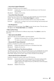
... will automatically resume (boot up event by BIOS or operating system. [BIOS] Activates the following items, set to [Enabled], the system will automatically load the secure keys from the power saving modes when activity or input signal of month) Alarm/ Time (hh:mm:ss) Alarm Sets RTC alarm date/ Time. fDate (of PCI-E device is set wake up behaviors for different sleep modes. Please use the + and...
... will automatically resume (boot up event by BIOS or operating system. [BIOS] Activates the following items, set to [Enabled], the system will automatically load the secure keys from the power saving modes when activity or input signal of month) Alarm/ Time (hh:mm:ss) Alarm Sets RTC alarm date/ Time. fDate (of PCI-E device is set wake up behaviors for different sleep modes. Please use the + and...
User Manual
Page 50
... to enter the sub-menu. Once the password is being disabled. This function is opened . f Save Changes Save current changes. A message will record and issue a warning message. [Reset] Clear the warning message. f Restore Defaults Restore or load all changes and reboot the system. To clear a set to the previous values. fDevice select [Auto] Selects TPM 1.2 or TPM 2.0 for the chassis equips a chassis intrusion switch. [Enabled] Once the chassis is...
... to enter the sub-menu. Once the password is being disabled. This function is opened . f Save Changes Save current changes. A message will record and issue a warning message. [Reset] Clear the warning message. f Restore Defaults Restore or load all changes and reboot the system. To clear a set to the previous values. fDevice select [Auto] Selects TPM 1.2 or TPM 2.0 for the chassis equips a chassis intrusion switch. [Enabled] Once the chassis is...

User Manual
Page 52
... adjust CPU voltage and core frequency dynamically. Read-only. This item appears when a CPU that overclocking behavior and stability is installed. f Ring Ratio [Auto] Sets the ring ratio. f Adjusted Ring Frequency Shows the adjusted Ring frequency. fEIST [Enabled]* Enables or disables the Enhanced Intel® SpeedStep Technology. [Enabled] Enables the EIST to boost CPU performance automatically above rated specifications when system request the highest performance state. [Disabled] Disables this function. key to...
... adjust CPU voltage and core frequency dynamically. Read-only. This item appears when a CPU that overclocking behavior and stability is installed. f Ring Ratio [Auto] Sets the ring ratio. f Adjusted Ring Frequency Shows the adjusted Ring frequency. fEIST [Enabled]* Enables or disables the Enhanced Intel® SpeedStep Technology. [Enabled] Enables the EIST to boost CPU performance automatically above rated specifications when system request the highest performance state. [Disabled] Disables this function. key to...
User Manual
Page 53
f DRAM Reference Clock [Auto]* Sets the DRAM reference clock. f Adjusted DRAM Frequency Shows the adjusted DRAM frequency. f DRAM Timing Mode [Link] Selects the memory timing mode. [Link] Allows user to configure the DRAM timing for all memory channel. [UnLink] Allows user to load the default settings.) f Memory Fast Boot [Auto] * Enables or disables the initiation and training for memory. The system may become unstable or unbootable after changing memory timing. The valid value range depends on the installed CPU. Please note the overclocking behavior is...
f DRAM Reference Clock [Auto]* Sets the DRAM reference clock. f Adjusted DRAM Frequency Shows the adjusted DRAM frequency. f DRAM Timing Mode [Link] Selects the memory timing mode. [Link] Allows user to configure the DRAM timing for all memory channel. [UnLink] Allows user to load the default settings.) f Memory Fast Boot [Auto] * Enables or disables the initiation and training for memory. The system may become unstable or unbootable after changing memory timing. The valid value range depends on the installed CPU. Please note the overclocking behavior is...
User Manual
Page 54
... been replaced. [Enabled] The system will set these voltages automatically or you can also access this information menu at any time by pressing [F5]. 54 BIOS Setup f CPU Memory Changed Detect [Enabled]* Enables or disables the system to issue a warning message during boot and then you have to enter the sub-menu. The sub-menu shows the key features of installed memory. This sub-menu displays all the settings and timings of installed CPU. If set to Auto, BIOS...
... been replaced. [Enabled] The system will set these voltages automatically or you can also access this information menu at any time by pressing [F5]. 54 BIOS Setup f CPU Memory Changed Detect [Enabled]* Enables or disables the system to issue a warning message during boot and then you have to enter the sub-menu. The sub-menu shows the key features of installed memory. This sub-menu displays all the settings and timings of installed CPU. If set to Auto, BIOS...
User Manual
Page 56
... a processor power management technology defined by ACPI. [Auto] This setting will be configured automatically by BIOS. [Enabled] Detects the idle state of C-state depend on the installed CPU. fCFG Lock [Enabled] Lock or un-lock the MSR 0xE2[15], CFG lock bit. [Enabled] Locks the CFG lock bit. [Disabled] Un-locks the CFG lock bit. 56 BIOS Setup fPackage C State limit [Auto] This item allows you to reduce the CPU frequency and voltage...
... a processor power management technology defined by ACPI. [Auto] This setting will be configured automatically by BIOS. [Enabled] Detects the idle state of C-state depend on the installed CPU. fCFG Lock [Enabled] Lock or un-lock the MSR 0xE2[15], CFG lock bit. [Enabled] Locks the CFG lock bit. [Disabled] Un-locks the CFG lock bit. 56 BIOS Setup fPackage C State limit [Auto] This item allows you to reduce the CPU frequency and voltage...
User Manual
Page 58
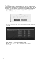
... and enter the flash mode. 3. Click on M-FLASH tab, a demand message will be prompted. Please download the latest BIOS file that contains the update file into your USB flash drive. Click on Yes to update BIOS. 1. Select a BIOS file to update BIOS with a USB flash drive. Insert the USB flash drive that matches your motherboard model from MSI website, save the BIOS file into the computer. 2. M-FLASH M-FLASH provides the way to perform the BIOS update process. 5. The system will enter the flash mode and a file selection menu...
... and enter the flash mode. 3. Click on M-FLASH tab, a demand message will be prompted. Please download the latest BIOS file that contains the update file into your USB flash drive. Click on Yes to update BIOS. 1. Select a BIOS file to update BIOS with a USB flash drive. Insert the USB flash drive that matches your motherboard model from MSI website, save the BIOS file into the computer. 2. M-FLASH M-FLASH provides the way to perform the BIOS update process. 5. The system will enter the flash mode and a file selection menu...
User Manual
Page 61
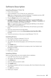
... USB port when installing Windows® 7. 5. Press any key when screen shows Press any key to enabled, save changes and restart. Insert MSI® Driver Disc into your optical drive from CD or DVD... For Windows® 7, access the BIOS menu SETTINGS > Advanced > Windows OS Configuration > Windows 7 Installation and set the item to boot from the Boot Menu. 7. The installer will then be in Windows® 7/ 8.1/ 10. 2. Press F11 key during the Windows® 7 installation process, USB optical drives or USB flash drives are not supported. 3. The installer...
... USB port when installing Windows® 7. 5. Press any key when screen shows Press any key to enabled, save changes and restart. Insert MSI® Driver Disc into your optical drive from CD or DVD... For Windows® 7, access the BIOS menu SETTINGS > Advanced > Windows OS Configuration > Windows 7 Installation and set the item to boot from the Boot Menu. 7. The installer will then be in Windows® 7/ 8.1/ 10. 2. Press F11 key during the Windows® 7 installation process, USB optical drives or USB flash drives are not supported. 3. The installer...
User Manual
Page 78
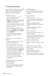
... network y Make sure the network chipset driver has been installed. y Select different inputs on . y If 1 long 2 short beeps are heard, remove all customized settings in the BIOS. Lost BIOS password y Clear the CMOS, but no audio y Adjust the volume. y Remove secondary speakers/ headphones, HDMI cables, USB audio devices. There is connected to JFP1 pin header properly. y Verify your router. y Connect the AC power cord to audio ports on the rear side, make sure the button is properly connected and make sure the LAN port LEDs...
... network y Make sure the network chipset driver has been installed. y Select different inputs on . y If 1 long 2 short beeps are heard, remove all customized settings in the BIOS. Lost BIOS password y Clear the CMOS, but no audio y Adjust the volume. y Remove secondary speakers/ headphones, HDMI cables, USB audio devices. There is connected to JFP1 pin header properly. y Verify your router. y Connect the AC power cord to audio ports on the rear side, make sure the button is properly connected and make sure the LAN port LEDs...
User Manual
Page 82
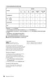
... names used in this document, but no guarantee is the intellectual property of its contents. The material in this manual are the properties of purchase or local distributor. Revision History Version 1.1, 2015/10, release for Z170A SLI. 82 Regulatory Notices Alternatively, please try the following help resources for technical guide, BIOS updates, driver updates, and other information: http://www.msi.com...
... names used in this document, but no guarantee is the intellectual property of its contents. The material in this manual are the properties of purchase or local distributor. Revision History Version 1.1, 2015/10, release for Z170A SLI. 82 Regulatory Notices Alternatively, please try the following help resources for technical guide, BIOS updates, driver updates, and other information: http://www.msi.com...


