User Manual
Page 1
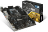
Check to make sure your motherboard box contains the following items. If something is missing, contact your dealer as soon as possible. Unpacking Thank you for buying the MSI® Z170-A PRO motherboard. Motherboard Drivers & Utilities Disc Motherboard User Guide I/O Shield SATA Cable x6 Unpacking 1
Check to make sure your motherboard box contains the following items. If something is missing, contact your dealer as soon as possible. Unpacking Thank you for buying the MSI® Z170-A PRO motherboard. Motherboard Drivers & Utilities Disc Motherboard User Guide I/O Shield SATA Cable x6 Unpacking 1

User Manual
Page 2
... sensitive components. ●● It is recommended to wear an electrostatic discharge (ESD) wrist strap when handling the motherboard to ensure successful computer assembly. ●● Ensure that all components are securely connected. This could cause permanent damage...computer component. ●● Keep this user guide for future reference. ●● Keep this motherboard away from electrostatic discharge (ESD). Loose connections may damage the motherboard. 2 Safety Information Safety Information ●● The components included in this package are prone to ...
... sensitive components. ●● It is recommended to wear an electrostatic discharge (ESD) wrist strap when handling the motherboard to ensure successful computer assembly. ●● Ensure that all components are securely connected. This could cause permanent damage...computer component. ●● Keep this user guide for future reference. ●● Keep this motherboard away from electrostatic discharge (ESD). Loose connections may damage the motherboard. 2 Safety Information Safety Information ●● The components included in this package are prone to ...

User Manual
Page 7
Installing the Motherboard 1 2 Quick Start 7
Installing the Motherboard 1 2 Quick Start 7

User Manual
Page 13
Contents Unpacking...1 Safety Information...2 Quick Start...3 Preparing Tools and Components 3 Installing a Processor 4 Installing DDR4 memory 5 Connecting the Front Panel Header 6 Installing the Motherboard 7 Installing SATA Drives 8 Installing a Graphics Card 9 Connecting Peripheral Devices 10 Connecting the Power Connectors 11 Power On...12 Specifications...15 Block Diagram ...19 Rear I/O Panel......
Contents Unpacking...1 Safety Information...2 Quick Start...3 Preparing Tools and Components 3 Installing a Processor 4 Installing DDR4 memory 5 Connecting the Front Panel Header 6 Installing the Motherboard 7 Installing SATA Drives 8 Installing a Graphics Card 9 Connecting Peripheral Devices 10 Connecting the Power Connectors 11 Power On...12 Specifications...15 Block Diagram ...19 Rear I/O Panel......
User Manual
Page 25
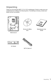
...protect the CPU socket pins by inadequate operation beyond product specifications is designed to support overclocking. MSI will deal with Return Merchandise Authorization (RMA) requests if only the motherboard comes with the CPU before installing or removing the CPU. ●● Please retain the ...CPU protective cap after installing the processor. MSI® does not guarantee the damages or risks caused by ...
...protect the CPU socket pins by inadequate operation beyond product specifications is designed to support overclocking. MSI will deal with Return Merchandise Authorization (RMA) requests if only the motherboard comes with the CPU before installing or removing the CPU. ●● Please retain the ...CPU protective cap after installing the processor. MSI® does not guarantee the damages or risks caused by ...

User Manual
Page 26
... the CPU. ●● Please note that you to install 64-bit Windows OS if you want to install more than 4GB memory on the motherboard. ●● Some memory may operate at a lower frequency than the amount of installed. ●● Based on installed CPU and devices when overclocking. 26...
... the CPU. ●● Please note that you to install 64-bit Windows OS if you want to install more than 4GB memory on the motherboard. ●● Some memory may operate at a lower frequency than the amount of installed. ●● Based on installed CPU and devices when overclocking. 26...

User Manual
Page 28
SATA3 SATA4 SATA5 SATA1 SATA6 SATA2 SE1_21-SE2_65: SATAe Connectors These connectors are SATA 6Gb/s interface ports. Each SATAe connector can connect to the motherboard for space saving purposes. 28 Overview of the cable. SATA6 SATA5 SATA1 SATA2 SE2_65 (SATA_EX2) SE1_21 (SATA_EX1) Important ●● Please do not fold the ...
SATA3 SATA4 SATA5 SATA1 SATA6 SATA2 SE1_21-SE2_65: SATAe Connectors These connectors are SATA 6Gb/s interface ports. Each SATAe connector can connect to the motherboard for space saving purposes. 28 Overview of the cable. SATA6 SATA5 SATA1 SATA2 SE2_65 (SATA_EX2) SE1_21 (SATA_EX1) Important ●● Please do not fold the ...

User Manual
Page 31
Overview of the motherboard. JPWR1~2: Power Connectors These connectors allow you to connect an ATX power supply. 8 4 5 1 JPWR2 1 Ground 5 2 Ground 6 3 Ground 7 4 Ground 8 +12V +12V +12V +12V 1 +3.3V 13 2 +3.3V ...
Overview of the motherboard. JPWR1~2: Power Connectors These connectors allow you to connect an ATX power supply. 8 4 5 1 JPWR2 1 Ground 5 2 Ground 6 3 Ground 7 4 Ground 8 +12V +12V +12V +12V 1 +3.3V 13 2 +3.3V ...

User Manual
Page 33
... of Components 33 http://youtu.be/FCyvjr5NbOw Important When the Charging mode is enabled, the Charge Port data syncing will need to install the MSI® SUPER CHARGER application to turn ON/OFF the Charging mode. However, when you boot the computer into Windows®, you to charge... the smartphone with SuperCharge. The Charger Port is hardware controlled by motherboard chip, it can increase USB power output for fast charging your device in suspend, hibernate state or even shutdown states. Charger Port JUSB3 The...
... of Components 33 http://youtu.be/FCyvjr5NbOw Important When the Charging mode is enabled, the Charge Port data syncing will need to install the MSI® SUPER CHARGER application to turn ON/OFF the Charging mode. However, when you boot the computer into Windows®, you to charge... the smartphone with SuperCharge. The Charger Port is hardware controlled by motherboard chip, it can increase USB power output for fast charging your device in suspend, hibernate state or even shutdown states. Charger Port JUSB3 The...

User Manual
Page 36
... the power cord 2. Remove the jumper cap from a battery located on the computer. 36 Overview of Components Plug the power cord and power on the motherboard to save system configuration data. Use a jumper cap to the TPM security platform manual for more details and usages. 2 14 1 13 1 LPC Clock 2 3V Standby...
... the power cord 2. Remove the jumper cap from a battery located on the computer. 36 Overview of Components Plug the power cord and power on the motherboard to save system configuration data. Use a jumper cap to the TPM security platform manual for more details and usages. 2 14 1 13 1 LPC Clock 2 3V Standby...

User Manual
Page 37
... then press the Enter key to connect the chassis intrusion switch cable. Set Chassis Intrusion to BIOS > Settings > Security > Chassis Intrusion Configuration. 2. Overview of the motherboard. JCI1: Chassis Intrusion Connector This connector allows you to select Yes. 6. Resetting the chassis intrusion warning 1.
... then press the Enter key to connect the chassis intrusion switch cable. Set Chassis Intrusion to BIOS > Settings > Security > Chassis Intrusion Configuration. 2. Overview of the motherboard. JCI1: Chassis Intrusion Connector This connector allows you to select Yes. 6. Resetting the chassis intrusion warning 1.
User Manual
Page 39
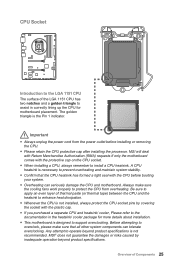
...And then click Next and Start to download and install the latest BIOS 5. Updating BIOS: 1. Insert the USB flash drive that matches your motherboard model from MSI website. Select Manual scan. 3. Click Next and choose In Windows mode. Press Del key to perform the BIOS update process. 5. Check MB...system and enter the flash mode. 4. Select the M-FLASH tab and click on Yes to the Clear CMOS jumper/ button section for the motherboard with M-FLASH Before updating: Please download the latest BIOS file that contains the update file into the USB flash drive. Updating BIOS: 1. ...
...And then click Next and Start to download and install the latest BIOS 5. Updating BIOS: 1. Insert the USB flash drive that matches your motherboard model from MSI website. Select Manual scan. 3. Click Next and choose In Windows mode. Press Del key to perform the BIOS update process. 5. Check MB...system and enter the flash mode. 4. Select the M-FLASH tab and click on Yes to the Clear CMOS jumper/ button section for the motherboard with M-FLASH Before updating: Please download the latest BIOS file that contains the update file into the USB flash drive. Updating BIOS: 1. ...

User Manual
Page 42
... EZ Mode Overview section. ●● BIOS menu selection - the following options are available: ▶▶SETTINGS - provides the information of installed devices on this motherboard. ●● Menu display - Advanced Mode Press Setup Mode switch or F7 function key can switch between EZ Mode and Advanced Mode in BIOS setup...
... EZ Mode Overview section. ●● BIOS menu selection - the following options are available: ▶▶SETTINGS - provides the information of installed devices on this motherboard. ●● Menu display - Advanced Mode Press Setup Mode switch or F7 function key can switch between EZ Mode and Advanced Mode in BIOS setup...

User Manual
Page 43
Read-only. The time format is not displayed, turn off computer and re-check SATA cable and power cable connections of the device and motherboard. ▶▶System Information Shows detailed system information, including CPU type, BIOS version, and Memory (read only). ▶▶DMI Information Shows system information, desktop ...
Read-only. The time format is not displayed, turn off computer and re-check SATA cable and power cable connections of the device and motherboard. ▶▶System Information Shows detailed system information, including CPU type, BIOS version, and Memory (read only). ▶▶DMI Information Shows system information, desktop ...
User Manual
Page 52
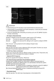
...; Overclocking is not guaranteed, and if done improperly, it could void your warranty or severely damage your hardware. ●● If you are unfamiliar with MSI optimized overclocking profile. [By BIOS Options] OC GENIE function is enabled by clicking the virtual OC GENIE 4 toggle at the top left corner of BIOS... These items only appear when a CPU that is installed. ▶▶Adjusted CPU Frequency Shows the adjusted CPU frequency. The valid value range depends on motherboard.
...; Overclocking is not guaranteed, and if done improperly, it could void your warranty or severely damage your hardware. ●● If you are unfamiliar with MSI optimized overclocking profile. [By BIOS Options] OC GENIE function is enabled by clicking the virtual OC GENIE 4 toggle at the top left corner of BIOS... These items only appear when a CPU that is installed. ▶▶Adjusted CPU Frequency Shows the adjusted CPU frequency. The valid value range depends on motherboard.

User Manual
Page 58
... M-FLASH M-FLASH provides the way to reboot and enter the flash mode. 3. Please download the latest BIOS file that contains the update file into your motherboard model from MSI website, save the BIOS file into the computer. 2.
... M-FLASH M-FLASH provides the way to reboot and enter the flash mode. 3. Please download the latest BIOS file that contains the update file into your motherboard model from MSI website, save the BIOS file into the computer. 2.

User Manual
Page 60
... Buttons Voltage display ▶▶Current Temperature & Speed information Shows the current CPU temperature, system temperature and fans' speeds. ▶▶Fan control field This motherboard provides a fan speed control feature call Smart Fan.
... Buttons Voltage display ▶▶Current Temperature & Speed information Shows the current CPU temperature, system temperature and fans' speeds. ▶▶Fan control field This motherboard provides a fan speed control feature call Smart Fan.

User Manual
Page 64
... the drop-down menu. ▶▶To load a record, click the drop-down menu on chart, please move the orange vertical line to monitor your motherboard temperature and fan speed with date and time. ▶▶To make a history record: Select items and click the Record button.
... the drop-down menu. ▶▶To load a record, click the drop-down menu on chart, please move the orange vertical line to monitor your motherboard temperature and fan speed with date and time. ▶▶To make a history record: Select items and click the Record button.

User Manual
Page 65
...) 1. Click the Spanner icon on the top left. ●● To arrange gadgets: 1. Information When click the Information button, The Motherboard, CPU, Memory and HW monitor icons will pop-up. ●● Mobile Control - contains fields of voltage, fan speed and temperature for the... motherboard with the SSID. 6. Select the check box next to monitor the system status. Download and install MSI® COMMAND CENTER APP to open the related information. You can click the icons to your...
...) 1. Click the Spanner icon on the top left. ●● To arrange gadgets: 1. Information When click the Information button, The Motherboard, CPU, Memory and HW monitor icons will pop-up. ●● Mobile Control - contains fields of voltage, fan speed and temperature for the... motherboard with the SSID. 6. Select the check box next to monitor the system status. Download and install MSI® COMMAND CENTER APP to open the related information. You can click the icons to your...

User Manual
Page 66
...frequency that LIVE UPDATE 6 remind you to select files to update your system with LIVE UPDATE 6. LIVE UPDATE 6 LIVE UPDATE 6 is an application for the MSI® system to update. ●● System Information - displays the information of the item ●● History - You can also read the relevant ...Scanned Date There are Live Update, History, Setting and System Information tabs at first. You can click the tab to know the models of motherboard and graphics cards. When you launch LIVE UPDATE 6, you don't need to switch the control panel. ●● Live Update -
...frequency that LIVE UPDATE 6 remind you to select files to update your system with LIVE UPDATE 6. LIVE UPDATE 6 LIVE UPDATE 6 is an application for the MSI® system to update. ●● System Information - displays the information of the item ●● History - You can also read the relevant ...Scanned Date There are Live Update, History, Setting and System Information tabs at first. You can click the tab to know the models of motherboard and graphics cards. When you launch LIVE UPDATE 6, you don't need to switch the control panel. ●● Live Update -


