
User Guide
Page 4
... experienced radio/television technician for compliance could void the user's authority to comply with the emission limits. Notice 2 Shielded interface cables and A.C. Micro-Star International MS-7522 This device complies with the instructions, may cause undesired operation. This equipment generates, uses and can be used in order to operate the equipment. iv...
... experienced radio/television technician for compliance could void the user's authority to comply with the emission limits. Notice 2 Shielded interface cables and A.C. Micro-Star International MS-7522 This device complies with the instructions, may cause undesired operation. This equipment generates, uses and can be used in order to operate the equipment. iv...
User Guide
Page 10
The X58 Platinum mainboard is based on Intel® X58 & ICH10R chipsets for choosing the X58 Platinum (MS-7522 v1.X) ATX mainboard. Getting Started Chapter 1 Getting Started Thank you for optimal system efficiency. Designed to fit the advanced Intel® i7 LGA1366 processor, the X58 Platinum delivers a high performance and professional desktop platform solution. 1-1
The X58 Platinum mainboard is based on Intel® X58 & ICH10R chipsets for choosing the X58 Platinum (MS-7522 v1.X) ATX mainboard. Getting Started Chapter 1 Getting Started Thank you for optimal system efficiency. Designed to fit the advanced Intel® i7 LGA1366 processor, the X58 Platinum delivers a high performance and professional desktop platform solution. 1-1
User Guide
Page 11
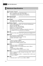
... with Azalia 1.0 Spec IDE - 1 IDE port by Realtek® AL888 - Supports Ultra DMA 66/100/133 mode - m si . c om . m si. p hp?func =t est report ) LAN - MS-7522 Mainboard Mainboard Specifications Processor Support - Supports 2 PCIE LAN 10/100/1000 Fast Ethernet by JMicron JMB381 1-2 Intel® i7 processors in the LGA1366 package (For... Bridge: Intel® ICH10R chipset Memory Support - 6 DDR3 DIMMs support DDR3 1333/ 1066/ 800 SDRAM speed (Memory size 24GB Max) - t w / i ndex. North Bridge: Intel® X58 chipset -
... with Azalia 1.0 Spec IDE - 1 IDE port by Realtek® AL888 - Supports Ultra DMA 66/100/133 mode - m si . c om . m si. p hp?func =t est report ) LAN - MS-7522 Mainboard Mainboard Specifications Processor Support - Supports 2 PCIE LAN 10/100/1000 Fast Ethernet by JMicron JMB381 1-2 Intel® i7 processors in the LGA1366 package (For... Bridge: Intel® ICH10R chipset Memory Support - 6 DDR3 DIMMs support DDR3 1333/ 1066/ 800 SDRAM speed (Memory size 24GB Max) - t w / i ndex. North Bridge: Intel® X58 chipset -

User Guide
Page 13
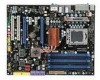
JPWR1 MS-7522 Mainboard Mainboard Layout Top : mouse JPWR2 Bo tt om: keyboard CP UFA N Top: USB ports Bot to m: 1394 port Optical S/PDIF-Out eSATA ...: USB ports Top: LAN Jack Bottom: USB ports T:L in e-I n M:Line-Out B:Mic T:RS -Out M:CS-Out B:SS-Out PCI _E1 PCI _E2 Intel X58 SYSFA N2 JSPI PCI _E3 PCI _E4 PCI _E5 PCI 1 BAT T + PCI 2 JAU D1 JC D1 ON J1394_1 123 POWER1 CPU_CLK1 JUSB2 RESET1 DIMM_A1 DIMM_A0...ICH10R JCI1 SY SFAN1 SYS FAN3 JSMB1 SATA1 _3 SATA2 _4 SATA8 SATA7 SATA5_ 6 IDE1 DLED2 2D -LED JUSB2 JC OM1 JTPM1 JFP2 JFP1 X58 Platinum (MS-7522 v1.X) ATX Mainboard 1-4
JPWR1 MS-7522 Mainboard Mainboard Layout Top : mouse JPWR2 Bo tt om: keyboard CP UFA N Top: USB ports Bot to m: 1394 port Optical S/PDIF-Out eSATA ...: USB ports Top: LAN Jack Bottom: USB ports T:L in e-I n M:Line-Out B:Mic T:RS -Out M:CS-Out B:SS-Out PCI _E1 PCI _E2 Intel X58 SYSFA N2 JSPI PCI _E3 PCI _E4 PCI _E5 PCI 1 BAT T + PCI 2 JAU D1 JC D1 ON J1394_1 123 POWER1 CPU_CLK1 JUSB2 RESET1 DIMM_A1 DIMM_A0...ICH10R JCI1 SY SFAN1 SYS FAN3 JSMB1 SATA1 _3 SATA2 _4 SATA8 SATA7 SATA5_ 6 IDE1 DLED2 2D -LED JUSB2 JC OM1 JTPM1 JFP2 JFP1 X58 Platinum (MS-7522 v1.X) ATX Mainboard 1-4

User Guide
Page 18
... install the CPU & cooler correctly. W rong installation will cause the damage of the CPU base. Be sure to grasp on the top to prevent overheating. MS-7522 Mainboard CPU & Cooler Installation W hen you install CPU, always cover it to protect the contack from the lever hinge side (as the arrow shows). 4. Open...
... install the CPU & cooler correctly. W rong installation will cause the damage of the CPU base. Be sure to grasp on the top to prevent overheating. MS-7522 Mainboard CPU & Cooler Installation W hen you install CPU, always cover it to protect the contack from the lever hinge side (as the arrow shows). 4. Open...

User Guide
Page 20
... clips get wedged into the holes of the CPU/ cooler installation only. Align the holes on the model you purchase. 2-6 Mainboard locking switch Hook Important 1. MS-7522 Mainboard 9. Read the CPU status in this section are correctly inserted. The appearance of your CPU socket pin with the heatsink.
... clips get wedged into the holes of the CPU/ cooler installation only. Align the holes on the model you purchase. 2-6 Mainboard locking switch Hook Important 1. MS-7522 Mainboard 9. Read the CPU status in this section are correctly inserted. The appearance of your CPU socket pin with the heatsink.
User Guide
Page 22
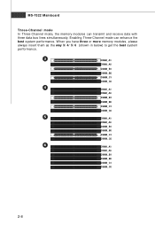
MS-7522 Mainboard Three-Channel mode In Three-Channel mode, the memory modules can enhance the best system performance. Enabling Three-Channel mode can transmit and receive ...
MS-7522 Mainboard Three-Channel mode In Three-Channel mode, the memory modules can enhance the best system performance. Enabling Three-Channel mode can transmit and receive ...
User Guide
Page 24
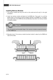
... deeply inserted in the right orientation. 2. Manually check if the memory module has been locked in the DIMM slot. 3. The plastic clip at the sides. MS-7522 Mainboard Installing Memory Modules 1. Important You can barely see the golden finger if the memory module is properly inserted in place by the DIMM slot...
... deeply inserted in the right orientation. 2. Manually check if the memory module has been locked in the DIMM slot. 3. The plastic clip at the sides. MS-7522 Mainboard Installing Memory Modules 1. Important You can barely see the golden finger if the memory module is properly inserted in place by the DIMM slot...
User Guide
Page 26
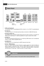
... devices. Clear CMOS Button There is a CMOS RAM on board that you want to clear the system configuration, use the button to clear the data. MS-7522 Mainboard Back Panel Mouse Keyboard USB Ports LAN LAN Line-In RS-Out Line-Out CS-Out 1394 Port eSATA Ports USB Ports USB Ports...
... devices. Clear CMOS Button There is a CMOS RAM on board that you want to clear the system configuration, use the button to clear the data. MS-7522 Mainboard Back Panel Mouse Keyboard USB Ports LAN LAN Line-In RS-Out Line-Out CS-Out 1394 Port eSATA Ports USB Ports USB Ports...
User Guide
Page 28
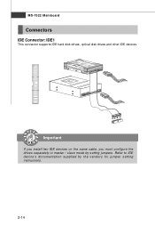
Important If you install two IDE devices on the same cable, you must configure the drives separately to IDE device's documentation supplied by setting jumpers. Refer to master / slave mode by the vendors for jumper setting instructions. 2-14 MS-7522 Mainboard Connectors IDE Connector: IDE1 This connector supports IDE hard disk drives, optical disk drives and other IDE devices.
Important If you install two IDE devices on the same cable, you must configure the drives separately to IDE device's documentation supplied by setting jumpers. Refer to master / slave mode by the vendors for jumper setting instructions. 2-14 MS-7522 Mainboard Connectors IDE Connector: IDE1 This connector supports IDE hard disk drives, optical disk drives and other IDE devices.

User Guide
Page 30
If the mainboard has a System Hardware Monitor chipset on-board, you to the actual CPU temperature. 3. SYSFAN1~3 support fan control, too. MS-7522 Mainboard Fan Power Connectors: CPUFAN, SYSFAN1~5 The fan power connectors support system cooling fan with 3 or 4 pins power connector are both available for CPUFAN1. 4. the ...
If the mainboard has a System Hardware Monitor chipset on-board, you to the actual CPU temperature. 3. SYSFAN1~3 support fan control, too. MS-7522 Mainboard Fan Power Connectors: CPUFAN, SYSFAN1~5 The fan power connectors support system cooling fan with 3 or 4 pins power connector are both available for CPUFAN1. 4. the ...
User Guide
Page 32
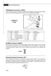
... quick guide for more details and usages. 12 11 JDLED1 21 Chassis Intrusion Connector: JCI1 This connector connects to a TPM (Trusted Platform Module) module (optional). MS-7522 Mainboard TPM Module Connector: JTPM1 This connector connects to the chassis intrusion switch cable. Please refer to the TPM security platform manual for more details...
... quick guide for more details and usages. 12 11 JDLED1 21 Chassis Intrusion Connector: JCI1 This connector connects to a TPM (Trusted Platform Module) module (optional). MS-7522 Mainboard TPM Module Connector: JTPM1 This connector connects to the chassis intrusion switch cable. Please refer to the TPM security platform manual for more details...

User Guide
Page 34
... panel JACK2 S/PDIF-Out Connector: JSP1 This connector is compliant with Intel® Front Panel I/O Connectivity Design Guide. JSP1 GND SPDIF 2-20 S/PDIF Bracket (optional) MS-7522 Mainboard CD-In Connector: JCD1 This connector is provided for digital audio transmission.
... panel JACK2 S/PDIF-Out Connector: JSP1 This connector is compliant with Intel® Front Panel I/O Connectivity Design Guide. JSP1 GND SPDIF 2-20 S/PDIF Bracket (optional) MS-7522 Mainboard CD-In Connector: JCD1 This connector is provided for digital audio transmission.

User Guide
Page 36
... PCI Express x1 Slots support up to PCI Express 1.0 x1 speed (PCI_E3 & PCI_E4) Important The mainboard supports ATI CrossFireXTM technology with two PCIEx16 slots 2-22 MS-7522 Mainboard Slots PCI (Peripheral Component Interconnect) Express Slot The PCI Express slot supports the PCI Express interface expansion card. The PCI Express 2.0 x1 supports up...
... PCI Express x1 Slots support up to PCI Express 1.0 x1 speed (PCI_E3 & PCI_E4) Important The mainboard supports ATI CrossFireXTM technology with two PCIEx16 slots 2-22 MS-7522 Mainboard Slots PCI (Peripheral Component Interconnect) Express Slot The PCI Express slot supports the PCI Express interface expansion card. The PCI Express 2.0 x1 supports up...
User Guide
Page 38
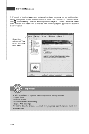
... the desktop. Important A ATI CrossFireX™ system has four possible display modes: • SuperTiling • Scissor Mode • Alternate Frame Rendering • Super Anti-aliasing. MS-7522 Mainboard 3.W hen all of the hardware and software has been properly set up and installed, reboot the system. There is a setting in Catalyst™ Control...
... the desktop. Important A ATI CrossFireX™ system has four possible display modes: • SuperTiling • Scissor Mode • Alternate Frame Rendering • Super Anti-aliasing. MS-7522 Mainboard 3.W hen all of the hardware and software has been properly set up and installed, reboot the system. There is a setting in Catalyst™ Control...
User Guide
Page 40
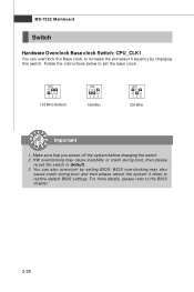
... to default. 3. Follow the instructions below to the BIOS chapter. 2-26 For more details, please refer to set the switch to restore default BIOS settings. MS-7522 Mainboard Switch Hardware Overclock Base clock Switch: CPU_CLK1 You can also overclock by changing this switch. Make sure that you power off the system before...
... to default. 3. Follow the instructions below to the BIOS chapter. 2-26 For more details, please refer to set the switch to restore default BIOS settings. MS-7522 Mainboard Switch Hardware Overclock Base clock Switch: CPU_CLK1 You can also overclock by changing this switch. Make sure that you power off the system before...

User Guide
Page 43
MS-7522 Mainboard Entering Setup Power on the screen, press key to enter Setup. V1.0 refers to the BIOS version. 090108 refers to enter Setup, restart the ... digit refers to the model number. 6th digit refers to the chipset as I = Intel, N = nVidia, and V = VIA. 7th - 8th digit refers to the customer as MS = all standard customers. Press DEL to enter SETUP If the message disappears before you respond and you still wish to the date this chapter are...
MS-7522 Mainboard Entering Setup Power on the screen, press key to enter Setup. V1.0 refers to the BIOS version. 090108 refers to enter Setup, restart the ... digit refers to the model number. 6th digit refers to the chipset as I = Intel, N = nVidia, and V = VIA. 7th - 8th digit refers to the customer as MS = all standard customers. Press DEL to enter SETUP If the message disappears before you respond and you still wish to the date this chapter are...

User Guide
Page 45
MS-7522 Mainboard The Main Menu Standard CMOS Features Use this menu for BIOS. Green Power Use this menu to specify the power phase. Advanced BIOS Features ...
MS-7522 Mainboard The Main Menu Standard CMOS Features Use this menu for BIOS. Green Power Use this menu to specify the power phase. Advanced BIOS Features ...
User Guide
Page 47
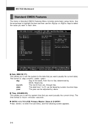
... 31 can be keyed by users. Date (MM:DD:YY) This allows you to set the system time that you want (usually the current time). MS-7522 Mainboard Standard CMOS Features The items in each item.
... 31 can be keyed by users. Date (MM:DD:YY) This allows you to set the system time that you want (usually the current time). MS-7522 Mainboard Standard CMOS Features The items in each item.
User Guide
Page 49
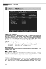
... APIC mode will allow users to use the arrow keys on the numeric keypad. Setting to [Off] will expand available IRQ resources for the system. 3-8 MS-7522 Mainboard Advanced BIOS Features BIOS Flash Protection W hen enabled, the BIOS' data cannot be changed when attempting to update the BIOS with PC2001 design guide...
... APIC mode will allow users to use the arrow keys on the numeric keypad. Setting to [Off] will expand available IRQ resources for the system. 3-8 MS-7522 Mainboard Advanced BIOS Features BIOS Flash Protection W hen enabled, the BIOS' data cannot be changed when attempting to update the BIOS with PC2001 design guide...


