User Guide
Page 7
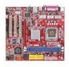
The PM8PM-V Series is based on VIA® P4M800Pro chipset & VIA® VT8237RPlus chipset for choosing the PM8PM-V Series (MS-7222 v2.0) Micro-ATX Mainboard. Layout 1 Introduction Thank you for optimal system efficiency. Designed to fit Intel® Pentium® 4/ Prescott (LGA 775) processor, the PM8PM -V Series delivers a high performance and professional desktop platform solution.
The PM8PM-V Series is based on VIA® P4M800Pro chipset & VIA® VT8237RPlus chipset for choosing the PM8PM-V Series (MS-7222 v2.0) Micro-ATX Mainboard. Layout 1 Introduction Thank you for optimal system efficiency. Designed to fit Intel® Pentium® 4/ Prescott (LGA 775) processor, the PM8PM -V Series delivers a high performance and professional desktop platform solution.
User Guide
Page 8
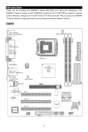
...240 Pin/ 1.8V) l Supports a maximum memory size of 2GB (For the updated supporting memory modules, please visit: http://www.msi.com.tw/program/products/mainboard/mbd/pro_mbd_trp_list.php) 2 Ultra DMA 33/66/100/133 master mode PCI EIDE controller - Specifications CPU l Supports Intel® ...to 3.8GHz, and Intel® P4 Prescott Celeron CPU (For the latest information about CPU, please visit: http://www.msi.com.tw/program/products/mainboard/mbd/pro_mbd_cpu_support.php) Chipset l VIA® P4M800Pro chipset - Integrated Hardware Sound Blaster/ Direct Sound AC97 audio - Supports ...
...240 Pin/ 1.8V) l Supports a maximum memory size of 2GB (For the updated supporting memory modules, please visit: http://www.msi.com.tw/program/products/mainboard/mbd/pro_mbd_trp_list.php) 2 Ultra DMA 33/66/100/133 master mode PCI EIDE controller - Specifications CPU l Supports Intel® ...to 3.8GHz, and Intel® P4 Prescott Celeron CPU (For the latest information about CPU, please visit: http://www.msi.com.tw/program/products/mainboard/mbd/pro_mbd_cpu_support.php) Chipset l VIA® P4M800Pro chipset - Integrated Hardware Sound Blaster/ Direct Sound AC97 audio - Supports ...
User Guide
Page 10
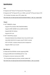
BIOS l The mainboard BIOS provides "Plug & Play" BIOS which detects the peripheral devices and expansion cards of the board automatically. l The mainboard provides a Desktop Management Interface (DMI) function that records your mainboard specifications. Audio l AC97 link controller integrated in VT8237R plus l Realtek ALC655 6-channel software audio codec l Compliance with AC97 v2.3 Spec. Dimension l Micro-ATX Form Factor Size: 244mm(L) x 210mm(W) Mounting l 6 standard mounting holes 4
BIOS l The mainboard BIOS provides "Plug & Play" BIOS which detects the peripheral devices and expansion cards of the board automatically. l The mainboard provides a Desktop Management Interface (DMI) function that records your mainboard specifications. Audio l AC97 link controller integrated in VT8237R plus l Realtek ALC655 6-channel software audio codec l Compliance with AC97 v2.3 Spec. Dimension l Micro-ATX Form Factor Size: 244mm(L) x 210mm(W) Mounting l 6 standard mounting holes 4
User Guide
Page 11
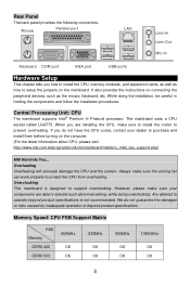
...to setup the jumpers on the computer. (For the latest information about CPU, please visit: http://www.msi.com.tw/program/products/mainboard/mbd/pro_mbd_cpu_support.php) MSI Reminds You... The mainboard uses a CPU socket called LGA775. Memory Speed/ CPU FSB Support Matrix FSB Memory DDRII 400 DDRII 533... components are installing the CPU, make sure the cooling fan can work properly to purchase and install them before turning on the mainboard. Rear Panel The back panel provides the following connectors: Hardware Setup This chapter tells you how to install the CPU, memory ...
...to setup the jumpers on the computer. (For the latest information about CPU, please visit: http://www.msi.com.tw/program/products/mainboard/mbd/pro_mbd_cpu_support.php) MSI Reminds You... The mainboard uses a CPU socket called LGA775. Memory Speed/ CPU FSB Support Matrix FSB Memory DDRII 400 DDRII 533... components are installing the CPU, make sure the cooling fan can work properly to purchase and install them before turning on the mainboard. Rear Panel The back panel provides the following connectors: Hardware Setup This chapter tells you how to install the CPU, memory ...
User Guide
Page 12
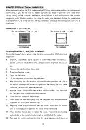
... not, take out the CPU with the hook under retention tab. 10. Align the holes on CPU before turning on the computer. Turn over the mainboard to protect the contact from lever hinge side. 3. Wrong installation will cause the damage of socket reveal. 4. Open the load lever. 5. Visually inspect if ...hooks. 12. Cover the load plate onto the package. 9. Then rotate the locking switch (refer to the correct direction marked on the edge of the mainboard. 11. Be sure to install the CPU & cooler correctly. Follow the steps below to grasp on it to fasten the cooler. Press the four ...
... not, take out the CPU with the hook under retention tab. 10. Align the holes on CPU before turning on the computer. Turn over the mainboard to protect the contact from lever hinge side. 3. Wrong installation will cause the damage of socket reveal. 4. Open the load lever. 5. Visually inspect if ...hooks. 12. Cover the load plate onto the package. 9. Then rotate the locking switch (refer to the correct direction marked on the edge of the mainboard. 11. Be sure to install the CPU & cooler correctly. Follow the steps below to grasp on it to fasten the cooler. Press the four ...
User Guide
Page 13
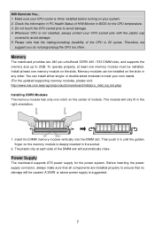
.../unmating durability of the DIMM slot will be installed. The module will only fit in BIOS for the power system. Power Supply The mainboard supports ATX power supply for the CPU temperature. 3. Please note that no damage will automatically close. Insert the DIMM memory module vertically into the ...properly, at each side of the CPU is not installed, always protect your system. 2. Do not touch the CPU socket pins to 2GB. MSI Reminds You... 1. Install at least one memory module must be caused. The plastic clip at least one memory module on the memory module is ...
.../unmating durability of the DIMM slot will be installed. The module will only fit in BIOS for the power system. Power Supply The mainboard supports ATX power supply for the CPU temperature. 3. Please note that no damage will automatically close. Insert the DIMM memory module vertically into the ...properly, at each side of the CPU is not installed, always protect your system. 2. Do not touch the CPU socket pins to 2GB. MSI Reminds You... 1. Install at least one memory module must be caused. The plastic clip at least one memory module on the memory module is ...
User Guide
Page 14
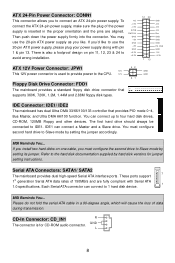
.... You must configure the second drive to four hard disk drives, CD-ROM, 120MB Floppy and other devices. MSI Reminds You... Refer to 1 hard disk device. MSI Reminds You... To connect the ATX 24-pin power supply, make sure the plug of data during transmission. You can connect a Master and a ...to the CPU. 12V 42 31 GND GND Floppy Disk Drive Connector: FDD1 The mainboard provides a standard floppy disk drive connector that provides PIO mode 0~4, Bus Master, and Ultra DMA 66/100 function. ATX 24-Pin Power Connector: CONN1 This connector allows you to Slave mode by setting ...
.... You must configure the second drive to four hard disk drives, CD-ROM, 120MB Floppy and other devices. MSI Reminds You... Refer to 1 hard disk device. MSI Reminds You... To connect the ATX 24-pin power supply, make sure the plug of data during transmission. You can connect a Master and a ...to the CPU. 12V 42 31 GND GND Floppy Disk Drive Connector: FDD1 The mainboard provides a standard floppy disk drive connector that provides PIO mode 0~4, Bus Master, and Ultra DMA 66/100 function. ATX 24-Pin Power Connector: CONN1 This connector allows you to Slave mode by setting ...
User Guide
Page 15
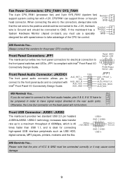
... wire is ideal for electrical connection to GND. CPUFAN1 can support three- If the mainboard has a System Hardware Monitor chipset on the back panel will not function. AUD_VCC AUD_GND AUD_FPOUT_R AUD_MIC_BIAS AUD_MIC 21 MSI Reminds You... Otherwise, the Line-Out connector on -board, you to Key AUD_FPOUT_L ...fan with AUD_RET_R Intel® Front Panel I /O 10 2 Connectivity Design Guide. Always consult the vendors for the proper CPU cooling fan. MSI Reminds You... Front USB Connector: JUSB1/ JUSB2 The mainboard provides two standard USB 2.0 pin headers JUSB1&JUSB2.
... wire is ideal for electrical connection to GND. CPUFAN1 can support three- If the mainboard has a System Hardware Monitor chipset on the back panel will not function. AUD_VCC AUD_GND AUD_FPOUT_R AUD_MIC_BIAS AUD_MIC 21 MSI Reminds You... Otherwise, the Line-Out connector on -board, you to Key AUD_FPOUT_L ...fan with AUD_RET_R Intel® Front Panel I /O 10 2 Connectivity Design Guide. Always consult the vendors for the proper CPU cooling fan. MSI Reminds You... Front USB Connector: JUSB1/ JUSB2 The mainboard provides two standard USB 2.0 pin headers JUSB1&JUSB2.
User Guide
Page 16
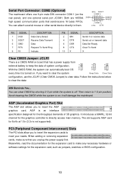
... system configuration. 1 2 1 2 1 2 With the CMOS RAM, the system can automatically boot OS 3 3 3 every time it will damage the mainboard. Then return to clear the data: MSI Reminds You... The slot supports AGP card for the graphics controller to clear data. Serial Port Connector: COM2 (Optional) The... mainboard offers one 9-pin male DIN connector COM 1 (on ; Avoid clearing the CMOS while the system is turned on ...
... system configuration. 1 2 1 2 1 2 With the CMOS RAM, the system can automatically boot OS 3 3 3 every time it will damage the mainboard. Then return to clear the data: MSI Reminds You... The slot supports AGP card for the graphics controller to clear data. Serial Port Connector: COM2 (Optional) The... mainboard offers one 9-pin male DIN connector COM 1 (on ; Avoid clearing the CMOS while the system is turned on ...
User Guide
Page 19
... password for BIOS. PnP/PCI Configurations This entry appears if your settings for power management. BIOS Setting Password Use this menu to set by the mainboard manufacturer specifically for optimal performance of your settings for integrated peripherals. Save & Exit Setup Save changes to CMOS and exit setup. Power Management Setup Use..., fan, and warning for overall system status. Exit Without Saving Abandon all changes and exit setup. 13 H/W Monitor This entry shows the status of the mainboard.
... password for BIOS. PnP/PCI Configurations This entry appears if your settings for power management. BIOS Setting Password Use this menu to set by the mainboard manufacturer specifically for optimal performance of your settings for integrated peripherals. Save & Exit Setup Save changes to CMOS and exit setup. Power Management Setup Use..., fan, and warning for overall system status. Exit Without Saving Abandon all changes and exit setup. 13 H/W Monitor This entry shows the status of the mainboard.

User Guide
Page 21
Load BIOS Defaults You can load the default values provided by the mainboard manufacturer for the stable performance. 15
Load BIOS Defaults You can load the default values provided by the mainboard manufacturer for the stable performance. 15
User Guide
Page 70
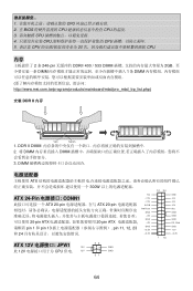
... 1 和 pin 13 pin 11, 12, 23 GND + 3 .3 V 和 24 + 3 .3 V 12 24 1 13 GND +5V +5V +5V Res GND GND GND PS -O N # GND -12V +3.3V ATX 12V JPW1 12V 此 12V CPU 供电. 12V 42 31 GND GND 64 1 CPU 2. 在 BIOS CPU CPU 的温度. 3 CPU 4 CPU CPU... 5. 请注意 CPU 20 CPU. 内存 2 条 240-pin DDRII 400 / 533 DIMM 2GB DIMM 1 条 DIMM http://www.msi.com.tw/program/products/mainboard/mbd/pro_mbd_trp_list.php) 安装 DDR II 内存 Volt Notch 1.
... 1 和 pin 13 pin 11, 12, 23 GND + 3 .3 V 和 24 + 3 .3 V 12 24 1 13 GND +5V +5V +5V Res GND GND GND PS -O N # GND -12V +3.3V ATX 12V JPW1 12V 此 12V CPU 供电. 12V 42 31 GND GND 64 1 CPU 2. 在 BIOS CPU CPU 的温度. 3 CPU 4 CPU CPU... 5. 请注意 CPU 20 CPU. 内存 2 条 240-pin DDRII 400 / 533 DIMM 2GB DIMM 1 条 DIMM http://www.msi.com.tw/program/products/mainboard/mbd/pro_mbd_trp_list.php) 安装 DDR II 内存 Volt Notch 1.
User Guide
Page 82
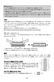
...PWR OK GND +5V GND +5V GND + 3 .3 V + 3 .3 V 12 24 1 13 GND +5V +5V +5V Res GND GND GND PS -O N # GND -12V +3.3V ATX 12V JPW1 12V 此 12V CPU 供電. 12V 42 31 GND GND 76 1 CPU 2. 在 BIOS CPU CPU 的溫度. 3 CPU 4 CPU CPU... 5. 請注意 CPU 20 CPU. 記憶體 2 條 240-pin DDRII 400 / 533 DIMM 2GB DIMM 1 條 DIMM http://www.msi.com.tw/program/products/mainboard/mbd/pro_mbd_trp_list.php) 安裝 DDR II 記憶體 DDR II DIMM Volt Notch 1. 將 DIMM DIMM 2.
...PWR OK GND +5V GND +5V GND + 3 .3 V + 3 .3 V 12 24 1 13 GND +5V +5V +5V Res GND GND GND PS -O N # GND -12V +3.3V ATX 12V JPW1 12V 此 12V CPU 供電. 12V 42 31 GND GND 76 1 CPU 2. 在 BIOS CPU CPU 的溫度. 3 CPU 4 CPU CPU... 5. 請注意 CPU 20 CPU. 記憶體 2 條 240-pin DDRII 400 / 533 DIMM 2GB DIMM 1 條 DIMM http://www.msi.com.tw/program/products/mainboard/mbd/pro_mbd_trp_list.php) 安裝 DDR II 記憶體 DDR II DIMM Volt Notch 1. 將 DIMM DIMM 2.
User Guide
Page 94
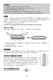
... DDRII 400 / 533 DIMM http://www.msi.com.tw/program/products/mainboard/mbd/pro_mbd_trp_list.php) DDRII Volt Notch 1. DIMM 電源 ATX 12 24 NC ATX 24 CONN1 ATX 電源 24 +12V +12V 5VSB PWR OK GND +5V 20 ピンの ATX GND +5V 11/12/23/24 GND + 3 .3 V ATX 12V JPW1 + 3 .3 V 42 1 13 こ...
... DDRII 400 / 533 DIMM http://www.msi.com.tw/program/products/mainboard/mbd/pro_mbd_trp_list.php) DDRII Volt Notch 1. DIMM 電源 ATX 12 24 NC ATX 24 CONN1 ATX 電源 24 +12V +12V 5VSB PWR OK GND +5V 20 ピンの ATX GND +5V 11/12/23/24 GND + 3 .3 V ATX 12V JPW1 + 3 .3 V 42 1 13 こ...


