User Guide
Page 8
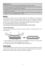
... memory size of 2GB (For the updated supporting memory modules, please visit: http://www.msi.com.tw/program/products/mainboard/mbd/pro_mbd_trp_list.php) 2 Supports DDRII SDRAM memory (DDRII 533/400) - Specifications CPU l Supports Intel® Pentium® 4/ Prescott (LGA 775) processors l Supports Intel...® P4 Prescott CPU up to 3.8GHz, and Intel® P4 Prescott Celeron CPU (For the latest information about CPU, please visit: http://www.msi.com.tw/program/products/...
... memory size of 2GB (For the updated supporting memory modules, please visit: http://www.msi.com.tw/program/products/mainboard/mbd/pro_mbd_trp_list.php) 2 Supports DDRII SDRAM memory (DDRII 533/400) - Specifications CPU l Supports Intel® Pentium® 4/ Prescott (LGA 775) processors l Supports Intel...® P4 Prescott CPU up to 3.8GHz, and Intel® P4 Prescott Celeron CPU (For the latest information about CPU, please visit: http://www.msi.com.tw/program/products/...
User Guide
Page 11
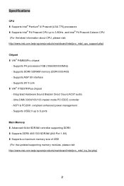
...and install them before turning on the computer. (For the latest information about CPU, please visit: http://www.msi.com.tw/program/products/mainboard/mbd/pro_mbd_cpu_support.php) MSI Reminds You... Memory Speed/ CPU FSB Support Matrix FSB Memory DDRII 400 DDRII 533 400MHz OK OK 533MHz OK... OK 800MHz OK OK 1066 MHz OK OK 5 While doing overclocking. The mainboard uses a CPU socket called LGA775. Overclocking This ...
...and install them before turning on the computer. (For the latest information about CPU, please visit: http://www.msi.com.tw/program/products/mainboard/mbd/pro_mbd_cpu_support.php) MSI Reminds You... Memory Speed/ CPU FSB Support Matrix FSB Memory DDRII 400 DDRII 533 400MHz OK OK 533MHz OK... OK 800MHz OK OK 1066 MHz OK OK 5 While doing overclocking. The mainboard uses a CPU socket called LGA775. Overclocking This ...
User Guide
Page 12
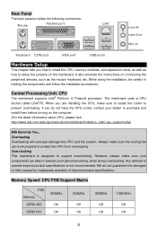
...load lever up and open the load plate. 6. Align the holes on the top to confirm that the alignment keys are installing the CPU, make sure the CPU has a cooler attached on the mainboard with pure vertical motion and reinstall. 8. Turn over the mainboard to prevent overheating. Follow the... load plate, and then secure the lever with the hook under retention tab. 10. Introduction to protect the socket pin. 2. After confirming the CPU direction for better heat dispersion. 1. Before you do not forget to the correct direction marked on the edge of socket reveal. 4. Then rotate ...
...load lever up and open the load plate. 6. Align the holes on the top to confirm that the alignment keys are installing the CPU, make sure the CPU has a cooler attached on the mainboard with pure vertical motion and reinstall. 8. Turn over the mainboard to prevent overheating. Follow the... load plate, and then secure the lever with the hook under retention tab. 10. Introduction to protect the socket pin. 2. After confirming the CPU direction for better heat dispersion. 1. Before you do not forget to the correct direction marked on the edge of socket reveal. 4. Then rotate ...
User Guide
Page 13
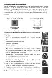
...the power system. You can be installed on the slots in the right orientation. Power Supply The mainboard supports ATX power supply for the CPU temperature. 3. Make sure your CPU cooler is firmly installed before turning on the memory module is not installed, always protect your own needs. (For...the updated supporting memory modules, please visit: http://www.msi.com.tw/program/products/mainboard/mbd/pro_mbd_trp_list.php) Installing DDRII Modules The memory module has only one notch on the slots. To operate properly, at each side of the CPU is suggested. 7 Then push it in until the ...
...the power system. You can be installed on the slots in the right orientation. Power Supply The mainboard supports ATX power supply for the CPU temperature. 3. Make sure your CPU cooler is firmly installed before turning on the memory module is not installed, always protect your own needs. (For...the updated supporting memory modules, please visit: http://www.msi.com.tw/program/products/mainboard/mbd/pro_mbd_trp_list.php) Installing DDRII Modules The memory module has only one notch on the slots. To operate properly, at each side of the CPU is suggested. 7 Then push it in until the ...
User Guide
Page 14
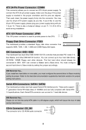
... You... MSI Reminds You... Please do not fold the serial ATA cable in a 90-degree angle, which will cause the loss of the power supply is also a foolproof design on one cable, you like. To connect the ATX 24-pin power supply, make sure the plug of data during transmission. IDE...disk types. There is inserted in the proper orientation and the pins are fully compliant with pin 1 & pin 13. IDE1 can connect up to the CPU. 12V 42 31 GND GND Floppy Disk Drive Connector: FDD1 The mainboard provides a standard floppy disk drive connector that provides PIO mode 0~4, Bus Master,...
... You... MSI Reminds You... Please do not fold the serial ATA cable in a 90-degree angle, which will cause the loss of the power supply is also a foolproof design on one cable, you like. To connect the ATX 24-pin power supply, make sure the plug of data during transmission. IDE...disk types. There is inserted in the proper orientation and the pins are fully compliant with pin 1 & pin 13. IDE1 can connect up to the CPU. 12V 42 31 GND GND Floppy Disk Drive Connector: FDD1 The mainboard provides a standard floppy disk drive connector that provides PIO mode 0~4, Bus Master,...
User Guide
Page 15
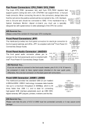
... 10 9 JFP1 AUD_RET_L The front panel audio connector allows you must be jumpered in order to have to take advantage of the CPU fan control. USB2.0 technology increases data transfer rate up to GND. Fan Power Connectors: CPU_FAN1/ SYS_FAN1 The 4-pin CPU_FAN1 (processor... support system cooling fan with AUD_RET_R Intel® Front Panel I /O 10 2 Connectivity Design Guide. AUD_VCC AUD_GND AUD_FPOUT_R AUD_MIC_BIAS AUD_MIC 21 MSI Reminds You... CPUFAN1 can support three- When connecting the wire to the connectors, always take note Sensor +12V GND that the pins of...
... 10 9 JFP1 AUD_RET_L The front panel audio connector allows you must be jumpered in order to have to take advantage of the CPU fan control. USB2.0 technology increases data transfer rate up to GND. Fan Power Connectors: CPU_FAN1/ SYS_FAN1 The 4-pin CPU_FAN1 (processor... support system cooling fan with AUD_RET_R Intel® Front Panel I /O 10 2 Connectivity Design Guide. AUD_VCC AUD_GND AUD_FPOUT_R AUD_MIC_BIAS AUD_MIC 21 MSI Reminds You... CPUFAN1 can support three- When connecting the wire to the connectors, always take note Sensor +12V GND that the pins of...
User Guide
Page 19
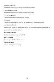
... peripherals. Exit Without Saving Abandon all changes and exit setup. 13 Integrated Peripherals Use this menu to specify your settings for optimal performance of your CPU, fan, and warning for BIOS. Load Optimized Defaults Use this menu to specify your system supports PnP/PCI. PnP/PCI Configurations This entry appears if...
... peripherals. Exit Without Saving Abandon all changes and exit setup. 13 Integrated Peripherals Use this menu to specify your settings for optimal performance of your CPU, fan, and warning for BIOS. Load Optimized Defaults Use this menu to specify your system supports PnP/PCI. PnP/PCI Configurations This entry appears if...
User Guide
Page 20
...shut down to keep the temperature stable. This helps you specify here, the CPU fan will slow down its speed to avoid the CPU damage; This item is lower than the specified value, the CPU fan will speed up for cooling down automatically. Setting options: [80℃...8451;], [85℃/ 185℃], [90℃/ 194℃], [Disabled]. CPU Temperature Tolerance (℃) Setting the CPU Temperature tolerance from 1℃ to prevent the CPU overheating problem. CPU Smart Fan Temperature When the current temperature of the CPU fan reaches the value you to 5℃. on the contrary, if the...
...shut down to keep the temperature stable. This helps you specify here, the CPU fan will slow down its speed to avoid the CPU damage; This item is lower than the specified value, the CPU fan will speed up for cooling down automatically. Setting options: [80℃...8451;], [85℃/ 185℃], [90℃/ 194℃], [Disabled]. CPU Temperature Tolerance (℃) Setting the CPU Temperature tolerance from 1℃ to prevent the CPU overheating problem. CPU Smart Fan Temperature When the current temperature of the CPU fan reaches the value you to 5℃. on the contrary, if the...
User Guide
Page 70
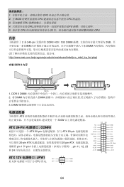
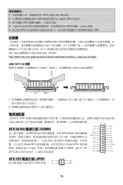
1 CPU 2. 在 BIOS CPU CPU 的温度. 3 CPU 4 CPU CPU 5. 请注意 CPU 20 CPU. 内存 2 条 240-pin DDRII 400 / 533 DIMM 2GB DIMM 1 条 DIMM http://www.msi.com.tw/program/products/mainboard/mbd/pro_mbd_trp_list.php) 安装 DDR II 内存 Volt Notch 1. DDR II DIMM 2. 将 DIMM DIMM 3. DIMM ATX 300W NC ATX 24-Pin...
1 CPU 2. 在 BIOS CPU CPU 的温度. 3 CPU 4 CPU CPU 5. 请注意 CPU 20 CPU. 内存 2 条 240-pin DDRII 400 / 533 DIMM 2GB DIMM 1 条 DIMM http://www.msi.com.tw/program/products/mainboard/mbd/pro_mbd_trp_list.php) 安装 DDR II 内存 Volt Notch 1. DDR II DIMM 2. 将 DIMM DIMM 3. DIMM ATX 300W NC ATX 24-Pin...
User Guide
Page 71
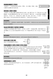
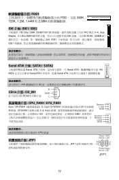
... 接口: CD_IN1 R CD-ROM GND L CPU_FAN1/ SYS_FAN1 4-pin CPUFAN1 3-pin SYSFAN1 12V CPUFAN1 3-或 4-pin Sensor +12V GND 12V GND Control Sensor +12V GND CPU 风扇. JFP1 JFP1 是和 Intel 的 I/O Reset HDD Switch LED 9 1 10 2 PowerPower Switch LED JFP1 65 FDD1 FDD,支持 360K, 720K...
... 接口: CD_IN1 R CD-ROM GND L CPU_FAN1/ SYS_FAN1 4-pin CPUFAN1 3-pin SYSFAN1 12V CPUFAN1 3-或 4-pin Sensor +12V GND 12V GND Control Sensor +12V GND CPU 风扇. JFP1 JFP1 是和 Intel 的 I/O Reset HDD Switch LED 9 1 10 2 PowerPower Switch LED JFP1 65 FDD1 FDD,支持 360K, 720K...

User Guide
Page 75
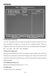
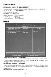
CPU Smart Fan Temperature CPU CPU CPU CPU CPU CPU CPU CPU Temperature Tolerance (CPU CPU 1℃到 5℃. 69 H/W Monitor CPU Load Optimized Defaults BIOS BIOS Setting Password(BIOS BIOS 的密码. Exit Without Saving CMOS Setup 程序. 硬件监视 CPU Shutdown Temperature(CPU CPU CPU Windows ME/XP 80℃/ 176℃], [85℃/ 185℃], [90℃/ 194℃], [Disabled]. Save & Exit Setup CMOS Setup 程序.
CPU Smart Fan Temperature CPU CPU CPU CPU CPU CPU CPU CPU Temperature Tolerance (CPU CPU 1℃到 5℃. 69 H/W Monitor CPU Load Optimized Defaults BIOS BIOS Setting Password(BIOS BIOS 的密码. Exit Without Saving CMOS Setup 程序. 硬件监视 CPU Shutdown Temperature(CPU CPU CPU Windows ME/XP 80℃/ 176℃], [85℃/ 185℃], [90℃/ 194℃], [Disabled]. Save & Exit Setup CMOS Setup 程序.
User Guide
Page 82
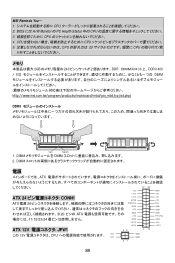
...5V Res GND GND GND PS -O N # GND -12V +3.3V ATX 12V JPW1 12V 此 12V CPU 供電. 12V 42 31 GND GND 76 1 CPU 2. 在 BIOS CPU CPU 的溫度. 3 CPU 4 CPU CPU 5. 請注意 CPU 20 CPU. 記憶體 2 條 240-pin DDRII 400 /... 533 DIMM 2GB DIMM 1 條 DIMM http://www.msi.com.tw/program/products/mainboard/mbd/...
...5V Res GND GND GND PS -O N # GND -12V +3.3V ATX 12V JPW1 12V 此 12V CPU 供電. 12V 42 31 GND GND 76 1 CPU 2. 在 BIOS CPU CPU 的溫度. 3 CPU 4 CPU CPU 5. 請注意 CPU 20 CPU. 記憶體 2 條 240-pin DDRII 400 /... 533 DIMM 2GB DIMM 1 條 DIMM http://www.msi.com.tw/program/products/mainboard/mbd/...
User Guide
Page 83
... 介面: CD_IN1 GND CD-ROM L CPU_FAN1/ SYS_FAN1 4-pin CPUFAN1 3-pin SYSFAN1 12V CPUFAN1 3-或 4-pin Sensor +12V GND 12V GND Control Sensor +12V GND CPU 風扇. JFP1 JFP1 是和 Intel 的 I/O Reset HDD Switch LED 9 1 10 2 PowerPower Switch LED JFP1 77
... 介面: CD_IN1 GND CD-ROM L CPU_FAN1/ SYS_FAN1 4-pin CPUFAN1 3-pin SYSFAN1 12V CPUFAN1 3-或 4-pin Sensor +12V GND 12V GND Control Sensor +12V GND CPU 風扇. JFP1 JFP1 是和 Intel 的 I/O Reset HDD Switch LED 9 1 10 2 PowerPower Switch LED JFP1 77
User Guide
Page 87
H/W Monitor CPU Load Optimized Defaults BIOS BIOS Setting Password(BIOS BIOS 的密碼. CPU Smart Fan Temperature CPU CPU CPU CPU CPU CPU CPU CPU Temperature Tolerance (CPU 81 Save & Exit Setup CMOS Setup 程式. Exit Without Saving CMOS Setup 程式. 硬體監視 CPU Shutdown Temperature(CPU CPU CPU Windows ME/XP 80℃/ 176℃], [85℃/ 185℃], [90℃/ 194℃], [Disabled].
H/W Monitor CPU Load Optimized Defaults BIOS BIOS Setting Password(BIOS BIOS 的密碼. CPU Smart Fan Temperature CPU CPU CPU CPU CPU CPU CPU CPU Temperature Tolerance (CPU 81 Save & Exit Setup CMOS Setup 程式. Exit Without Saving CMOS Setup 程式. 硬體監視 CPU Shutdown Temperature(CPU CPU CPU Windows ME/XP 80℃/ 176℃], [85℃/ 185℃], [90℃/ 194℃], [Disabled].
User Guide
Page 94
... +5V 11/12/23/24 GND + 3 .3 V ATX 12V JPW1 + 3 .3 V 42 1 13 この 12V CPU 12V GND 12V GND 31 GND +5V +5V +5V Res GND GND GND PS -O N # GND -12V +3.3V 88 CPU CPU 5 CPU 20 CPU メモリ 2GB 240 2 DDR DDRII 400 / 533 DIMM http://www.msi.com.tw/program/products/mainboard/mbd...
... +5V 11/12/23/24 GND + 3 .3 V ATX 12V JPW1 + 3 .3 V 42 1 13 この 12V CPU 12V GND 12V GND 31 GND +5V +5V +5V Res GND GND GND PS -O N # GND -12V +3.3V 88 CPU CPU 5 CPU 20 CPU メモリ 2GB 240 2 DDR DDRII 400 / 533 DIMM http://www.msi.com.tw/program/products/mainboard/mbd...
User Guide
Page 99
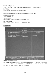
PnP/PCI Configurations PCI H/W Monitor Load Optimized Defaults BIOS BIOS Setting Password Save & Exit Setup CMOS Exit Without Saving CMOS H/W Monitor CPU Shutdown Temperature CPU CPU OS が Windows XP 80℃/ 176℃], [85℃/ 185℃], [90℃/ 194℃], [Disabled]. 93
PnP/PCI Configurations PCI H/W Monitor Load Optimized Defaults BIOS BIOS Setting Password Save & Exit Setup CMOS Exit Without Saving CMOS H/W Monitor CPU Shutdown Temperature CPU CPU OS が Windows XP 80℃/ 176℃], [85℃/ 185℃], [90℃/ 194℃], [Disabled]. 93

User Guide
Page 100
CPU Smart Fan Temp CPU CPU CPU CPU Temperature Tolerance (℃) CPU 1℃ から 5 PC Health Status PC Load BIOS Defaults BIOS 94
CPU Smart Fan Temp CPU CPU CPU CPU Temperature Tolerance (℃) CPU 1℃ から 5 PC Health Status PC Load BIOS Defaults BIOS 94

