
User Manual
Page 8
... WEEE (Waste Electrical and Electronic Equipment) Statement v English ...En-1 Specifications ...En-1 How to use this Installation Guide En-3 Central Processing Unit: CPU En-4 Memory ...En-5 Connectors, Jumpers, Slots En-6 Back Panel ...En-12 BIOS Setup ...En-14 Software Information En-16 G e rm an... ...De-1 Spezifikationen De-1 "W ie Sie diese Installationsanleitung verwenden De-3 Hauptprozessor: CPU De-4 Speicher ...De-5 Anschlüsse, Steckbrücken und Slots De-6 Hinteres Anschlusspaneel De-12 BIOS Setup ...De-14 Software ...
... WEEE (Waste Electrical and Electronic Equipment) Statement v English ...En-1 Specifications ...En-1 How to use this Installation Guide En-3 Central Processing Unit: CPU En-4 Memory ...En-5 Connectors, Jumpers, Slots En-6 Back Panel ...En-12 BIOS Setup ...En-14 Software Information En-16 G e rm an... ...De-1 Spezifikationen De-1 "W ie Sie diese Installationsanleitung verwenden De-3 Hauptprozessor: CPU De-4 Speicher ...De-5 Anschlüsse, Steckbrücken und Slots De-6 Hinteres Anschlusspaneel De-12 BIOS Setup ...De-14 Software ...

User Manual
Page 9
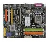
...VT6307 - wireless LAN and bluetooth combo card.) Form Factor - ATX (24.5 cm X 30.5 cm) Mounting - 9 mounting holes *For the latest information about CPU, please visit http:// www.ms i.com. com.t w/pro gram.../ product s/ mai nboard/ mbd/ pro_mbd_trp_lis t.php En-1 DDRII 533/667/800 SDRAM (8GB Max for DDRII 533/ 667, 4GB Max for MSI special ...Celeron D processors in the LGA775 package. North Bridge: Intel® P965 chipset - Supports 7.1 channels audio out - SATA1~6 support RAID 0/ RAID 1/ RAID 0+1 or RAID 5 mode by ICH8R ...
...VT6307 - wireless LAN and bluetooth combo card.) Form Factor - ATX (24.5 cm X 30.5 cm) Mounting - 9 mounting holes *For the latest information about CPU, please visit http:// www.ms i.com. com.t w/pro gram.../ product s/ mai nboard/ mbd/ pro_mbd_trp_lis t.php En-1 DDRII 533/667/800 SDRAM (8GB Max for DDRII 533/ 667, 4GB Max for MSI special ...Celeron D processors in the LGA775 package. North Bridge: Intel® P965 chipset - Supports 7.1 channels audio out - SATA1~6 support RAID 0/ RAID 1/ RAID 0+1 or RAID 5 mode by ICH8R ...

User Manual
Page 12
... the contact from lever hinge side. 3. CPU & Cooler Installation Procedures for easy CPU installation. If not, take out the CPU with the hook under retention tab. 10. For the latest information about CPU, please visit http://www.msi.com.tw/program/products/mainboard/mbd/ pro_mbd_cpu_support.php.... Align the holes on the edge of the CPU is seated well into the holes of socket reveal. 4. En-4 The mainboard uses a CPU socket called Socket-775 for...
... the contact from lever hinge side. 3. CPU & Cooler Installation Procedures for easy CPU installation. If not, take out the CPU with the hook under retention tab. 10. For the latest information about CPU, please visit http://www.msi.com.tw/program/products/mainboard/mbd/ pro_mbd_cpu_support.php.... Align the holes on the edge of the CPU is seated well into the holes of socket reveal. 4. En-4 The mainboard uses a CPU socket called Socket-775 for...

User Manual
Page 14
... connected to SATA connector Important Please do not fold the Serial ATA cable into 90-degree angle. Fan/heatsink with speed sensor to the recommended CPU fans at AMD® official website or consult the vendors for CPUFAN. 5 Floppy Disk Drive Connector (FDD connector) The mainboard provides a standard ...be connected to the +12V, the black wire is backwards compatible with +12V. Refer to 133 megabytes (MB) per second. Control SENSOR +1 2V GND CPU FAN SENSOR or NC +1 2V GND SYS FAN/ NB FAN/ POWER FAN Important Please refer to take note that supports 360K, 720K, 1.2M, 1.44M...
... connected to SATA connector Important Please do not fold the Serial ATA cable into 90-degree angle. Fan/heatsink with speed sensor to the recommended CPU fans at AMD® official website or consult the vendors for CPUFAN. 5 Floppy Disk Drive Connector (FDD connector) The mainboard provides a standard ...be connected to the +12V, the black wire is backwards compatible with +12V. Refer to 133 megabytes (MB) per second. Control SENSOR +1 2V GND CPU FAN SENSOR or NC +1 2V GND SYS FAN/ NB FAN/ POWER FAN Important Please refer to take note that supports 360K, 720K, 1.2M, 1.44M...
User Manual
Page 17
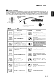
... overclocking users. It integrates four LEDs and allows users to the screen. 3 4 controller. 1 Processor Initialization 2 This will show information regarding 1 2 BootAttempt This will start detecting CPU clock, 4 checking type ofvideo onboard. properly. 1 2 Decompressing BIOS image to RAM 1 2 Assign Resources to all problems that support both USB1.1 & 2.0 spec. These users can debug...
... overclocking users. It integrates four LEDs and allows users to the screen. 3 4 controller. 1 Processor Initialization 2 This will show information regarding 1 2 BootAttempt This will start detecting CPU clock, 4 checking type ofvideo onboard. properly. 1 2 Decompressing BIOS image to RAM 1 2 Assign Resources to all problems that support both USB1.1 & 2.0 spec. These users can debug...

User Manual
Page 18
...connector. 3.3V 3.3V 1 11 23 ATX 12V Power Connector (2x2-Pin) These 12V power connectors is used to provide power to the CPU. 21 GND GND 12V 12V 43 24 ATX 12V Power Connector (2x4-Pin) These 12V... power connectors is used to provide power to the CPU. +12V +12V +12V +12V 51 GND GND GND GND 84 25 ATX 12V Power Connector (1x4-Pin) These 12V power connectors is turned on ...firmly into the connector. Avoid clearing the CMOS while the system is 1-2 pin off . To connect the ATX 20-pin power supply, make sure the plug of the Clear CMOS Jumper is on . it is ...
...connector. 3.3V 3.3V 1 11 23 ATX 12V Power Connector (2x2-Pin) These 12V power connectors is used to provide power to the CPU. 21 GND GND 12V 12V 43 24 ATX 12V Power Connector (2x4-Pin) These 12V... power connectors is used to provide power to the CPU. +12V +12V +12V +12V 51 GND GND GND GND 84 25 ATX 12V Power Connector (1x4-Pin) These 12V power connectors is turned on ...firmly into the connector. Avoid clearing the CMOS while the system is 1-2 pin off . To connect the ATX 20-pin power supply, make sure the plug of the Clear CMOS Jumper is on . it is ...

