User Guide
Page 2
... guidance. ◙ Visit the MSI website for PCB 1.X Date December 2010 Technical Support If a problem arises with your system and no guarantee is the intellectual property of MICRO-STAR INTERNATIONAL. Revision History Revision V1.1 Revision History Update cover page for FAQ, technical guide, BIOS updates, driver updates, and other information: http://www.msi.com/index.php?func=service ◙ Contact our technical...
... guidance. ◙ Visit the MSI website for PCB 1.X Date December 2010 Technical Support If a problem arises with your system and no guarantee is the intellectual property of MICRO-STAR INTERNATIONAL. Revision History Revision V1.1 Revision History Update cover page for FAQ, technical guide, BIOS updates, driver updates, and other information: http://www.msi.com/index.php?func=service ◙ Contact our technical...
User Guide
Page 8
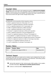
... Technical Support ii Safety Instructions iii FCC-B Radio Frequency Interference Statement iv WEEE (Waste Electrical and Electronic Equipment) Statement v Chapter 1 Getting Started 1-1 Mainboard Specifications 1-2 Mainboard Layout 1-4 Packing Checklist 1-5 Chapter 2 Hardware Setup 2-1 Quick Components Guide 2-2 Screw Holes 2-3 CPU (Central Processing Unit 2-4 Memory 2-8 Power Supply 2-10 Back Panel 2-11 Connectors 2-14 LED Status Indicators (optional 2-21 Jumper 2-22 Slots 2-23 Chapter 3 BIOS Setup 3-1 Entering Setup 3-2 The Main Menu 3-4 Green Power 3-5 Utility 3-6 OC...
... Technical Support ii Safety Instructions iii FCC-B Radio Frequency Interference Statement iv WEEE (Waste Electrical and Electronic Equipment) Statement v Chapter 1 Getting Started 1-1 Mainboard Specifications 1-2 Mainboard Layout 1-4 Packing Checklist 1-5 Chapter 2 Hardware Setup 2-1 Quick Components Guide 2-2 Screw Holes 2-3 CPU (Central Processing Unit 2-4 Memory 2-8 Power Supply 2-10 Back Panel 2-11 Connectors 2-14 LED Status Indicators (optional 2-21 Jumper 2-22 Slots 2-23 Chapter 3 BIOS Setup 3-1 Entering Setup 3-2 The Main Menu 3-4 Green Power 3-5 Utility 3-6 OC...
User Guide
Page 12
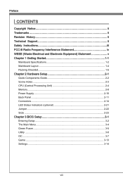
... up to 400Mbps Audio ■ Chip integrated by Realtek® ALC892 ■ Flexible 8-channel audio with jack sensing ■ Compliant with Azalia 1.0 Spec SATA ■ 2 SATA 6Gb/s (SATA1~2) ports by Intel® P67 ■ 4 SATA 3Gb/s (SATA3~6) ports by Intel® P67 RAID ■ SATA1~2 support Intel® Matrix Storage Technology (AHCI/ RAID 0/ 1) by Intel® P67 ■ SATA3~6 support Intel® Matrix Storage Technology (AHCI/ RAID 0/ 1/ 5/ 10) by Intel® P67 USB 3.0 (for P67A-C45...
... up to 400Mbps Audio ■ Chip integrated by Realtek® ALC892 ■ Flexible 8-channel audio with jack sensing ■ Compliant with Azalia 1.0 Spec SATA ■ 2 SATA 6Gb/s (SATA1~2) ports by Intel® P67 ■ 4 SATA 3Gb/s (SATA3~6) ports by Intel® P67 RAID ■ SATA1~2 support Intel® Matrix Storage Technology (AHCI/ RAID 0/ 1) by Intel® P67 ■ SATA3~6 support Intel® Matrix Storage Technology (AHCI/ RAID 0/ 1/ 5/ 10) by Intel® P67 USB 3.0 (for P67A-C45...
User Guide
Page 13
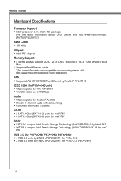
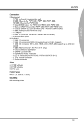
... only) - 1 LAN port - 2 USB 3.0 ports (for P67A-C45 / P67A-C43/ P67A-S40) - 6 flexible audio ports ■ On-Board - 1 USB 2.0 connector - 1 USB 3.0 connector (P67A-C45 supports up to USB 3.0 speed) 1 USB 3.0 connector (P67A-C43, P67S-C43 & P67A-S40 support up to USB 2.0 speed) - 1 IEEE 1394 connector (for P67A-C45 only) - 1 Chassis Intrusion connector - 1 S/PDIF-Out connector - 1 Front Panel Audio connector - 1 CD-In connector (for P67A-C45 / P67A-C43/ P67S-C43) - 1 TPM Module connector - 1 Serial connector Slots ■ 1 PCIE x16 slot ■ 3 PCIE x1 slots ■ 3 PCI slots Form Factor...
... only) - 1 LAN port - 2 USB 3.0 ports (for P67A-C45 / P67A-C43/ P67A-S40) - 6 flexible audio ports ■ On-Board - 1 USB 2.0 connector - 1 USB 3.0 connector (P67A-C45 supports up to USB 3.0 speed) 1 USB 3.0 connector (P67A-C43, P67S-C43 & P67A-S40 support up to USB 2.0 speed) - 1 IEEE 1394 connector (for P67A-C45 only) - 1 Chassis Intrusion connector - 1 S/PDIF-Out connector - 1 Front Panel Audio connector - 1 CD-In connector (for P67A-C45 / P67A-C43/ P67S-C43) - 1 TPM Module connector - 1 Serial connector Slots ■ 1 PCIE x16 slot ■ 3 PCIE x1 slots ■ 3 PCI slots Form Factor...

User Guide
Page 20
... operate beyond product specifications. Overclocking This mainboard is the Pin 1 indicator Alignment Key 2-4 Remember to apply some thermal paste on the computer. Make sure that you do not guarantee the damages or risks caused by inadequate operation or beyond product specifications is not recommended. Replacing the CPU While replacing the CPU, always turn off the ATX power supply or unplug the power supply's power cord from overheating...
... operate beyond product specifications. Overclocking This mainboard is the Pin 1 indicator Alignment Key 2-4 Remember to apply some thermal paste on the computer. Make sure that you do not guarantee the damages or risks caused by inadequate operation or beyond product specifications is not recommended. Replacing the CPU While replacing the CPU, always turn off the ATX power supply or unplug the power supply's power cord from overheating...

User Guide
Page 31
... can install Control Center utility that sends/receives 16 bytes FIFOs. the black wire is a 16550A high speed communication port that will automatically control the CPUFAN speeds according to the recommended CPU fans at processor's official website or consult the vendors for CPUFAN. Serial Port Connector: JCOM1 This connector is Ground and should be connected to GND. If the mainboard has a System Hardware Monitor chipset on-board, you must use a specially designed fan...
... can install Control Center utility that sends/receives 16 bytes FIFOs. the black wire is a 16550A high speed communication port that will automatically control the CPUFAN speeds according to the recommended CPU fans at processor's official website or consult the vendors for CPUFAN. Serial Port Connector: JCOM1 This connector is Ground and should be connected to GND. If the mainboard has a System Hardware Monitor chipset on-board, you must use a specially designed fan...

User Guide
Page 38
Avoid clearing the CMOS while the system is on . it is turned on ; Then return to keep the data of system configuration. If you want to clear the system configuration, set the jumper to clear data. 1 JBAT1 1 Keep Data 1 Clear Data Important You can automatically boot OS every time it will damage the mainboard. 2-22 With the CMOS RAM, the system can clear CMOS by shorting 2-3 pin while the system is off. Hardware Setup Jumper Clear CMOS Jumper: JBAT1 There is a CMOS RAM onboard that has a power supply from an external battery to 12 pin position.
Avoid clearing the CMOS while the system is on . it is turned on ; Then return to keep the data of system configuration. If you want to clear the system configuration, set the jumper to clear data. 1 JBAT1 1 Keep Data 1 Clear Data Important You can automatically boot OS every time it will damage the mainboard. 2-22 With the CMOS RAM, the system can clear CMOS by shorting 2-3 pin while the system is off. Hardware Setup Jumper Clear CMOS Jumper: JBAT1 There is a CMOS RAM onboard that has a power supply from an external battery to 12 pin position.

User Guide
Page 39
Meanwhile, read the documentation for the expansion card to configure any necessary hardware or software settings for the expansion card, such as jumpers, switches or BIOS configuration. 2-23 Chapter 2 Slots PCIE (Peripheral Component Interconnect Express) Slot The PCIE slot supports the PCIE interface expansion card. MS-7673 PCIE x16 Slot PCIE x1 Slot Important When adding or removing expansion cards, make sure that you unplug the power supply first.
Meanwhile, read the documentation for the expansion card to configure any necessary hardware or software settings for the expansion card, such as jumpers, switches or BIOS configuration. 2-23 Chapter 2 Slots PCIE (Peripheral Component Interconnect Express) Slot The PCIE slot supports the PCIE interface expansion card. MS-7673 PCIE x16 Slot PCIE x1 Slot Important When adding or removing expansion cards, make sure that you unplug the power supply first.

User Guide
Page 40
... lines over which devices can send interrupt signals to the PCI bus pins as jumpers, switches or BIOS configuration. PCI Interrupt Request Routing IRQ, or interrupt request line, are typically connected to the microprocessor. Hardware Setup PCI (Peripheral Component Interconnect) Slot The PCI slot supports LAN card, SCSI card, USB card, and other add-on cards that comply with PCI specifications. 32-bit PCI Slot Important When adding or removing expansion cards, make sure that you unplug the power supply first.
... lines over which devices can send interrupt signals to the PCI bus pins as jumpers, switches or BIOS configuration. PCI Interrupt Request Routing IRQ, or interrupt request line, are typically connected to the microprocessor. Hardware Setup PCI (Peripheral Component Interconnect) Slot The PCI slot supports LAN card, SCSI card, USB card, and other add-on cards that comply with PCI specifications. 32-bit PCI Slot Important When adding or removing expansion cards, make sure that you unplug the power supply first.

User Guide
Page 46
.../ 32 formats storage device. 3-6 When the data is lost or problems occur, you enter to the Live Update/ HDD Backup menu, please place the MSI Driver DVD that you don't need to search for the correct BIOS version throughout the website. ▶ HDD Backup This item is used to select the boot screen. It consists of the most common and important task. BIOS Setup Utility ▶ Memory Test This item...
.../ 32 formats storage device. 3-6 When the data is lost or problems occur, you enter to the Live Update/ HDD Backup menu, please place the MSI Driver DVD that you don't need to search for the correct BIOS version throughout the website. ▶ HDD Backup This item is used to select the boot screen. It consists of the most common and important task. BIOS Setup Utility ▶ Memory Test This item...

User Guide
Page 55
...-menu. ▶ ACPI Sleep State This item specifies the power saving modes for a longer time and thus improve the effective PCI bandwidth. Advance ▶ PCI Subsystem Settings Press to the SATA connectors on the mainboard. ▶ System Information It shows the information of your system (read only). The time format is . ▶ SATA Port1~6 It will show the device information that you connect the HDD devices...
...-menu. ▶ ACPI Sleep State This item specifies the power saving modes for a longer time and thus improve the effective PCI bandwidth. Advance ▶ PCI Subsystem Settings Press to the SATA connectors on the mainboard. ▶ System Information It shows the information of your system (read only). The time format is . ▶ SATA Port1~6 It will show the device information that you connect the HDD devices...

User Guide
Page 56
... to invoke the Boot ROM of the onboard LAN. == IEEE 1394 Configuration == ▶ Onboard IEEE 1394 Controller This item allows you to enable/ disable the onboard IEEE 1394 controller. == SATA Configuration == ▶ SATA Mode This item is used to specify RAID/ IDE/ AHCI mode for SATA port. == Audio Configuration == ▶ HD Audio Controller This item allows you to enable/ disable the HD audio controller. == HPET Configuration == ▶ HPET The HPET (High Precision Event Timers) is a component that is part of installed USB device. ▶ USB Controller This item...
... to invoke the Boot ROM of the onboard LAN. == IEEE 1394 Configuration == ▶ Onboard IEEE 1394 Controller This item allows you to enable/ disable the onboard IEEE 1394 controller. == SATA Configuration == ▶ SATA Mode This item is used to specify RAID/ IDE/ AHCI mode for SATA port. == Audio Configuration == ▶ HD Audio Controller This item allows you to enable/ disable the HD audio controller. == HPET Configuration == ▶ HPET The HPET (High Precision Event Timers) is a component that is part of installed USB device. ▶ USB Controller This item...

User Guide
Page 58
... [Enabled], the feature allows your system will be awakened from the power saving modes through any event on PCI or PCIE device. 3-18 Setting to [OS], the wake up events will reboot after a power failure or interrupt occurs. BIOS Setup ▶ CPU/ System Temperature, CPU FAN/ SYS FAN 1/ 2 Speed, CPU Vcore, CPU IO, CPU SA, DRAM Voltage, 3.3V, 5V, 12V These items show the current status of all of booting up the system on...
... [Enabled], the feature allows your system will be awakened from the power saving modes through any event on PCI or PCIE device. 3-18 Setting to [OS], the wake up events will reboot after a power failure or interrupt occurs. BIOS Setup ▶ CPU/ System Temperature, CPU FAN/ SYS FAN 1/ 2 Speed, CPU Vcore, CPU IO, CPU SA, DRAM Voltage, 3.3V, 5V, 12V These items show the current status of all of booting up the system on...
User Guide
Page 59
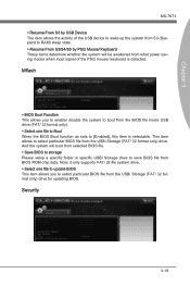
... to RAM) sleep state. ▶ Resume From S3/S4/S5 by USB Device The item allows the activity of the PS/2 mouse/ keyboard is selectable. And the system will boot from selected BIOS file. ▶ Save BIOS to storage Please setup a specific folder in specific USB/ Storage drive to save BIOS file from the BIOS file inside USB drive (FAT/ 32 format only). ▶ Select one file to update BIOS This item allows you to enable/ disable...
... to RAM) sleep state. ▶ Resume From S3/S4/S5 by USB Device The item allows the activity of the PS/2 mouse/ keyboard is selectable. And the system will boot from selected BIOS file. ▶ Save BIOS to storage Please setup a specific folder in specific USB/ Storage drive to save BIOS file from the BIOS file inside USB drive (FAT/ 32 format only). ▶ Select one file to update BIOS This item allows you to enable/ disable...

User Guide
Page 60
... [Enabled] later. 3-20 BIOS Setup ▶ Administrator Password This item is used to enable/ disable USB drive as a key. ▶ Make U-Key at When the "U-Key" as sets to [Enabled], this item is selectable. To clear a set password, just press when you to specify the USB drive. ▶ Chassis Intrusion Configuration Press to enter the sub-menu. ▶ Chassis Intrusion This item enables or disables the feature of your system configuration. ▶ U-Key This item is used to set the...
... [Enabled] later. 3-20 BIOS Setup ▶ Administrator Password This item is used to enable/ disable USB drive as a key. ▶ Make U-Key at When the "U-Key" as sets to [Enabled], this item is selectable. To clear a set password, just press when you to specify the USB drive. ▶ Chassis Intrusion Configuration Press to enter the sub-menu. ▶ Chassis Intrusion This item enables or disables the feature of your system configuration. ▶ U-Key This item is used to set the...

User Guide
Page 64
... HD Audio Configuration software utility is under continuous update to start installing the drivers. 5. cally appear. 2. Click Driver tab. 3. Select Realtek HD Audio Drivers to enhance audio applications. Click Finish to install the Realtek High Definition Audio Driver. 6. channel or 7.1+2 channel audio operations. Insert the application DVD into the DVD-ROM drive. A-2 Realtek Audio Installing the Realtek HD Audio Driver You need to install the HD audio driver for Realtek audio codec to function properly before you must install Windows® XP Service Pack3...
... HD Audio Configuration software utility is under continuous update to start installing the drivers. 5. cally appear. 2. Click Driver tab. 3. Select Realtek HD Audio Drivers to enhance audio applications. Click Finish to install the Realtek High Definition Audio Driver. 6. channel or 7.1+2 channel audio operations. Insert the application DVD into the DVD-ROM drive. A-2 Realtek Audio Installing the Realtek HD Audio Driver You need to install the HD audio driver for Realtek audio codec to function properly before you must install Windows® XP Service Pack3...

User Guide
Page 70
... mode is 2. When a Recovery volume is 3. B-2 Spreading the hard drive I/O load across independent channels greatly improves I/O performance. Intel® Rapid Recover Technology utilizes RAID 1 functionality to copy data from the illustrations in unison. All the information/ volumes/ pictures listed in excellent performance and good fault tolerance. The most popular implementations of Mirrors) , Intel® Matrix Storage Technology and Intel® Rapid Recover Technology. Supports...
... mode is 2. When a Recovery volume is 3. B-2 Spreading the hard drive I/O load across independent channels greatly improves I/O performance. Intel® Rapid Recover Technology utilizes RAID 1 functionality to copy data from the illustrations in unison. All the information/ volumes/ pictures listed in excellent performance and good fault tolerance. The most popular implementations of Mirrors) , Intel® Matrix Storage Technology and Intel® Rapid Recover Technology. Supports...
User Guide
Page 71
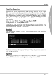
... RAID Configuration utility stored within the Intel RAID Option ROM. Also, you are reinstalling your system. It should be integrated with the system BIOS on all motherboards with a newly-built system or if you need to enable the RAID function in BIOS to enter the "Intel® RAID for a few seconds: Important The "Device Model", "Serial #" and "Size" in system boot-up, during the POST (Power-On Self Test). Please use + keys...
... RAID Configuration utility stored within the Intel RAID Option ROM. Also, you are reinstalling your system. It should be integrated with the system BIOS on all motherboards with a newly-built system or if you need to enable the RAID function in BIOS to enter the "Intel® RAID for a few seconds: Important The "Device Model", "Serial #" and "Size" in system boot-up, during the POST (Power-On Self Test). Please use + keys...

User Guide
Page 78
..., and Windows setup starts copying files. For Windows Vista/ Windows 7 you can use the USB floppy drive only. Important Please follow the instruction below to supply the driver. Select the appropriate Intel RAID controller and press ENTER. 8. You have selected the Intel® RAID controller. dows setup should be shown a list of one or more mass storage devices installed in step 3 and press Enter. 6. Press the "S" key to install a third party SCSI or RAID driver. 5. Note: For Windows XP...
..., and Windows setup starts copying files. For Windows Vista/ Windows 7 you can use the USB floppy drive only. Important Please follow the instruction below to supply the driver. Select the appropriate Intel RAID controller and press ENTER. 8. You have selected the Intel® RAID controller. dows setup should be shown a list of one or more mass storage devices installed in step 3 and press Enter. 6. Press the "S" key to install a third party SCSI or RAID driver. 5. Note: For Windows XP...

User Guide
Page 79
... System icon. 2. Choose the Hardware tab, then click the Device Manager tab. 3. B-11 Under the Driver tab, click on Intel RAID Drivers. 4. Click the "+" in front of the SCSI and RAID Controllers hardware type. The DVD will auto-run and the setup screen will be automatically installed. ■ Confirming Windows Driver Installation 1. Insert the MSI DVD into the DVD-ROM drive. 2. Appendix B MS-7673 ■ Existing Windows Driver Installation 1. The driver Intel(R) SATA RAID Controller should appear.
... System icon. 2. Choose the Hardware tab, then click the Device Manager tab. 3. B-11 Under the Driver tab, click on Intel RAID Drivers. 4. Click the "+" in front of the SCSI and RAID Controllers hardware type. The DVD will auto-run and the setup screen will be automatically installed. ■ Confirming Windows Driver Installation 1. Insert the MSI DVD into the DVD-ROM drive. 2. Appendix B MS-7673 ■ Existing Windows Driver Installation 1. The driver Intel(R) SATA RAID Controller should appear.


