User Guide
Page 2
... ■ Windows® is registered trademarks of Microsoft Corporation. ■ AMI® is registered trademark of American Megatrends Inc. ■ Award® is a registered trademark of Phoenix Technologies Ltd. ■ Sound Blaster® is registered trademark of Creative Technology Ltd. ...document is the intellectual property of MICRO-STAR INTERNATIONAL. Revision History Revision V1.1 Revision History Update cover page for FAQ, technical guide, BIOS updates, driver updates, and other information: http://www.msi.com/index.php?func=service ◙ Contact our technical staff at: ...
... ■ Windows® is registered trademarks of Microsoft Corporation. ■ AMI® is registered trademark of American Megatrends Inc. ■ Award® is a registered trademark of Phoenix Technologies Ltd. ■ Sound Blaster® is registered trademark of Creative Technology Ltd. ...document is the intellectual property of MICRO-STAR INTERNATIONAL. Revision History Revision V1.1 Revision History Update cover page for FAQ, technical guide, BIOS updates, driver updates, and other information: http://www.msi.com/index.php?func=service ◙ Contact our technical staff at: ...
User Guide
Page 8
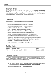
... Technical Support ii Safety Instructions iii FCC-B Radio Frequency Interference Statement iv WEEE (Waste Electrical and Electronic Equipment) Statement v Chapter 1 Getting Started 1-1 Mainboard Specifications 1-2 Mainboard Layout 1-4 Packing Checklist 1-5 Chapter 2 Hardware Setup 2-1 Quick Components Guide 2-2 Screw Holes 2-3 CPU (Central Processing Unit 2-4 Memory 2-8 Power Supply 2-10 Back Panel 2-11 Connectors 2-14 LED Status Indicators (optional 2-21 Jumper 2-22 Slots 2-23 Chapter 3 BIOS Setup 3-1 Entering Setup 3-2 The Main Menu 3-4 Green Power 3-5 Utility 3-6 OC...
... Technical Support ii Safety Instructions iii FCC-B Radio Frequency Interference Statement iv WEEE (Waste Electrical and Electronic Equipment) Statement v Chapter 1 Getting Started 1-1 Mainboard Specifications 1-2 Mainboard Layout 1-4 Packing Checklist 1-5 Chapter 2 Hardware Setup 2-1 Quick Components Guide 2-2 Screw Holes 2-3 CPU (Central Processing Unit 2-4 Memory 2-8 Power Supply 2-10 Back Panel 2-11 Connectors 2-14 LED Status Indicators (optional 2-21 Jumper 2-22 Slots 2-23 Chapter 3 BIOS Setup 3-1 Entering Setup 3-2 The Main Menu 3-4 Green Power 3-5 Utility 3-6 OC...
User Guide
Page 12
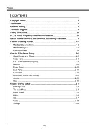
... Started Mainboard Specifications Processor Support ■ Intel® processor in the LGA1155 package (For the latest information about CPU, please visit http://www.msi.com/index. php?func=cpuform2) Base Clock ■ 100 MHz Chipset ■ Intel® P67 chipset Memory Support ■ 4 DDR3 DIMMs support DDR3 2133*(OC)/ 1600*(OC)/ 1333/ 1066 DRAM (16GB Max) ■ Supports Dual-Channel mode *(For more information on compatible components, please visit http://www.msi...
... Started Mainboard Specifications Processor Support ■ Intel® processor in the LGA1155 package (For the latest information about CPU, please visit http://www.msi.com/index. php?func=cpuform2) Base Clock ■ 100 MHz Chipset ■ Intel® P67 chipset Memory Support ■ 4 DDR3 DIMMs support DDR3 2133*(OC)/ 1600*(OC)/ 1333/ 1066 DRAM (16GB Max) ■ Supports Dual-Channel mode *(For more information on compatible components, please visit http://www.msi...
User Guide
Page 13
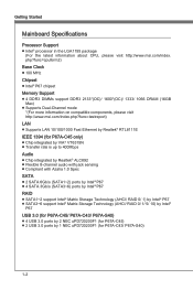
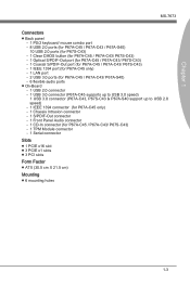
... Connectors ■ Back panel - 1 PS/2 keyboard/ mouse combo port - 8 USB 2.0 ports (for P67A-C45 / P67A-C43 / P67A-S40) 10 USB 2.0 ports (for P67S-C43) - 1 Clear CMOS button (for P67A-C45 / P67A-C43/ P67S-C43) - 1 Optical S/PDIF-Out port (for P67A-C45 / P67A-C43/ P67S-C43) - 1 Coaxial S/PDIF-Out port (for P67A-C45 / P67A-C43/ P67S-C43) - 1 IEEE 1394 port (for P67A-C45 only) - 1 LAN port - 2 USB 3.0 ports (for P67A-C45 / P67A-C43/ P67A-S40) - 6 flexible audio ports ■ On-Board - 1 USB 2.0 connector - 1 USB 3.0 connector (P67A-C45 supports up to USB 3.0 speed) 1 USB 3.0 connector (P67A...
... Connectors ■ Back panel - 1 PS/2 keyboard/ mouse combo port - 8 USB 2.0 ports (for P67A-C45 / P67A-C43 / P67A-S40) 10 USB 2.0 ports (for P67S-C43) - 1 Clear CMOS button (for P67A-C45 / P67A-C43/ P67S-C43) - 1 Optical S/PDIF-Out port (for P67A-C45 / P67A-C43/ P67S-C43) - 1 Coaxial S/PDIF-Out port (for P67A-C45 / P67A-C43/ P67S-C43) - 1 IEEE 1394 port (for P67A-C45 only) - 1 LAN port - 2 USB 3.0 ports (for P67A-C45 / P67A-C43/ P67A-S40) - 6 flexible audio ports ■ On-Board - 1 USB 2.0 connector - 1 USB 3.0 connector (P67A-C45 supports up to USB 3.0 speed) 1 USB 3.0 connector (P67A...
User Guide
Page 20
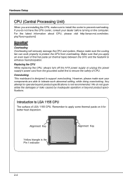
... damage the CPU and system. Replacing the CPU While replacing the CPU, always turn off the ATX power supply or unplug the power supply's power cord from overheating. Overclocking This mainboard is not recommended. Any attempt to operate beyond product specifications. For the latest information about CPU, please visit http://www.msi.com/index. We do not have the CPU cooler, consult your components are installing the CPU, make sure...
... damage the CPU and system. Replacing the CPU While replacing the CPU, always turn off the ATX power supply or unplug the power supply's power cord from overheating. Overclocking This mainboard is not recommended. Any attempt to operate beyond product specifications. For the latest information about CPU, please visit http://www.msi.com/index. We do not have the CPU cooler, consult your components are installing the CPU, make sure...
User Guide
Page 31
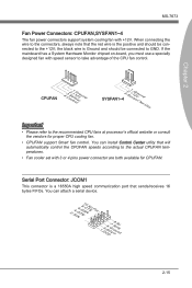
If the mainboard has a System Hardware Monitor chipset on-board, you must use a specially designed fan with +12V. Serial Port Connector: JCOM1 This connector is a 16550A high speed communication port that will automatically control the CPUFAN speeds according to the actual CPUFAN temperatures. • Fan cooler set with 3 or 4 pins power connector are both available for proper CPU cooling fan. • CPUFAN support Smart fan control. You can install Control Center utility that sends/receives 16 bytes FIFOs. the black wire is...
If the mainboard has a System Hardware Monitor chipset on-board, you must use a specially designed fan with +12V. Serial Port Connector: JCOM1 This connector is a 16550A high speed communication port that will automatically control the CPUFAN speeds according to the actual CPUFAN temperatures. • Fan cooler set with 3 or 4 pins power connector are both available for proper CPU cooling fan. • CPUFAN support Smart fan control. You can install Control Center utility that sends/receives 16 bytes FIFOs. the black wire is...
User Guide
Page 38
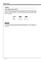
Hardware Setup Jumper Clear CMOS Jumper: JBAT1 There is a CMOS RAM onboard that has a power supply from an external battery to 12 pin position. Avoid clearing the CMOS while the system is off. Then return to keep the data of system configuration. it is turned on ; If you want to clear the system configuration, set the jumper to clear data. 1 JBAT1 1 Keep Data 1 Clear Data Important You can automatically boot OS every time it will damage the mainboard. 2-22 With the CMOS RAM, the system can clear CMOS by shorting 2-3 pin while the system is on .
Hardware Setup Jumper Clear CMOS Jumper: JBAT1 There is a CMOS RAM onboard that has a power supply from an external battery to 12 pin position. Avoid clearing the CMOS while the system is off. Then return to keep the data of system configuration. it is turned on ; If you want to clear the system configuration, set the jumper to clear data. 1 JBAT1 1 Keep Data 1 Clear Data Important You can automatically boot OS every time it will damage the mainboard. 2-22 With the CMOS RAM, the system can clear CMOS by shorting 2-3 pin while the system is on .
User Guide
Page 39
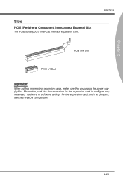
MS-7673 PCIE x16 Slot PCIE x1 Slot Important When adding or removing expansion cards, make sure that you unplug the power supply first. Meanwhile, read the documentation for the expansion card to configure any necessary hardware or software settings for the expansion card, such as jumpers, switches or BIOS configuration. 2-23 Chapter 2 Slots PCIE (Peripheral Component Interconnect Express) Slot The PCIE slot supports the PCIE interface expansion card.
MS-7673 PCIE x16 Slot PCIE x1 Slot Important When adding or removing expansion cards, make sure that you unplug the power supply first. Meanwhile, read the documentation for the expansion card to configure any necessary hardware or software settings for the expansion card, such as jumpers, switches or BIOS configuration. 2-23 Chapter 2 Slots PCIE (Peripheral Component Interconnect Express) Slot The PCIE slot supports the PCIE interface expansion card.
User Guide
Page 40
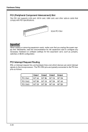
Hardware Setup PCI (Peripheral Component Interconnect) Slot The PCI slot supports LAN card, SCSI card, USB card, and other add-on cards that comply with PCI specifications. 32-bit PCI Slot Important When adding or removing expansion cards, make sure that you unplug the power supply first. Meanwhile, read the documentation for the expansion card to configure any necessary hardware or software settings for the expansion card, such as follows: PCI Slot1 PCI Slot2 PCI Slot3 Order1 INT A# INT B# INT...
Hardware Setup PCI (Peripheral Component Interconnect) Slot The PCI slot supports LAN card, SCSI card, USB card, and other add-on cards that comply with PCI specifications. 32-bit PCI Slot Important When adding or removing expansion cards, make sure that you unplug the power supply first. Meanwhile, read the documentation for the expansion card to configure any necessary hardware or software settings for the expansion card, such as follows: PCI Slot1 PCI Slot2 PCI Slot3 Order1 INT A# INT B# INT...

User Guide
Page 46
... mainboard package into the DVD-ROM drive . When the data is lost or problems occur, you enter to the Live Update/ HDD Backup menu, please place the MSI Driver DVD that be included in FAT12/ 16/ 32 formats storage device. 3-6 It consists of the most common and important task. Hard disk store backup and restore is one of backing up all the partition on image files. BIOS Setup Utility ▶ Memory...
... mainboard package into the DVD-ROM drive . When the data is lost or problems occur, you enter to the Live Update/ HDD Backup menu, please place the MSI Driver DVD that be included in FAT12/ 16/ 32 formats storage device. 3-6 It consists of the most common and important task. Hard disk store backup and restore is one of backing up all the partition on image files. BIOS Setup Utility ▶ Memory...
User Guide
Page 55
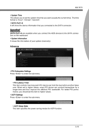
... you connect the HDD devices to enter the sub-menu. ▶ PCI Latency Timer This item controls how long each PCI device can conduct transactions for ACPI function. 3-15 Advance ▶ PCI Subsystem Settings Press to the SATA connectors on the mainboard. ▶ System Information It shows the information of your system (read only). For better PCI performance, you should set the item to higher values. ▶ ACPI Settings Press...
... you connect the HDD devices to enter the sub-menu. ▶ PCI Latency Timer This item controls how long each PCI device can conduct transactions for ACPI function. 3-15 Advance ▶ PCI Subsystem Settings Press to the SATA connectors on the mainboard. ▶ System Information It shows the information of your system (read only). For better PCI performance, you should set the item to higher values. ▶ ACPI Settings Press...

User Guide
Page 56
... to invoke the Boot ROM of the onboard LAN. == IEEE 1394 Configuration == ▶ Onboard IEEE 1394 Controller This item allows you to enable/ disable the onboard IEEE 1394 controller. == SATA Configuration == ▶ SATA Mode This item is used to specify RAID/ IDE/ AHCI mode for SATA port. == Audio Configuration == ▶ HD Audio Controller This item allows you to enable/ disable the HD audio controller. == HPET Configuration == ▶ HPET The HPET (High Precision Event Timers) is a component that is part of installed USB device. ▶ USB Controller This item...
... to invoke the Boot ROM of the onboard LAN. == IEEE 1394 Configuration == ▶ Onboard IEEE 1394 Controller This item allows you to enable/ disable the onboard IEEE 1394 controller. == SATA Configuration == ▶ SATA Mode This item is used to specify RAID/ IDE/ AHCI mode for SATA port. == Audio Configuration == ▶ HD Audio Controller This item allows you to enable/ disable the HD audio controller. == HPET Configuration == ▶ HPET The HPET (High Precision Event Timers) is a component that is part of installed USB device. ▶ USB Controller This item...

User Guide
Page 58
... is used to enable or disable the feature of the monitored hardware devices/components such as CPU voltage, temperatures and all of booting up the system on a scheduled time/date. ▶ Date/ HH:MM:SS If Resume By RTC Alarm is designed for Energy Using Products Lot 6 2013 (EuP) aka Energy Related Products (ErP). BIOS Setup ▶ CPU/ System Temperature, CPU FAN/ SYS FAN 1/ 2 Speed, CPU Vcore, CPU IO, CPU SA, DRAM Voltage...
... is used to enable or disable the feature of the monitored hardware devices/components such as CPU voltage, temperatures and all of booting up the system on a scheduled time/date. ▶ Date/ HH:MM:SS If Resume By RTC Alarm is designed for Energy Using Products Lot 6 2013 (EuP) aka Energy Related Products (ErP). BIOS Setup ▶ CPU/ System Temperature, CPU FAN/ SYS FAN 1/ 2 Speed, CPU Vcore, CPU IO, CPU SA, DRAM Voltage...
User Guide
Page 59
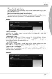
... from what power saving modes when input signal of the USB device to wake up the system from S3 (Suspend to RAM) sleep state. ▶ Resume From S3/S4/S5 by PS/2 Mouse/ Keyboard These items determine whether the system will boot from selected BIOS file. ▶ Save BIOS to storage Please setup a specific folder in specific USB/ Storage drive to save BIOS file from BIOS ROM chip data. Security 3-19 Mflash ▶ BIOS Boot Function...
... from what power saving modes when input signal of the USB device to wake up the system from S3 (Suspend to RAM) sleep state. ▶ Resume From S3/S4/S5 by PS/2 Mouse/ Keyboard These items determine whether the system will boot from selected BIOS file. ▶ Save BIOS to storage Please setup a specific folder in specific USB/ Storage drive to save BIOS file from BIOS ROM chip data. Security 3-19 Mflash ▶ BIOS Boot Function...

User Guide
Page 60
To clear a set password, just press when you can enter Setup/ OS without entering any part of your system configuration. ▶ U-Key This item is used to enable/ disable USB drive as a key. ▶ Make U-Key at When the "U-Key" as sets to enter the sub-menu. ▶ Chassis Intrusion This item enables or disables the feature of the field will be disabled. Once the password is disabled, the system will replace any previously set the administrator password. The password typed now...
To clear a set password, just press when you can enter Setup/ OS without entering any part of your system configuration. ▶ U-Key This item is used to enable/ disable USB drive as a key. ▶ Make U-Key at When the "U-Key" as sets to enter the sub-menu. ▶ Chassis Intrusion This item enables or disables the feature of the field will be disabled. Once the password is disabled, the system will replace any previously set the administrator password. The password typed now...

User Guide
Page 64
.... A-2 Insert the application DVD into the DVD-ROM drive. Click AUDIO button. Select Realtek HD Audio Drivers to install the Realtek High Definition Audio Driver. 6. Click Next to start installing the drivers. 5. Important The HD Audio Configuration software utility is under continuous update to restart the system. channel or 7.1+2 channel audio operations. The setup screen will automati- Click here 4. cally appear. 2. The following illustrations are based on -screen instructions to install drivers. 7. Hence, the program screens shown here in different...
.... A-2 Insert the application DVD into the DVD-ROM drive. Click AUDIO button. Select Realtek HD Audio Drivers to install the Realtek High Definition Audio Driver. 6. Click Next to start installing the drivers. 5. Important The HD Audio Configuration software utility is under continuous update to restart the system. channel or 7.1+2 channel audio operations. The setup screen will automati- Click here 4. cally appear. 2. The following illustrations are based on -screen instructions to install drivers. 7. Hence, the program screens shown here in different...

User Guide
Page 70
... RAID 10 mode is 2. Serial ATA uses long, thin cables, making it easier to separate hard drives. Supports 3 Gb/s transfers with the Intel RAID controller that allows you to a designated Recovery drive. RAID 0 breaks the data into blocks which are written to connect your drive and improving the airflow inside your system might differ from a designated Master drive to configure SATA hard drives as the Master volume. They are 2 methods of updating...
... RAID 10 mode is 2. Serial ATA uses long, thin cables, making it easier to separate hard drives. Supports 3 Gb/s transfers with the Intel RAID controller that allows you to a designated Recovery drive. RAID 0 breaks the data into blocks which are written to connect your drive and improving the airflow inside your system might differ from a designated Master drive to configure SATA hard drives as the Master volume. They are 2 methods of updating...
User Guide
Page 71
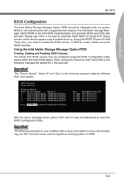
... POST (Power-On Self Test). After the above message shows, press and keys simultaneously to enter the "Intel® RAID for a few seconds: Important The "Device Model", "Serial #" and "Size" in the following procedure is the Intel RAID implementation and provides BIOS and DOS disk services. It should not be configured using the RAID Configuration utility stored within the Intel RAID Option ROM. B-3 The Intel Matrix Storage Manager Option ROM is only available with a supported...
... POST (Power-On Self Test). After the above message shows, press and keys simultaneously to enter the "Intel® RAID for a few seconds: Important The "Device Model", "Serial #" and "Size" in the following procedure is the Intel RAID implementation and provides BIOS and DOS disk services. It should not be configured using the RAID Configuration utility stored within the Intel RAID Option ROM. B-3 The Intel Matrix Storage Manager Option ROM is only available with a supported...
User Guide
Page 78
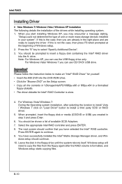
... Windows setup starts copying files. You should be shown a list of Windows setup. 2. Press ENTER again to select "Specify Additional Device". 3. When prompted, insert the floppy disk or media (CD/DVD or USB) you may encounter a message stating, "Setup could not determine the type of the drivers while installing operating system. 1. Windows setup will need to copy the files from the floppy again after selecting the location to install Vista / Windows 7 click on "Load Driver" button to...
... Windows setup starts copying files. You should be shown a list of Windows setup. 2. Press ENTER again to select "Specify Additional Device". 3. When prompted, insert the floppy disk or media (CD/DVD or USB) you may encounter a message stating, "Setup could not determine the type of the drivers while installing operating system. 1. Windows setup will need to copy the files from the floppy again after selecting the location to install Vista / Windows 7 click on "Load Driver" button to...
User Guide
Page 79
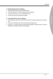
... Windows Driver Installation 1. Click the "+" in front of the SCSI and RAID Controllers hardware type. From Windows, open the Control Panel from My Computer followed by the System icon. 2. B-11 Under the Driver tab, click on Intel RAID Drivers. 4. Choose the Hardware tab, then click the Device Manager tab. 3. The DVD will auto-run and the setup screen will be automatically installed. ■ Confirming Windows Driver Installation 1. Insert the MSI DVD into the DVD-ROM drive...
... Windows Driver Installation 1. Click the "+" in front of the SCSI and RAID Controllers hardware type. From Windows, open the Control Panel from My Computer followed by the System icon. 2. B-11 Under the Driver tab, click on Intel RAID Drivers. 4. Choose the Hardware tab, then click the Device Manager tab. 3. The DVD will auto-run and the setup screen will be automatically installed. ■ Confirming Windows Driver Installation 1. Insert the MSI DVD into the DVD-ROM drive...


