
User Guide
Page 8
... (Waste Electrical and Electronic Equipment) Statement v Chapter 1 Getting Started 1-1 Mainboard Specifications 1-2 Mainboard Layout 1-4 Packing Checklist 1-5 Chapter 2 Hardware Setup 2-1 Quick Components Guide 2-2 CPU (Central Processing Unit 2-3 Memory 2-7 Power Supply 2-9 Back Panel 2-10 Connectors 2-11 Jumpers 2-17 Button 2-18 Slots 2-19 LED Status Indicators 2-25 Chapter 3 BIOS Setup 3-1 Entering Setup 3-2 The Main Menu...
... (Waste Electrical and Electronic Equipment) Statement v Chapter 1 Getting Started 1-1 Mainboard Specifications 1-2 Mainboard Layout 1-4 Packing Checklist 1-5 Chapter 2 Hardware Setup 2-1 Quick Components Guide 2-2 CPU (Central Processing Unit 2-3 Memory 2-7 Power Supply 2-9 Back Panel 2-10 Connectors 2-11 Jumpers 2-17 Button 2-18 Slots 2-19 LED Status Indicators 2-25 Chapter 3 BIOS Setup 3-1 Entering Setup 3-2 The Main Menu...
User Guide
Page 12
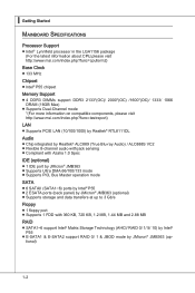
...Intel® Lynnfield processor in the LGA1156 package (For the latest information about CPU,please visit http://www.msi.com/index.php?func=cpuform2) Base Clock ■ 133 MHz Chipset ■ Intel® P55 chipset Memory Support ■ 4 DDR3 DIMMs support DDR3 2133*(OC)/ 2000*(OC) /1600*(OC)/ 1333/ 1066 DRAM (16GB... ■ Compliant with Azalia 1.0 Spec IDE (optional) ■ 1 IDE port by JMicron® JMB363 ■ Supports Ultra DMA 66/100/133 mode ■ Supports PIO, Bus Master operation mode SATA ■ 6 SATAII (SATA1~6) ports by Intel® P55 ■ 2 ESATA ports (back panel...
...Intel® Lynnfield processor in the LGA1156 package (For the latest information about CPU,please visit http://www.msi.com/index.php?func=cpuform2) Base Clock ■ 133 MHz Chipset ■ Intel® P55 chipset Memory Support ■ 4 DDR3 DIMMs support DDR3 2133*(OC)/ 2000*(OC) /1600*(OC)/ 1333/ 1066 DRAM (16GB... ■ Compliant with Azalia 1.0 Spec IDE (optional) ■ 1 IDE port by JMicron® JMB363 ■ Supports Ultra DMA 66/100/133 mode ■ Supports PIO, Bus Master operation mode SATA ■ 6 SATAII (SATA1~6) ports by Intel® P55 ■ 2 ESATA ports (back panel...

User Guide
Page 23
... DIMM1 DIMM4 DIMM3 2 DIMM2 DIMM1 DIMM4 DIMM3 Installed Empty Important • DDR3 memory modules are used for memory population rules. For more information on compatible components, please visit http://www.msi.com/index.php?func=testreport DDR3 240-pin, 1.5V 48x2=96 pin 72x2=...to 15+GB (not full 16GB) when each DIMM is not backwards compatible. The following illustrations for installing memory modules. Dual-Channel mode Population Rule In Dual-Channel mode, the memory modules can enhance the system performance. MS-7589 Memory These DIMM slots are not ...
... DIMM1 DIMM4 DIMM3 2 DIMM2 DIMM1 DIMM4 DIMM3 Installed Empty Important • DDR3 memory modules are used for memory population rules. For more information on compatible components, please visit http://www.msi.com/index.php?func=testreport DDR3 240-pin, 1.5V 48x2=96 pin 72x2=...to 15+GB (not full 16GB) when each DIMM is not backwards compatible. The following illustrations for installing memory modules. Dual-Channel mode Population Rule In Dual-Channel mode, the memory modules can enhance the system performance. MS-7589 Memory These DIMM slots are not ...

User Guide
Page 24
... is deeply inserted in until the golden finger on the center and will automatically close when the memory module is properly seated. 3. Manually check if the memory module has been locked in place by the DIMM slot clips at each side of the DIMM slot will only fit in the ...DIMM slot. 2-8 Insert the memory module vertically into the DIMM slot. The plastic clip at the sides. ▍ Hardware Setup Installing Memory Modules 1. The memory module has only one notch on the memory module is properly inserted in the right orientation. 2.
... is deeply inserted in until the golden finger on the center and will automatically close when the memory module is properly seated. 3. Manually check if the memory module has been locked in place by the DIMM slot clips at each side of the DIMM slot will only fit in the ...DIMM slot. 2-8 Insert the memory module vertically into the DIMM slot. The plastic clip at the sides. ▍ Hardware Setup Installing Memory Modules 1. The memory module has only one notch on the memory module is properly inserted in the right orientation. 2.

User Guide
Page 34
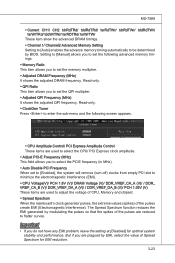
... provides the following buttons for you to save the OC Genie configuration to set the computer's function. Important Please install the DDR3 1333 and up memory and equip better heat sink/ cooler with OC Genie function. This section will increase/ decrease the Base clock frequency 1 MHz when the system is used...
... provides the following buttons for you to save the OC Genie configuration to set the computer's function. Important Please install the DDR3 1333 and up memory and equip better heat sink/ cooler with OC Genie function. This section will increase/ decrease the Base clock frequency 1 MHz when the system is used...

User Guide
Page 44
Press DEL to enter SETUP If the message disappears before you respond and you still wish to the customer as I = Intel, N = NVIDIA, A = AMD and V = VIA. 7th - 8th digit refers to enter Setup, restart the system by simultaneously pressing , , and keys. You may be slightly different...press key to enter Setup. Important • The items under continuous update for reference only. • Upon boot-up, the 1st line appearing after the memory count is usually in this BIOS was released. 3-2 It is the BIOS version. When the message below appears on the computer and the system will...
Press DEL to enter SETUP If the message disappears before you respond and you still wish to the customer as I = Intel, N = NVIDIA, A = AMD and V = VIA. 7th - 8th digit refers to enter Setup, restart the system by simultaneously pressing , , and keys. You may be slightly different...press key to enter Setup. Important • The items under continuous update for reference only. • Upon boot-up, the 1st line appearing after the memory count is usually in this BIOS was released. 3-2 It is the BIOS version. When the message below appears on the computer and the system will...

User Guide
Page 45
menu, and read the CPU information Enter the Memory-Z menu, and read the memory information Load Optimized Defaults Load Fail-Safe Defaults Save all the CMOS changes and exit Getting Help After entering the Setup menu, the first menu ... the possible selections for a field parameter. Sub-Menu If you want to return to exit the Help screen. 3-3 You can call up this field. MS-7589 Control Keys Move to the previous item Move to the next item Move to the item in the left hand Move to the item in...
menu, and read the CPU information Enter the Memory-Z menu, and read the memory information Load Optimized Defaults Load Fail-Safe Defaults Save all the CMOS changes and exit Getting Help After entering the Setup menu, the first menu ... the possible selections for a field parameter. Sub-Menu If you want to return to exit the Help screen. 3-3 You can call up this field. MS-7589 Control Keys Move to the previous item Move to the next item Move to the item in the left hand Move to the item in...

User Guide
Page 49
This sub-menu shows the CPU information, BIOS version and memory status of an error is detected. [No Error] The system doesn't stop of your system (read only). 3-7 Available options are appearing when you connect the HD devices to the IDE/ SATA/ E-SATA connectors on the mainboard. ▶ Floppy Drive A This... the following screen appears: ▶ Device / Vendor / Size It will stop for 15 seconds and then automatically resume its operation. MS-7589 ▶ IDE Primary Master/ Slave & SATA1~6 & E-SATA1/2 (optional) Press to enter the sub-menu and the following screen appears.
This sub-menu shows the CPU information, BIOS version and memory status of an error is detected. [No Error] The system doesn't stop of your system (read only). 3-7 Available options are appearing when you connect the HD devices to the IDE/ SATA/ E-SATA connectors on the mainboard. ▶ Floppy Drive A This... the following screen appears: ▶ Device / Vendor / Size It will stop for 15 seconds and then automatically resume its operation. MS-7589 ▶ IDE Primary Master/ Slave & SATA1~6 & E-SATA1/2 (optional) Press to enter the sub-menu and the following screen appears.

User Guide
Page 54
.... The information stored in S1(POS) or S3(STR) fashion through the setting of system configuration and open applications/files is saved to main memory that remains powered while most other hardware components turn off during the sleep/suspend mode. [Dual] The power LED changes its color to activate ...hardware maintains all sys- If your operating system is ACPI-aware, such as Windows 2000/ XP, you can choose to enter the Standby mode in memory will be used to restore the system when a "wake up" event occurs. ▶ Power LED This item configures how the system uses power LED...
.... The information stored in S1(POS) or S3(STR) fashion through the setting of system configuration and open applications/files is saved to main memory that remains powered while most other hardware components turn off during the sleep/suspend mode. [Dual] The power LED changes its color to activate ...hardware maintains all sys- If your operating system is ACPI-aware, such as Windows 2000/ XP, you can choose to enter the Standby mode in memory will be used to restore the system when a "wake up" event occurs. ▶ Power LED This item configures how the system uses power LED...

User Guide
Page 60
▍ BIOS Setup Cell Menu Important Change these settings only if you are familiar with the chipset. ▶ Current CPU / DRAM / QPI Frequency These items show the current frequencies of CPU, Memory and QPI. Read-only. 3-18
▍ BIOS Setup Cell Menu Important Change these settings only if you are familiar with the chipset. ▶ Current CPU / DRAM / QPI Frequency These items show the current frequencies of CPU, Memory and QPI. Read-only. 3-18

User Guide
Page 62
... OS: An operating system that can execute instructions simultaneously. When a malicious worm attempts to enable/ disable Intel Turbo Boost technology. This item is used to insert code in memory by where application code can scale processor 3-20 Not all processors support Enhanced Halt state (C1E). ▶...; Intel Turbo Boost This item will use only one core to increase transaction rates and reduces end...
... OS: An operating system that can execute instructions simultaneously. When a malicious worm attempts to enable/ disable Intel Turbo Boost technology. This item is used to insert code in memory by where application code can scale processor 3-20 Not all processors support Enhanced Halt state (C1E). ▶...; Intel Turbo Boost This item will use only one core to increase transaction rates and reduces end...

User Guide
Page 63
...Select whether DRAM timing is not guaranteed. ▶ OC Stepping This item will appear. The sub-menu displays the informations of installed memory. ▶ Current DRAM Channel1~4 Timing It shows the installed DRAM Timing. This items will boot with the initial base clock, and... enable/ disable the Base Clock Button function. ▶ MEMORY-Z Press to enter the sub-menu and the following screen appears. ▶ DIMM1~4 Memory SPD Information Press to set the overclocking frequency in MHz). MS-7589 frequency higher dynamically when applications demand more performance and TDP ...
...Select whether DRAM timing is not guaranteed. ▶ OC Stepping This item will appear. The sub-menu displays the informations of installed memory. ▶ Current DRAM Channel1~4 Timing It shows the installed DRAM Timing. This items will boot with the initial base clock, and... enable/ disable the Base Clock Button function. ▶ MEMORY-Z Press to enter the sub-menu and the following screen appears. ▶ DIMM1~4 Memory SPD Information Press to set the overclocking frequency in MHz). MS-7589 frequency higher dynamically when applications demand more performance and TDP ...

User Guide
Page 64
... makes SDRAM signal controller to run at 1N (N=clock cycles) rate. If insufficient time is allowed for Row Address Strobe (RAS) to be allowed to a memory cell. ▶ CH1/ CH2 tWR Minimum time interval between a read command after receiving it. ▶ CH1/ CH2 tRCD When DRAM is used to cells... the clock cycles, the faster the DRAM performance. ▶ CH1/ CH2 tRP This setting controls the number of the transition from and write to memory cell. ▶ CH1/ CH2 tRFC This setting determines the time RFC takes to read command. Selecting [Manual] allows users to configure the DRAM ...
... makes SDRAM signal controller to run at 1N (N=clock cycles) rate. If insufficient time is allowed for Row Address Strobe (RAS) to be allowed to a memory cell. ▶ CH1/ CH2 tWR Minimum time interval between a read command after receiving it. ▶ CH1/ CH2 tRCD When DRAM is used to cells... the clock cycles, the faster the DRAM performance. ▶ CH1/ CH2 tRP This setting controls the number of the transition from and write to memory cell. ▶ CH1/ CH2 tRFC This setting determines the time RFC takes to read command. Selecting [Manual] allows users to configure the DRAM ...
User Guide
Page 65
... (MHz) This field allows you to set the QPI multiplier. ▶ Adjusted QPI Frequency (MHz) It shows the adjusted QPI frequency. MS-7589 ▶ Current CH1/ CH2 tdrRdTRd/ tddRdTRd/ tsrRdTWr/ tdrRdTWr/ tddRdTWr/ tsrWrTRd/ tddWrTWr/ tsrRDTRd/ tsrWrTWr These item show the advanced DRAM timings. ▶ ...items are used to flatter curves. Read-only. ▶ ClockGen Tuner Press to enter the sub-menu and the following advanced memory timings. ▶ Memory Ratio This item allows you to select the PCIE frequency (in MHz). ▶ Auto Disable PCI Frequency When set to [...
... (MHz) This field allows you to set the QPI multiplier. ▶ Adjusted QPI Frequency (MHz) It shows the adjusted QPI frequency. MS-7589 ▶ Current CH1/ CH2 tdrRdTRd/ tddRdTRd/ tsrRdTWr/ tdrRdTWr/ tddRdTWr/ tsrWrTRd/ tddWrTWr/ tsrRDTRd/ tsrWrTWr These item show the advanced DRAM timings. ▶ ...items are used to flatter curves. Read-only. ▶ ClockGen Tuner Press to enter the sub-menu and the following advanced memory timings. ▶ Memory Ratio This item allows you to select the PCIE frequency (in MHz). ▶ Auto Disable PCI Frequency When set to [...

User Guide
Page 112
...(Useful) : RAID 5 can be able to calculate the correct parity information), or similar to predict how much. RAID-5 can survive one of memory in the array. Reads are still intact. The write efficiency depends heavily on three or more disks, with a realtime duplicate copy of the available ...volume space will begin immediately after the device failure. The resulting RAID-5 device size will allow you with zero or more . ▍ Intel SATA RAID (1) Configure Volume Here you can configure the new RAID volume by entering the volume name, selecting the RAID level and strip size. ...
...(Useful) : RAID 5 can be able to calculate the correct parity information), or similar to predict how much. RAID-5 can survive one of memory in the array. Reads are still intact. The write efficiency depends heavily on three or more disks, with a realtime duplicate copy of the available ...volume space will begin immediately after the device failure. The resulting RAID-5 device size will allow you with zero or more . ▍ Intel SATA RAID (1) Configure Volume Here you can configure the new RAID volume by entering the volume name, selecting the RAID level and strip size. ...


