User Guide
Page 2
... D'INSTALLATION AVANT DE RACCORDER AU RESEAU. ii Micro-Star International MEGA mPC 945 This device complies with the emission limits. However, there is subject to provide reasonable protection against harmful interference in order to comply with Part 15 of the FCC rules. This equipment generates, uses and can be used in accordance with the instruction manual, may cause undesired operation. Notice 1 The changes...
... D'INSTALLATION AVANT DE RACCORDER AU RESEAU. ii Micro-Star International MEGA mPC 945 This device complies with the emission limits. However, there is subject to provide reasonable protection against harmful interference in order to comply with Part 15 of the FCC rules. This equipment generates, uses and can be used in accordance with the instruction manual, may cause undesired operation. Notice 1 The changes...

User Guide
Page 9
... Started 1-1 1.1 All-in Connector: TVIN1 2-14 Front Board Connector: LCM1 2-15 Front USB Connector: USB1 2-15 2.8 Jumper ...2-16 Clear CMOS Jumper: JBAT1 2-16 2.9 Slots ...2-17 PCI Express Slot 2-17 ix Mainboard Hardware 2-1 2.1 Mainboard layout 2-2 2.2 CPU ...2-3 2.3 Memory ...2-3 Introduction to DDR2 SDRAM 2-4 DIMM Module Combination 2-4 2.4 Power Supply 2-5 2.5 Front Panel 2-6 4-pin IEEE 1394 Port 2-6 6-pin IEEE 1394 Port 2-7 USB Ports 2-7 Mic-in/Head-Phone 2-8 OPTICALSPDIF-in 2-8 2.6 Back Panel 2-9 Serial Port 2-9 Mouse/Keyboard Connectors 2-10 VGA Port 2-10 RJ45 LAN...
... Started 1-1 1.1 All-in Connector: TVIN1 2-14 Front Board Connector: LCM1 2-15 Front USB Connector: USB1 2-15 2.8 Jumper ...2-16 Clear CMOS Jumper: JBAT1 2-16 2.9 Slots ...2-17 PCI Express Slot 2-17 ix Mainboard Hardware 2-1 2.1 Mainboard layout 2-2 2.2 CPU ...2-3 2.3 Memory ...2-3 Introduction to DDR2 SDRAM 2-4 DIMM Module Combination 2-4 2.4 Power Supply 2-5 2.5 Front Panel 2-6 4-pin IEEE 1394 Port 2-6 6-pin IEEE 1394 Port 2-7 USB Ports 2-7 Mic-in/Head-Phone 2-8 OPTICALSPDIF-in 2-8 2.6 Back Panel 2-9 Serial Port 2-9 Mouse/Keyboard Connectors 2-10 VGA Port 2-10 RJ45 LAN...
User Guide
Page 10
... Assembly 3-1 3.1 Overview ...3-2 3.1.1 Installation Flowchart 3-2 3.1.2 Checking the Items 3-3 3.2 Removing Cover 3-4 3.3 Removing Drive Cage 3-5 3.4 Installing CPU 3-6 3.5 Installing CPU Cooler 3-7 3.6 Installing DRAM 3-8 3.7 Installing WLAN Card (Optional 3-9 3.8 Installing WLAN Antenna (Optional 3-10 3.8 Installing HDD 3-11 3.9 Installing Optical Drive 3-12 3.10 Restoring Drive Cage 3-13 3.11 Restoring Cover 3-14 Chapter 4. BIOS Setup 4-1 4.1 Entering Setup 4-2 Getting Help 4-2 Main Menu 4-2 Sub-Menu 4-2 General Help PCI Slot ...2-18 Mini PCI Slot 2-18 Chapter 3.
... Assembly 3-1 3.1 Overview ...3-2 3.1.1 Installation Flowchart 3-2 3.1.2 Checking the Items 3-3 3.2 Removing Cover 3-4 3.3 Removing Drive Cage 3-5 3.4 Installing CPU 3-6 3.5 Installing CPU Cooler 3-7 3.6 Installing DRAM 3-8 3.7 Installing WLAN Card (Optional 3-9 3.8 Installing WLAN Antenna (Optional 3-10 3.8 Installing HDD 3-11 3.9 Installing Optical Drive 3-12 3.10 Restoring Drive Cage 3-13 3.11 Restoring Cover 3-14 Chapter 4. BIOS Setup 4-1 4.1 Entering Setup 4-2 Getting Help 4-2 Main Menu 4-2 Sub-Menu 4-2 General Help PCI Slot ...2-18 Mini PCI Slot 2-18 Chapter 3.
User Guide
Page 14
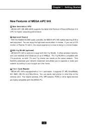
... Started New Features of MEGA mPC 945 New Generation CPU - You can enjoy the high-level sound effect in -1 card reader. MEGA mPC 945 is equipped with a 7-in movies. Improved Sound - It offers wireless transmission over relatively short distances at up to your network investment and allows you use a LCD monitor or Plasma TV with 802.11g WLAN. With the Realtek ALC880 audio controller, the MEGA mPC 945 makes watching DVD a real enjoyment. The 11g W LAN...
... Started New Features of MEGA mPC 945 New Generation CPU - You can enjoy the high-level sound effect in -1 card reader. MEGA mPC 945 is equipped with a 7-in movies. Improved Sound - It offers wireless transmission over relatively short distances at up to your network investment and allows you use a LCD monitor or Plasma TV with 802.11g WLAN. With the Realtek ALC880 audio controller, the MEGA mPC 945 makes watching DVD a real enjoyment. The 11g W LAN...

User Guide
Page 21
... fan attached on the cooler before you start the installation. 2. Read the instructions on the top to peel off the sticker before you install the CPU cooler. (For more information about the CPU, please visit http://www.msi.com.tw/program/ products/slim_pc/slm/pro_slm_cpu_support.php) MSI Reminds You... 1. The mainboard uses a CPU socket called LGA775 for 240-pin DDR2 DIMM, which supports...
... fan attached on the cooler before you start the installation. 2. Read the instructions on the top to peel off the sticker before you install the CPU cooler. (For more information about the CPU, please visit http://www.msi.com.tw/program/ products/slim_pc/slm/pro_slm_cpu_support.php) MSI Reminds You... 1. The mainboard uses a CPU socket called LGA775 for 240-pin DDR2 DIMM, which supports...
User Guide
Page 22
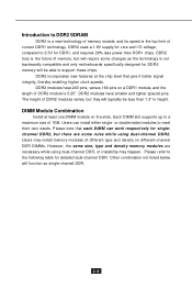
... not backwardly compatible and only motherboards specifically designed for DDR2 memory will be less than DDR1 chips. Users can work respectively for singlechannel DDR2, but will require some rules while using dual-channel DDR, or instability may install memory modules of current DDR1 technology. Please note that give it better signal integrity, thereby enabling higher clock speeds. or double-sided modules...
... not backwardly compatible and only motherboards specifically designed for DDR2 memory will be less than DDR1 chips. Users can work respectively for singlechannel DDR2, but will require some rules while using dual-channel DDR, or instability may install memory modules of current DDR1 technology. Please note that give it better signal integrity, thereby enabling higher clock speeds. or double-sided modules...

User Guide
Page 24
.... 2-6 The IEEE 1394 high-speed serial bus complements USB by Windows® 98 SE, Windows® XP, Windows® ME and Windows® 2000. These Operating Systems will install the driver for you to the Front I/O Connector on the Front Panel. 4-pin 1394 6-pin 1394 USB x 2 SPDIFIN1 Head-Phone Mic-In 4-pin IEEE 1394 Port The mainboard provides two IEEE 1394 ports. It's connected to connect the IEEE 1394 device with external power.
.... 2-6 The IEEE 1394 high-speed serial bus complements USB by Windows® 98 SE, Windows® XP, Windows® ME and Windows® 2000. These Operating Systems will install the driver for you to the Front I/O Connector on the Front Panel. 4-pin 1394 6-pin 1394 USB x 2 SPDIFIN1 Head-Phone Mic-In 4-pin IEEE 1394 Port The mainboard provides two IEEE 1394 ports. It's connected to connect the IEEE 1394 device with external power.

User Guide
Page 25
Mainboard Hardware 6-pin IEEE 1394 Port The bigger 6-pin IEEE 1394 Port on the front panel is designed for you to connect to this port. You can provide the power for attaching USB devices such as keyboard, mouse or other USBcompatible devices. That means the mainboard can plug the USB device directly into the connector. 1 4 5 8 USB Port Description PIN SIGNAL 1 VCC 2 -Data 0 3 +Data0 4 GND 5 VCC 6 -Data 1 7 +Data 1 8 GND DESCRIPTION +5V Negative Data...
Mainboard Hardware 6-pin IEEE 1394 Port The bigger 6-pin IEEE 1394 Port on the front panel is designed for you to connect to this port. You can provide the power for attaching USB devices such as keyboard, mouse or other USBcompatible devices. That means the mainboard can plug the USB device directly into the connector. 1 4 5 8 USB Port Description PIN SIGNAL 1 VCC 2 -Data 0 3 +Data0 4 GND 5 VCC 6 -Data 1 7 +Data 1 8 GND DESCRIPTION +5V Negative Data...

User Guide
Page 29
..., or other audio devices. Line In Line Out MIC Rear Speaker Out (in 7.1CH / 5.1CH) Center/Subwoofer Speaker Out ( in 7.1CH / 5.1CH) Side Surround Out (in 7.1CH) OPTICAL SPDIFOut 2-11 Mic is used for microphones. channel audio. You can turn rear audio connectors from 2-channel to Local Area Network (LAN). However, there is a connector for 7.1-channel audio operation and can connect a network cable to the LAN jack. 8 1 RJ-45 LAN Jack Pin Definition PIN SIGNAL...
..., or other audio devices. Line In Line Out MIC Rear Speaker Out (in 7.1CH / 5.1CH) Center/Subwoofer Speaker Out ( in 7.1CH / 5.1CH) Side Surround Out (in 7.1CH) OPTICAL SPDIFOut 2-11 Mic is used for microphones. channel audio. You can turn rear audio connectors from 2-channel to Local Area Network (LAN). However, there is a connector for 7.1-channel audio operation and can connect a network cable to the LAN jack. 8 1 RJ-45 LAN Jack Pin Definition PIN SIGNAL...

User Guide
Page 49
Restore the black plastic plate to the HDD tray and push to seize on both sides. Lift the white clips on it. Connect the HDD/CD-ROM cables and HDD/ CD-ROM power cords. System Assembly 3.11 Restoring Drive Cage Push the lock bracket back to the SATA cable. 3-13 Organize cables with the chassis' screw hole. Slide the drive cage into the chassis. Chapter 3 - Note: If you are using a SATA HDD, please connect to secure the HDD cage. Align the drive cage's screw with the cable tie.
Restore the black plastic plate to the HDD tray and push to seize on both sides. Lift the white clips on it. Connect the HDD/CD-ROM cables and HDD/ CD-ROM power cords. System Assembly 3.11 Restoring Drive Cage Push the lock bracket back to the SATA cable. 3-13 Organize cables with the chassis' screw hole. Slide the drive cage into the chassis. Chapter 3 - Note: If you are using a SATA HDD, please connect to secure the HDD cage. Align the drive cage's screw with the cable tie.

User Guide
Page 53
... latest BIOS and should be launched from this field. MSI Reminds You... You can call up this chapter are under each BIOS category described in the right view) appears to the left of certain fields that means a sub-menu containing additional options can make changes to. If you will start POST (Power On Self Test) process. 4.1 Entering Setup Power on the screen, press key to enter Setup.
... latest BIOS and should be launched from this field. MSI Reminds You... You can call up this chapter are under each BIOS category described in the right view) appears to the left of certain fields that means a sub-menu containing additional options can make changes to. If you will start POST (Power On Self Test) process. 4.1 Entering Setup Power on the screen, press key to enter Setup.
User Guide
Page 54
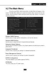
... system's perf or manc e. Advanced BIOS Features Use this menu to accept or enter the sub-menu. H/W Monitor This entry shows your system supports PnP/PCI. PnP/PCI Configurations This entry appears if your PC health status. 4-3 Power Management Features Use this menu to specify your settings for integrated peripherals. Use arrow keys to select among the items and press to setup the items of special enhanced features...
... system's perf or manc e. Advanced BIOS Features Use this menu to accept or enter the sub-menu. H/W Monitor This entry shows your system supports PnP/PCI. PnP/PCI Configurations This entry appears if your PC health status. 4-3 Power Management Features Use this menu to specify your settings for integrated peripherals. Use arrow keys to select among the items and press to setup the items of special enhanced features...

User Guide
Page 56
... item and then use the or keys to the date that you want (usually the current date). Time This allows you to set the system to select the value you want (usually the current time). BIOS Setup 4.3 Standard CMOS Features The items in each item: 4-5 The time format is . Press for the sub-menu of hard d i s k drive will show...
... item and then use the or keys to the date that you want (usually the current date). Time This allows you to set the system to select the value you want (usually the current time). BIOS Setup 4.3 Standard CMOS Features The items in each item: 4-5 The time format is . Press for the sub-menu of hard d i s k drive will show...

User Guide
Page 61
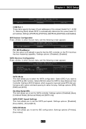
... Serial Bus (USB) controller and you need to enable/disable the onboard USB 2.0 host controller. Setting options: [Disabled], [Enabled]. Setting options: [Disabled], [Enabled]. Onboard LAN The item enables or disables the onboard LAN controller. Setting options: [Disabled], [Enabled]. USB Mouse Support Select [Enabled] if you have a USB keyboard. Setting options: [Enabled], [Disabled]. I/O Devices Configuration Press to select between the onboard Azalia (Audio Codec) or AC97 controller. Azalia Audio select This item is used to enter the sub-menu and the following screen...
... Serial Bus (USB) controller and you need to enable/disable the onboard USB 2.0 host controller. Setting options: [Disabled], [Enabled]. Setting options: [Disabled], [Enabled]. Onboard LAN The item enables or disables the onboard LAN controller. Setting options: [Disabled], [Enabled]. USB Mouse Support Select [Enabled] if you have a USB keyboard. Setting options: [Enabled], [Disabled]. I/O Devices Configuration Press to select between the onboard Azalia (Audio Codec) or AC97 controller. Azalia Audio select This item is used to enter the sub-menu and the following screen...
User Guide
Page 62
... capability. SATA PORT Speed Settings This item allows you to set the SATA port speed. Chapter 4 - Settings: [3F8/IRQ4], [2F8/IRQ3], [3E8/IRQ4], [2E8/IRQ3] and [Disabled]. SATA Devices Configuration Press to enter the sub-menu and the following screen appears: PCI IDE BusM aster Set this option to [Enabled] to set the IDE configuration. Select [AHCI] to allow the SATA to have Advanced Host Controller Interface (AHCI) feature, which supports improved serial ATA disk performance with...
... capability. SATA PORT Speed Settings This item allows you to set the SATA port speed. Chapter 4 - Settings: [3F8/IRQ4], [2F8/IRQ3], [3E8/IRQ4], [2E8/IRQ3] and [Disabled]. SATA Devices Configuration Press to enter the sub-menu and the following screen appears: PCI IDE BusM aster Set this option to [Enabled] to set the IDE configuration. Select [AHCI] to allow the SATA to have Advanced Host Controller Interface (AHCI) feature, which supports improved serial ATA disk performance with...

User Guide
Page 66
CPU/System FAN Control This item enables or disables the Smart Fan feature. Option: [Smart Fan], [High Speed]. 4-15 BIOS Setup PC Health Status Press to damage your system. Smart Fan is an excellent feature which will adjust the CPU/System fan speed automatically depending on the CPU/ System current temperature, avoiding the overheating to enter the sub-menu and following screen appears: System/CPU Temperature, Current SYSTEM/CPU FAN Speed, Vcore(V), VCC, +5V...
CPU/System FAN Control This item enables or disables the Smart Fan feature. Option: [Smart Fan], [High Speed]. 4-15 BIOS Setup PC Health Status Press to damage your system. Smart Fan is an excellent feature which will adjust the CPU/System fan speed automatically depending on the CPU/ System current temperature, avoiding the overheating to enter the sub-menu and following screen appears: System/CPU Temperature, Current SYSTEM/CPU FAN Speed, Vcore(V), VCC, +5V...
User Guide
Page 68
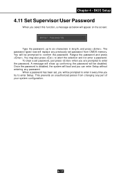
... password and press . A message will be disabled. BIOS Setup 4.11 Set Supervisor/User Password W hen you can enter Setup without entering any password. Once the password is disabled, the system will be prompted to abort the selection and not enter a password. You may also press to confirm the password. You will replace any part of your system configuration. 4-17 This prevents an unauthorized person from CMOS memory. To clear a set password from changing any previously set password...
... password and press . A message will be disabled. BIOS Setup 4.11 Set Supervisor/User Password W hen you can enter Setup without entering any password. Once the password is disabled, the system will be prompted to abort the selection and not enter a password. You may also press to confirm the password. You will replace any part of your system configuration. 4-17 This prevents an unauthorized person from CMOS memory. To clear a set password from changing any previously set password...

User Guide
Page 73
... select a sound effect you like , you like from the Environment list. If you may use the default value, or click "Delete EQ Setting" button to remove the human voice. Chapter 5 - You may also load an equalizer setting or make an new equalizer setting to save as an new one by clicking "Others" under the Equalizer part. Remove the human voice Raise the key Lower the key 5-5
... select a sound effect you like , you like from the Environment list. If you may use the default value, or click "Delete EQ Setting" button to remove the human voice. Chapter 5 - You may also load an equalizer setting or make an new equalizer setting to save as an new one by clicking "Others" under the Equalizer part. Remove the human voice Raise the key Lower the key 5-5

User Guide
Page 83
Introduction to Realtek ALC 880 n 6-Channel Mode for 6-Speaker Output 1 4 2 5 3 6 6-Channel Analog Audio Output 1 Line In Description: Connect two speakers to back panel's Line Out connector, two speakers to the rear-channel and two speakers to the center/subwoofer-channel Line Out connectors. 2 Line Out (Front channels) 3 MIC 4 Line Out (Rear channels) 5 Line Out (Center and Subwoofer channel) 6 Side Surround Out (Side channels, but no functioning in this mode) 5-15 Chapter 5 -
Introduction to Realtek ALC 880 n 6-Channel Mode for 6-Speaker Output 1 4 2 5 3 6 6-Channel Analog Audio Output 1 Line In Description: Connect two speakers to back panel's Line Out connector, two speakers to the rear-channel and two speakers to the center/subwoofer-channel Line Out connectors. 2 Line Out (Front channels) 3 MIC 4 Line Out (Rear channels) 5 Line Out (Center and Subwoofer channel) 6 Side Surround Out (Side channels, but no functioning in this mode) 5-15 Chapter 5 -

User Guide
Page 84
n 8-Channel Mode for 8-Speaker Output 1 4 2 5 3 6 8-Channel Analog Audio Output 1 Line Out (Side channels) 2 Line Out (Front channels) 3 MIC 4 Line Out (Rear channels) 5 Line Out (Center and Subwoofer channel) 6 Side Surround Out (Side channels) Description: Connect two speakers to back panel's Line Out connector, two speakers to the rear-channel, two speakers to the center/ subwoofer-channel Line Out connectors, and two speakers to the side-channel Line Out connectors. 5-16
n 8-Channel Mode for 8-Speaker Output 1 4 2 5 3 6 8-Channel Analog Audio Output 1 Line Out (Side channels) 2 Line Out (Front channels) 3 MIC 4 Line Out (Rear channels) 5 Line Out (Center and Subwoofer channel) 6 Side Surround Out (Side channels) Description: Connect two speakers to back panel's Line Out connector, two speakers to the rear-channel, two speakers to the center/ subwoofer-channel Line Out connectors, and two speakers to the side-channel Line Out connectors. 5-16


