User Guide
Page 5
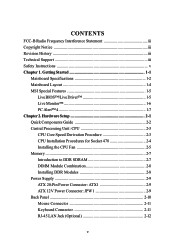
CONTENTS FCC-B Radio Frequency Interference Statement iii Copyright Notice iii Revision History iii Technical Support iii Safety Instructions v Chapter 1. Getting Started 1-1 Mainboard Specifications 1-2 Mainboard Layout 1-4 MSI Special Features 1-5 Live BIOS™/Live Driver 1-5 Live Monitor 1-6 PC Alert™ 4 1-7 Chapter 2. Hardware Setup 2-1 Quick Components Guide 2-2 Central Processing Unit: CPU 2-3 CPU Core Speed ...
CONTENTS FCC-B Radio Frequency Interference Statement iii Copyright Notice iii Revision History iii Technical Support iii Safety Instructions v Chapter 1. Getting Started 1-1 Mainboard Specifications 1-2 Mainboard Layout 1-4 MSI Special Features 1-5 Live BIOS™/Live Driver 1-5 Live Monitor 1-6 PC Alert™ 4 1-7 Chapter 2. Hardware Setup 2-1 Quick Components Guide 2-2 Central Processing Unit: CPU 2-3 CPU Core Speed ...
User Guide
Page 9
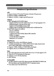
...ports - 2 channel Ultra ATA/100 Bus Master IDE controller - SMBus 2.0 support - 2 serial ATA Host Controllers - h Supports 3.3v/5v PCI bus Interface. h Intel® ICH5 chipset (421 mBGA) - Integrated LAN controller Main Memory h Supports four 64-bit wide DDR data channels h Available bandwidth up to 3.2GB/s ...) for single-channel mode and 8.4 GB/s (DDR 400) for Intel® Pentium 4 (Socket 478) processor h Supports 533MHz or 800MHz FSB h Supports 3.06GHz or higher speed P4 processor Chipsets h Intel® Springdale-865G/865PE chipset - h Can connect up to four IDE...
...ports - 2 channel Ultra ATA/100 Bus Master IDE controller - SMBus 2.0 support - 2 serial ATA Host Controllers - h Supports 3.3v/5v PCI bus Interface. h Intel® ICH5 chipset (421 mBGA) - Integrated LAN controller Main Memory h Supports four 64-bit wide DDR data channels h Available bandwidth up to 3.2GB/s ...) for single-channel mode and 8.4 GB/s (DDR 400) for Intel® Pentium 4 (Socket 478) processor h Supports 533MHz or 800MHz FSB h Supports 3.06GHz or higher speed P4 processor Chipsets h Intel® Springdale-865G/865PE chipset - h Can connect up to four IDE...

User Guide
Page 10
... BIOS provides "Plug & Play" BIOS which records your mainboard specifications. Meet PC2001 audio performance requirement - Supports 10Mb/s and 100Mb/s auto-negotiation operation - Compliant with AC97 v2.2 spec. - Can support SPDIF Out via bracket only On-Board LAN h Intel82562EZ - Dimension h M-ATX Form Factor: 24.5 cm...(L) x 24.5 cm (W) Mounting h 6 mounting holes 1-3 Getting Started On-Board Peripherals h On-Board Peripherals include: - 1 floppy port supports 2 FDD with 360K, 720K, 1.2M, 1.44M and 2.88 Mbytes. - 1 serial port, 1 VGA port (865G) or 2 serial ports (865PE) - 1 ...
... BIOS provides "Plug & Play" BIOS which records your mainboard specifications. Meet PC2001 audio performance requirement - Supports 10Mb/s and 100Mb/s auto-negotiation operation - Compliant with AC97 v2.2 spec. - Can support SPDIF Out via bracket only On-Board LAN h Intel82562EZ - Dimension h M-ATX Form Factor: 24.5 cm...(L) x 24.5 cm (W) Mounting h 6 mounting holes 1-3 Getting Started On-Board Peripherals h On-Board Peripherals include: - 1 floppy port supports 2 FDD with 360K, 720K, 1.2M, 1.44M and 2.88 Mbytes. - 1 serial port, 1 VGA port (865G) or 2 serial ports (865PE) - 1 ...

User Guide
Page 12
... BIOS/driver version throughout the Web site. z Live Utility - If the product you purchased does not support any of the screen. z Live BIOS - z Live VGA Driver - Getting Started MSI Special Features Live BIOS™/Live Driver™ The Live BIOS™/Live Driver™ is displayed.... Updates the BIOS online. Updates the drivers online. Double click the "MSI Live Update 2" icon, and the following screen will appear on the leftmost pane of the functions listed above, a "sorry" message is a...
... BIOS/driver version throughout the Web site. z Live Utility - If the product you purchased does not support any of the screen. z Live BIOS - z Live VGA Driver - Getting Started MSI Special Features Live BIOS™/Live Driver™ The Live BIOS™/Live Driver™ is displayed.... Updates the BIOS online. Updates the drivers online. Double click the "MSI Live Update 2" icon, and the following screen will appear on the leftmost pane of the functions listed above, a "sorry" message is a...
User Guide
Page 15
... item has been changed, please close the PC Alert 4 program for the new settings to . Items shown on PC Alert 4 vary depending on your mainboard supports AMD Athlon™ XP CPU. 2. Cute MSI Reminds You... 1.
... item has been changed, please close the PC Alert 4 program for the new settings to . Items shown on PC Alert 4 vary depending on your mainboard supports AMD Athlon™ XP CPU. 2. Cute MSI Reminds You... 1.

User Guide
Page 18
.... CPU Core Speed Derivation Procedure CPU Clock multiplied by Core/Bus ratio equals the CPU core speed. Hardware Setup Central Processing Unit: CPU The mainboard supports Intel® Pentium® 4/Celeron Northwood/Prescott processor in the 478 pin package.
.... CPU Core Speed Derivation Procedure CPU Clock multiplied by Core/Bus ratio equals the CPU core speed. Hardware Setup Central Processing Unit: CPU The mainboard supports Intel® Pentium® 4/Celeron Northwood/Prescott processor in the 478 pin package.
User Guide
Page 21
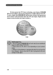
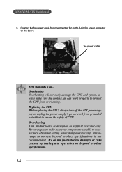
However, please make sure the cooling fan can work properly to protect the CPU from grounded outlet first to support overclocking. Any attempt to operate beyond product specifications. 2-6 MS-6743 M-ATX Mainboard 5. Replacing the CPU While replacing the CPU, always turn off the ATX power ... This motherboard is not recommended. Connect the fan power cable from the mounted fan to tolerate such abnormal setting, while doing overclocking. fan power cable MSI Reminds You...
However, please make sure the cooling fan can work properly to protect the CPU from grounded outlet first to support overclocking. Any attempt to operate beyond product specifications. 2-6 MS-6743 M-ATX Mainboard 5. Replacing the CPU While replacing the CPU, always turn off the ATX power ... This motherboard is not recommended. Connect the fan power cable from the mounted fan to tolerate such abnormal setting, while doing overclocking. fan power cable MSI Reminds You...

User Guide
Page 22
... DDR DIMM slots (DDR 1~2). High memory bandwidth makes DDR an ideal solution for 184-pin DDR SDRAM DIMM (Double In-Line Memory Module) modules and supports the memory size up to 2GB. DIMM 1 DIMM 2 DIMM 3 DIMM 4 Hardware Setup Memory The mainboard provides 2 slots for high performance PC, workstations and servers. 2-7 Introduction...
... DDR DIMM slots (DDR 1~2). High memory bandwidth makes DDR an ideal solution for 184-pin DDR SDRAM DIMM (Double In-Line Memory Module) modules and supports the memory size up to 2GB. DIMM 1 DIMM 2 DIMM 3 DIMM 4 Hardware Setup Memory The mainboard provides 2 slots for high performance PC, workstations and servers. 2-7 Introduction...

User Guide
Page 23
... any order. Memory modules can barely see the golden finger if the module is deeply inserted in the socket. 2-8 Volt Notch MSI Reminds You... MS-6743 M-ATX Mainboard DIMM Module Combination Install at each side of module. You can be installed on the memory...slot will only fit in any combination as follows: Slot Memory Module DIMM 1 S/D (Bank 0 & 1) DIMM 2 S/D (Bank 2 & 3) Maximum System Memory Supported Total Memory 64MB~1GB 64MB~1GB 64MB~2GB S: Single Side D: Double Side Installing DDR Modules 1. Insert the DIMM memory module vertically into the DIMM slot...
... any order. Memory modules can barely see the golden finger if the module is deeply inserted in the socket. 2-8 Volt Notch MSI Reminds You... MS-6743 M-ATX Mainboard DIMM Module Combination Install at each side of module. You can be installed on the memory...slot will only fit in any combination as follows: Slot Memory Module DIMM 1 S/D (Bank 0 & 1) DIMM 2 S/D (Bank 2 & 3) Maximum System Memory Supported Total Memory 64MB~1GB 64MB~1GB 64MB~2GB S: Single Side D: Double Side Installing DDR Modules 1. Insert the DIMM memory module vertically into the DIMM slot...

User Guide
Page 24
... 17 8 PW_OK 18 9 5V_SB 19 10 12V 20 SIGNAL 3.3V -12V GND PS_ON GND GND GND -5V 5V 5V 2-9 Hardware Setup Power Supply The mainboard supports ATX power supply for the power system. Then push down the power supply firmly into the connector. ATX 12V Power Connector: JPW1 This 12V power...
... 17 8 PW_OK 18 9 5V_SB 19 10 12V 20 SIGNAL 3.3V -12V GND PS_ON GND GND GND -5V 5V 5V 2-9 Hardware Setup Power Supply The mainboard supports ATX power supply for the power system. Then push down the power supply firmly into the connector. ATX 12V Power Connector: JPW1 This 12V power...

User Guide
Page 30
Hardware Setup Parallel Port Connector: LPT1 The mainboard provides a 25-pin female centronic connector as LPT. A parallel port is a standard printer port that supports Enhanced Parallel Port (EPP) and Extended Capabilities Parallel Port (ECP) mode. 13 1 25 14 Pin Definition PIN SIGNAL DESCRIPTION 1 STROBE Strobe 2 DATA0 Data0 3 DATA1 Data1 4 ...
Hardware Setup Parallel Port Connector: LPT1 The mainboard provides a 25-pin female centronic connector as LPT. A parallel port is a standard printer port that supports Enhanced Parallel Port (EPP) and Extended Capabilities Parallel Port (ECP) mode. 13 1 25 14 Pin Definition PIN SIGNAL DESCRIPTION 1 STROBE Strobe 2 DATA0 Data0 3 DATA1 Data1 4 ...

User Guide
Page 31
MS-6743 M-ATX Mainboard Connectors The mainboard provides connectors to connect to FDD, IDE HDD, case, modem, LAN, USB Ports, IR module and CPU/System/Power Supply FAN. Floppy Disk Drive Connector: FDD1 The mainboard provides a standard floppy disk drive connector that supports 360K, 720K, 1.2M, 1.44M and 2.88M floppy disk types. FDD1 2-16
MS-6743 M-ATX Mainboard Connectors The mainboard provides connectors to connect to FDD, IDE HDD, case, modem, LAN, USB Ports, IR module and CPU/System/Power Supply FAN. Floppy Disk Drive Connector: FDD1 The mainboard provides a standard floppy disk drive connector that supports 360K, 720K, 1.2M, 1.44M and 2.88M floppy disk types. FDD1 2-16
User Guide
Page 33
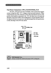
SENSOR +12V GND SYSTEM_FAN GND +12V SENSOR CPU_FAN MSI Reminds You... When connecting the wire to GND. MS-6743 M-ATX Mainboard Fan Power Connectors: CPU_FAN/SYSTEM_FAN The CPU_FAN (processor fan), SYSTEM_FAN1 (system fan) support system cooling fan with speed sensor to take note that the red wire is ... the +12V, the black wire is Ground and should be connected to the connectors, always take advantage of the CPU fan control. It supports three-pin head connector. Always consult the vendors for proper CPU cooling fan. 2-18 If the mainboard has a System Hardware Monitor chipset on...
SENSOR +12V GND SYSTEM_FAN GND +12V SENSOR CPU_FAN MSI Reminds You... When connecting the wire to GND. MS-6743 M-ATX Mainboard Fan Power Connectors: CPU_FAN/SYSTEM_FAN The CPU_FAN (processor fan), SYSTEM_FAN1 (system fan) support system cooling fan with speed sensor to take note that the red wire is ... the +12V, the black wire is Ground and should be connected to the connectors, always take advantage of the CPU fan control. It supports three-pin head connector. Always consult the vendors for proper CPU cooling fan. 2-18 If the mainboard has a System Hardware Monitor chipset on...

User Guide
Page 37
Each Serial ATA connector can connect to Serial ATA Raid manual for detail software installation procedure. Both connectors are fully compliant with Serial ATA 1.0 specifications. Please refer to 1 hard disk device. Each supports 1st generation serial ATA data rates of 150 MB/s. SATA2 SATA1 SATA1 & SATA2 Pin Definition PIN SIGNAL 1 GND 3 TXN 5 RXN 7 GND PIN SIGNAL 2 TXP 4 GND 6 RXP 2-22 MS-6743 M-ATX Mainboard Serial ATA Connectors: SATA1 / SATA2 The mainboard has dual high-speed Serial ATA interface connectors, SATA1 & SATA2.
Each Serial ATA connector can connect to Serial ATA Raid manual for detail software installation procedure. Both connectors are fully compliant with Serial ATA 1.0 specifications. Please refer to 1 hard disk device. Each supports 1st generation serial ATA data rates of 150 MB/s. SATA2 SATA1 SATA1 & SATA2 Pin Definition PIN SIGNAL 1 GND 3 TXN 5 RXN 7 GND PIN SIGNAL 2 TXP 4 GND 6 RXP 2-22 MS-6743 M-ATX Mainboard Serial ATA Connectors: SATA1 / SATA2 The mainboard has dual high-speed Serial ATA interface connectors, SATA1 & SATA2.

User Guide
Page 44
... Slots The motherboard provides one AGP 8x slot. PCI (Peripheral Component Interconnect) Slots The PCI slots allow you unplug the power supply first. The mainboard supports one AGP slot and three 32-bit PCI bus slots. AGP Slot PCI Slots CNR Slot AGP (Accelerated Graphics Port) Slot The AGP slot allows...
... Slots The motherboard provides one AGP 8x slot. PCI (Peripheral Component Interconnect) Slots The PCI slots allow you unplug the power supply first. The mainboard supports one AGP slot and three 32-bit PCI bus slots. AGP Slot PCI Slots CNR Slot AGP (Accelerated Graphics Port) Slot The AGP slot allows...
User Guide
Page 49
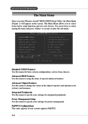
... This entry appears if your system's performance. Advanced BIOS Features Use this menu to change the values in the chipset registers and optimize your system supports PnP/PCI. 3-4 Use arrow keys to select among the items and press to setup the items of special enhanced features. Integrated Peripherals Use this menu...
... This entry appears if your system's performance. Advanced BIOS Features Use this menu to change the values in the chipset registers and optimize your system supports PnP/PCI. 3-4 Use arrow keys to select among the items and press to setup the items of special enhanced features. Integrated Peripherals Use this menu...
User Guide
Page 52
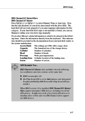
..., there will not work properly if you enter improper information for details.) When BIOS version 1.0 is installed, IDE Channel 0/1 Master/ Slave support maximum 4 IDE devices, including two Serial ATA devices. Cylinder Number of the landing zone. Precomp Write precompensation. BIOS Setup IDE Channel 0/1 ...Press PgUp/ or PgDn/ to Auto (please refer Integrated Peripherals/OnChip IDE Device/On-Chip Serial ATA for this category. This informa- MSI Reminds You... The hard disk will be only two IDE Channel left to define your drive must match with the drive table. IDE...
..., there will not work properly if you enter improper information for details.) When BIOS version 1.0 is installed, IDE Channel 0/1 Master/ Slave support maximum 4 IDE devices, including two Serial ATA devices. Cylinder Number of the landing zone. Precomp Write precompensation. BIOS Setup IDE Channel 0/1 ...Press PgUp/ or PgDn/ to Auto (please refer Integrated Peripherals/OnChip IDE Device/On-Chip Serial ATA for this category. This informa- MSI Reminds You... The hard disk will be only two IDE Channel left to define your drive must match with the drive table. IDE...

User Guide
Page 55
... boot from LS-120 drive. MSI Reminds You... HDD-1 The system will boot from the CD-ROM. HDD-2 The system will boot from USB-interfaced floppy drive. CDROM The system will boot from floppy drive. and *OS: An operating system that supports HT Technology and has it enabled...; LAN The system will boot from the third HDD. The settings are: Floppy The system will boot from ATAPI ZIP drive. HDD-3 The system will boot from the Network drive. MS-6743 M-ATX Mainboard MSI Reminds You... ZIP100...
... boot from LS-120 drive. MSI Reminds You... HDD-1 The system will boot from the CD-ROM. HDD-2 The system will boot from USB-interfaced floppy drive. CDROM The system will boot from floppy drive. and *OS: An operating system that supports HT Technology and has it enabled...; LAN The system will boot from the third HDD. The settings are: Floppy The system will boot from ATAPI ZIP drive. HDD-3 The system will boot from the Network drive. MS-6743 M-ATX Mainboard MSI Reminds You... ZIP100...

User Guide
Page 57
... FDC Controller in APIC mode. Settings: 1.4, 1.1. S.M.A.R.T is used for WIN 95 For compatibility with Windows 95 logo certification, select Yes to select the MPS version supported by your operating system. Due to compliance with PC2001 design guide, the system is powered on or when end users try to run in the...
... FDC Controller in APIC mode. Settings: 1.4, 1.1. S.M.A.R.T is used for WIN 95 For compatibility with Windows 95 logo certification, select Yes to select the MPS version supported by your operating system. Due to compliance with PC2001 design guide, the system is powered on or when end users try to run in the...

User Guide
Page 61
Setting options: Disabled, Enabled. 3-16 If your IDE hard drive supports block mode (most new drives do), select [Enabled] for automatic detection of the optimal number of block read /write. MS-6743 M-ATX Mainboard Integrated Peripherals OnChip IDE Device Press to enter the sub-menu and the following screen appears: IDE HDD Block Mode Block mode is also called block transfer, multiple commands, or multiple sector read /write per sector the drive can support.
Setting options: Disabled, Enabled. 3-16 If your IDE hard drive supports block mode (most new drives do), select [Enabled] for automatic detection of the optimal number of block read /write. MS-6743 M-ATX Mainboard Integrated Peripherals OnChip IDE Device Press to enter the sub-menu and the following screen appears: IDE HDD Block Mode Block mode is also called block transfer, multiple commands, or multiple sector read /write per sector the drive can support.
