User Guide
Page 5
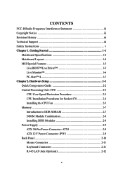
... 2-5 Memory 2-7 Introduction to DDR SDRAM 2-7 DIMM Module Combination 2-8 Installing DDR Modules 2-8 Power Supply 2-9 ATX 20-Pin Power Connector: ATX1 2-9 ATX 12V Power Connector: JPW1 2-9 Back Panel 2-10 Mouse Connector 2-11 Keyboard Connector 2-11 RJ-45 LAN Jack (Optional 2-12 v CONTENTS FCC-B Radio Frequency Interference Statement iii Copyright Notice iii Revision History iii Technical Support iii Safety Instructions v Chapter 1. Getting Started 1-1 Mainboard Specifications 1-2 Mainboard Layout 1-4 MSI Special Features 1-5 Live BIOS™/Live Driver 1-5 Live Monitor...
... 2-5 Memory 2-7 Introduction to DDR SDRAM 2-7 DIMM Module Combination 2-8 Installing DDR Modules 2-8 Power Supply 2-9 ATX 20-Pin Power Connector: ATX1 2-9 ATX 12V Power Connector: JPW1 2-9 Back Panel 2-10 Mouse Connector 2-11 Keyboard Connector 2-11 RJ-45 LAN Jack (Optional 2-12 v CONTENTS FCC-B Radio Frequency Interference Statement iii Copyright Notice iii Revision History iii Technical Support iii Safety Instructions v Chapter 1. Getting Started 1-1 Mainboard Specifications 1-2 Mainboard Layout 1-4 MSI Special Features 1-5 Live BIOS™/Live Driver 1-5 Live Monitor...

User Guide
Page 6
... Hard Disk Connectors: IDE1 & IDE2 2-17 Fan Power Connectors: CPU_FAN/SYSTEM_FAN 2-18 CD-In Connector: JCD1 2-19 SPDIF Connector: JSPD1(Optional 2-19 IrDA Infrared Module Header: JIR1 (865PE only 2-20 Chassis Intrusion Switch Connector: JCI1 2-20 Front Panel Connector: JFP1 2-21 Serial ATA Connectors: SATA1/SATA2 2-22 Front Panel Audio Connector: JAUD1 2-24 Front USB Connectors: JUSB1/JUSB2 2-25 IEEE 1394 Connector: J1394_1 2-26 Jumpers 2-28 Clear CMOS Jumper: JBAT1 2-28 Slots 2-29 AGP (Accelerated Graphics Port) Slots 2-29 PCI...
... Hard Disk Connectors: IDE1 & IDE2 2-17 Fan Power Connectors: CPU_FAN/SYSTEM_FAN 2-18 CD-In Connector: JCD1 2-19 SPDIF Connector: JSPD1(Optional 2-19 IrDA Infrared Module Header: JIR1 (865PE only 2-20 Chassis Intrusion Switch Connector: JCI1 2-20 Front Panel Connector: JFP1 2-21 Serial ATA Connectors: SATA1/SATA2 2-22 Front Panel Audio Connector: JAUD1 2-24 Front USB Connectors: JUSB1/JUSB2 2-25 IEEE 1394 Connector: J1394_1 2-26 Jumpers 2-28 Clear CMOS Jumper: JBAT1 2-28 Slots 2-29 AGP (Accelerated Graphics Port) Slots 2-29 PCI...
User Guide
Page 7
or 6-Channel Audio Function A-18 Troubleshooting T-1 Glossary ...G-1 vii Getting Help 3-3 The Main Menu 3-4 Standard CMOS Features 3-6 Advanced BIOS Features 3-9 Advanced Chipset Features 3-13 Integrated Peripherals 3-16 Power Management Setup 3-23 PNP/PCI Configurations 3-27 PC Health Status 3-29 Frequency/Voltage Control 3-31 Load High Performance/BIOS Setup Defaults 3-33 Set Supervisor/User Password 3-34 Appendix: Using 2-, 4- or 6-Channel Audio Function A-1 Installing C-Media Driver A-2 Hardware Configuration A-4 Software Configuration A-5 Using 2-, 4-
or 6-Channel Audio Function A-18 Troubleshooting T-1 Glossary ...G-1 vii Getting Help 3-3 The Main Menu 3-4 Standard CMOS Features 3-6 Advanced BIOS Features 3-9 Advanced Chipset Features 3-13 Integrated Peripherals 3-16 Power Management Setup 3-23 PNP/PCI Configurations 3-27 PC Health Status 3-29 Frequency/Voltage Control 3-31 Load High Performance/BIOS Setup Defaults 3-33 Set Supervisor/User Password 3-34 Appendix: Using 2-, 4- or 6-Channel Audio Function A-1 Installing C-Media Driver A-2 Hardware Configuration A-4 Software Configuration A-5 Using 2-, 4-

User Guide
Page 28
Hardware Setup VGA Connector The mainboard provides a DB 15-pin female connector to connect a VGA monitor. 5 1 15 11 VGA Connector (DB 15-pin) Pin Signal Description 1 RED 2 GREEN 3 BLUE 4 N/C 5 GND 6 GND 7 GND 8 GND 9 +5V 10 GND 11 N/C 12 SDA 13 Horizontal Sync 14 Vertical Sync 15 SCL Audio Port Connectors Line Out is a connector for microphones. 1/8" Stereo Audio Connectors Line In Line Out MIC 2-13 MIC-In is a connector for external CD player, Tape player, or other audio devices. Line In is used for Speakers or Headphones.
Hardware Setup VGA Connector The mainboard provides a DB 15-pin female connector to connect a VGA monitor. 5 1 15 11 VGA Connector (DB 15-pin) Pin Signal Description 1 RED 2 GREEN 3 BLUE 4 N/C 5 GND 6 GND 7 GND 8 GND 9 +5V 10 GND 11 N/C 12 SDA 13 Horizontal Sync 14 Vertical Sync 15 SCL Audio Port Connectors Line Out is a connector for microphones. 1/8" Stereo Audio Connectors Line In Line Out MIC 2-13 MIC-In is a connector for external CD player, Tape player, or other audio devices. Line In is used for Speakers or Headphones.

User Guide
Page 29
... A/B The mainboard offers two 9-pin male DIN connectors, COM A/B. You can attach a serial mouse or other PCs, and portable devices. Both are 16550A high speed communication ports that send/receive 16 bytes FIFOs. The IEEE1394 high-speed serial bus complements USB by providing enhanced PC connectivity for a wide range of devices, including consumer electronics audio/video (A/V) appliances, storage peripherals, other serial device directly to IEEE1394 devices without external power.
... A/B The mainboard offers two 9-pin male DIN connectors, COM A/B. You can attach a serial mouse or other PCs, and portable devices. Both are 16550A high speed communication ports that send/receive 16 bytes FIFOs. The IEEE1394 high-speed serial bus complements USB by providing enhanced PC connectivity for a wide range of devices, including consumer electronics audio/video (A/V) appliances, storage peripherals, other serial device directly to IEEE1394 devices without external power.
User Guide
Page 32
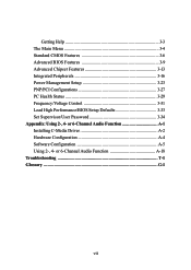
... four hard disk drives, CD-ROM, 120MB Floppy (reserved for jumper setting instructions. 2-17 You can connect up to Slave mode by hard disk vendors for future BIOS) and other devices. If you install two hard disks on cable, you must configure second hard drive to the hard disk documentation supplied by setting its jumper. IDE2 (Secondary IDE Connector) IDE2 can connect a Master and a Slave drive. IDE2 IDE1 IDE1 (Primary IDE Connector) The first hard drive should always be connected to IDE1. Hardware Setup Hard Disk Connectors...
... four hard disk drives, CD-ROM, 120MB Floppy (reserved for jumper setting instructions. 2-17 You can connect up to Slave mode by hard disk vendors for future BIOS) and other devices. If you install two hard disks on cable, you must configure second hard drive to the hard disk documentation supplied by setting its jumper. IDE2 (Secondary IDE Connector) IDE2 can connect a Master and a Slave drive. IDE2 IDE1 IDE1 (Primary IDE Connector) The first hard drive should always be connected to IDE1. Hardware Setup Hard Disk Connectors...
User Guide
Page 49
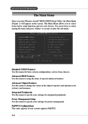
... exit choices. Integrated Peripherals Use this menu to specify your settings for integrated peripherals. Power Management Setup Use this menu to setup the items of special enhanced features. Advanced BIOS Features Use this menu for power management. The Main Menu allows you enter Phoenix-Award® BIOS CMOS Setup Utility, the Main Menu (Figure 1) will appear on the screen. Standard CMOS Features Use this menu to specify your settings for basic system configurations, such as time, date...
... exit choices. Integrated Peripherals Use this menu to specify your settings for integrated peripherals. Power Management Setup Use this menu to setup the items of special enhanced features. Advanced BIOS Features Use this menu for power management. The Main Menu allows you enter Phoenix-Award® BIOS CMOS Setup Utility, the Main Menu (Figure 1) will appear on the screen. Standard CMOS Features Use this menu to specify your settings for basic system configurations, such as time, date...

User Guide
Page 54
... logo on the bootup screen. BIOS Setup Advanced BIOS Features BIOS Virus Warning The item is made, BIOS will display a warning message on screen and beep. Hyper-Threading Technology The processor uses Hyper-Threading technology to set the Virus Warning feature for IDE Hard Disk boot sector protection. Settings: Enabled, Disabled. tings are: Enabled Shows a still image (logo) on the full screen at boot. 3-9 Disabled Shows the POST messages at boot. If the function...
... logo on the bootup screen. BIOS Setup Advanced BIOS Features BIOS Virus Warning The item is made, BIOS will display a warning message on screen and beep. Hyper-Threading Technology The processor uses Hyper-Threading technology to set the Virus Warning feature for IDE Hard Disk boot sector protection. Settings: Enabled, Disabled. tings are: Enabled Shows a still image (logo) on the full screen at boot. 3-9 Disabled Shows the POST messages at boot. If the function...

User Guide
Page 57
... which MPS (Multi-Processor Specification) version to be used to enable or disable the APIC (Advanced Programmable Interrupt Controller). Settings: Enabled and Disabled. When this setting is able to run Setup. Due to compliance with PC2001 design guide, the system is set to Yes, users have to select Disabled for the hard disks. Settings: 1.4, 1.1. Enabling APIC mode will expand available IRQ resources for WIN 95 For compatibility with Windows 95 logo certification...
... which MPS (Multi-Processor Specification) version to be used to enable or disable the APIC (Advanced Programmable Interrupt Controller). Settings: Enabled and Disabled. When this setting is able to run Setup. Due to compliance with PC2001 design guide, the system is set to Yes, users have to select Disabled for the hard disks. Settings: 1.4, 1.1. Enabling APIC mode will expand available IRQ resources for WIN 95 For compatibility with Windows 95 logo certification...

User Guide
Page 63
... Compatible Mode with Serial ATA Port 1 set to Primary Master. 2. Primary Master Compatible Mode with only Serial ATA Enabled and Port 1 set to Secondary Master. 7. Primary Master Compatible Mode with Serial ATA Port 1 set to Secondary Master. 4. MS-6743 M-ATX Mainboard Serial ATA Port 0/1 Mode Select a compatible mode for Port 1 and Port 2 from Award setting to enter the sub-menu and the following screen appears: 3-18 Secondary Master Compatible Mode with only Serial ATA Enabled and Port 1 set...
... Compatible Mode with Serial ATA Port 1 set to Primary Master. 2. Primary Master Compatible Mode with only Serial ATA Enabled and Port 1 set to Secondary Master. 7. Primary Master Compatible Mode with Serial ATA Port 1 set to Secondary Master. 4. MS-6743 M-ATX Mainboard Serial ATA Port 0/1 Mode Select a compatible mode for Port 1 and Port 2 from Award setting to enter the sub-menu and the following screen appears: 3-18 Secondary Master Compatible Mode with only Serial ATA Enabled and Port 1 set...

User Guide
Page 64
.... Onboard LAN Control This setting controls the onboard LAN controller. Onboard 1394 Device This setting controls the onboard 1394 device. AC97 Audio Auto allows the motherboard's BIOS to Disabled. USB 2.0 Controller Set to Enabled if you 're using any USB 2.0 driver installed, such as DOS and SCO Unix. Setting options: Enabled, Disabled. BIOS Setup USB Controller This setting is used to detect whether a modem is used. Setting options: Disabled, Enabled. If you want to use other controller cards to use different controller cards to connect audio connectors, set the field...
.... Onboard LAN Control This setting controls the onboard LAN controller. Onboard 1394 Device This setting controls the onboard 1394 device. AC97 Audio Auto allows the motherboard's BIOS to Disabled. USB 2.0 Controller Set to Enabled if you 're using any USB 2.0 driver installed, such as DOS and SCO Unix. Setting options: Enabled, Disabled. BIOS Setup USB Controller This setting is used to detect whether a modem is used. Setting options: Disabled, Enabled. If you want to use other controller cards to use different controller cards to connect audio connectors, set the field...

User Guide
Page 65
... disk controller (FDD) installed on the system board and you can power on the system. KB Power ON Password If POWER ON Function is set to Hot KEY, you install add-on FDC or the system has no floppy drive, select Disabled in the filed for the PS/2 keyboard to enter the sub-menu and the following screen appears: POWER ON Function This controls how the PS/2 mouse or keyboard can set to Password...
... disk controller (FDD) installed on the system board and you can power on the system. KB Power ON Password If POWER ON Function is set to Hot KEY, you install add-on FDC or the system has no floppy drive, select Disabled in the filed for the PS/2 keyboard to enter the sub-menu and the following screen appears: POWER ON Function This controls how the PS/2 mouse or keyboard can set to Password...

User Guide
Page 70
... Key and Disabled. 3-25 You need to specify the CPU speed (at 12.5% increment. HDD Power Down If HDD activity is turned off button. off . MSI Reminds You... Settings: Disabled, 1 through 15 Min. ters the suspend/sleep mode, but if the button is pressed for more than four seconds, the computer is not detected for "Wake Up On Ring" function. Suspend When you to install a modem card supporting power on /- Options: Enabled, Disabled. CPU THRM...
... Key and Disabled. 3-25 You need to specify the CPU speed (at 12.5% increment. HDD Power Down If HDD activity is turned off button. off . MSI Reminds You... Settings: Disabled, 1 through 15 Min. ters the suspend/sleep mode, but if the button is pressed for more than four seconds, the computer is not detected for "Wake Up On Ring" function. Suspend When you to install a modem card supporting power on /- Options: Enabled, Disabled. CPU THRM...

User Guide
Page 79
... is the Security Option of the setup menu. If set password from changing any part of your system configuration. MS-6743 M-ATX Mainboard Set Supervisor/User Password When you select this function, a message as below will appear on the screen: Type the password, up confirming the password will be prompted to confirm the password. To clear a set password, just press when you can enter Setup without entering any previously set to Setup, password prompt only...
... is the Security Option of the setup menu. If set password from changing any part of your system configuration. MS-6743 M-ATX Mainboard Set Supervisor/User Password When you select this function, a message as below will appear on the screen: Type the password, up confirming the password will be prompted to confirm the password. To clear a set password, just press when you can enter Setup without entering any previously set to Setup, password prompt only...
User Guide
Page 81
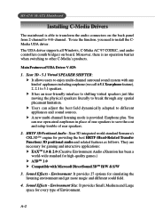
... is no operation barrier when switching to 4-/6-channel. Main Features of Environment. Xear 3D - 5.1 Virtual SPEAKER SHIFTER: h It allows users to save the cost and setup trouble of rear speakers. 2. h Users can use the function, you need to 5.1 speakers. A-2 h A new multi-channel listening mode is provided: Earphone plus. MS-6743 M-ATX Mainboard Installing C-Media Drivers The mainboard is able to transform the audio connectors on board. Sound Effects - To use open-aired earphones...
... is no operation barrier when switching to 4-/6-channel. Main Features of Environment. Xear 3D - 5.1 Virtual SPEAKER SHIFTER: h It allows users to save the cost and setup trouble of rear speakers. 2. h Users can use the function, you need to 5.1 speakers. A-2 h A new multi-channel listening mode is provided: Earphone plus. MS-6743 M-ATX Mainboard Installing C-Media Drivers The mainboard is able to transform the audio connectors on board. Sound Effects - To use open-aired earphones...
User Guide
Page 82
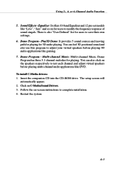
... to complete installation. 4. Sound Effects - Demo Program - Follow the on-screen instructions to adjust your virtual speakers before playing multi-channel audio applications like "Live", "Jazz" and so on C-Media Sound Drivers. 3. Using 2-, 4- To install C-Media drivers: 1. Equalizer: It offers 10-band Equalizer and 12 pre-set models like DVD. Insert the companion CD into the CD-ROM drive. You can also click on the speakers respectively to test each...
... to complete installation. 4. Sound Effects - Demo Program - Follow the on-screen instructions to adjust your virtual speakers before playing multi-channel audio applications like "Live", "Jazz" and so on C-Media Sound Drivers. 3. Using 2-, 4- To install C-Media drivers: 1. Equalizer: It offers 10-band Equalizer and 12 pre-set models like DVD. Insert the companion CD into the CD-ROM drive. You can also click on the speakers respectively to test each...
User Guide
Page 83
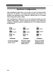
... installing the C-Media drivers, you are listed below: Line In Line Out MIC Line In Line Out MIC 2-Channel In 2-channel configuration, Line Out, Line In and MIC functions all exist. 4-Channel When set to 4-channel configuration, LINE IN function DOES NOT WORK any more. or 6-channel audio setting in the software utility. A-4 To enable 4- or 6-channel audio operation, first connect 4 or 6 speakers to the LINE OUT connectors...
... installing the C-Media drivers, you are listed below: Line In Line Out MIC Line In Line Out MIC 2-Channel In 2-channel configuration, Line Out, Line In and MIC functions all exist. 4-Channel When set to 4-channel configuration, LINE IN function DOES NOT WORK any more. or 6-channel audio setting in the software utility. A-4 To enable 4- or 6-channel audio operation, first connect 4 or 6 speakers to the LINE OUT connectors...
User Guide
Page 95
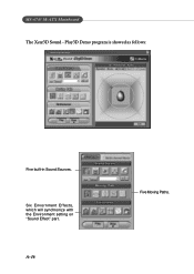
Play3D Demo program is showed as follows: Five built-in Sound Sources. Six Envornment Effects, which will synchronize with the Environment setting on "Sound Effect" part. MS-6743 M-ATX Mainboard The Xear3D Sound - A-16 Five Moving Paths.
Play3D Demo program is showed as follows: Five built-in Sound Sources. Six Envornment Effects, which will synchronize with the Environment setting on "Sound Effect" part. MS-6743 M-ATX Mainboard The Xear3D Sound - A-16 Five Moving Paths.

User Guide
Page 107
... need to set its associated device(s). IRQ conflicts used to connect hard disks, CD-ROMs and tape drives to another without any cables. IRQ (Interrupt Request Line) IRQs are connected by setting a DIP switch. The IDE interface is also called the primary cache. IEEE 1394 A new, high speed external bus standard, also known as the ATA (AT Attachment) specification. It is a standard bus (computer interconnection) architecture that covers...
... need to set its associated device(s). IRQ conflicts used to connect hard disks, CD-ROMs and tape drives to another without any cables. IRQ (Interrupt Request Line) IRQs are connected by setting a DIP switch. The IDE interface is also called the primary cache. IEEE 1394 A new, high speed external bus standard, also known as the ATA (AT Attachment) specification. It is a standard bus (computer interconnection) architecture that covers...
User Guide
Page 108
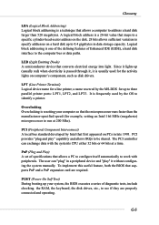
.... PnP (Plug and Play) A set of diagnostic tests, include checking the RAM, the keyboard, the disk drives, etc., to see if they are required. G-5 Since it lights up (usually red) when electricity is passed through it, it without configuring the system manually. LED (Light Emitting Diode) A semiconductor device that supports PnP and a PnP expansion card are properly connected and operating. It is resetting your system, the BIOS executes a series of specifications that...
.... PnP (Plug and Play) A set of diagnostic tests, include checking the RAM, the keyboard, the disk drives, etc., to see if they are required. G-5 Since it lights up (usually red) when electricity is passed through it, it without configuring the system manually. LED (Light Emitting Diode) A semiconductor device that supports PnP and a PnP expansion card are properly connected and operating. It is resetting your system, the BIOS executes a series of specifications that...


