
User Guide
Page 3
.... Trademarks All trademarks are the properties of Microsoft Corporation. Revision History Revision V1.0 V1.1 Revision History First release for PCB 1.x Add 1394 connetor BIOS, add CPU Smart Fan Temperature and CPU Fan Tolerance Value Date April 2003 May 2003 iii
.... Trademarks All trademarks are the properties of Microsoft Corporation. Revision History Revision V1.0 V1.1 Revision History First release for PCB 1.x Add 1394 connetor BIOS, add CPU Smart Fan Temperature and CPU Fan Tolerance Value Date April 2003 May 2003 iii
User Guide
Page 5
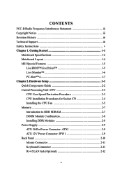
... Quick Components Guide 2-2 Central Processing Unit: CPU 2-3 CPU Core Speed Derivation Procedure 2-3 CPU Installation Procedures for Socket 478 2-4 Installing the CPU Fan 2-5 Memory 2-7 Introduction to DDR SDRAM ...2-7 DIMM Module Combination 2-8 Installing DDR Modules 2-8 Power Supply 2-9 ATX 20-Pin Power Connector: ATX1 2-9 ATX 12V Power Connector: JPW1 2-9 Back Panel 2-10 Mouse Connector 2-11 Keyboard Connector 2-11 RJ-45 LAN Jack (Optional 2-12 v Getting Started 1-1 Mainboard Specifications 1-2 Mainboard Layout 1-4 MSI...
... Quick Components Guide 2-2 Central Processing Unit: CPU 2-3 CPU Core Speed Derivation Procedure 2-3 CPU Installation Procedures for Socket 478 2-4 Installing the CPU Fan 2-5 Memory 2-7 Introduction to DDR SDRAM ...2-7 DIMM Module Combination 2-8 Installing DDR Modules 2-8 Power Supply 2-9 ATX 20-Pin Power Connector: ATX1 2-9 ATX 12V Power Connector: JPW1 2-9 Back Panel 2-10 Mouse Connector 2-11 Keyboard Connector 2-11 RJ-45 LAN Jack (Optional 2-12 v Getting Started 1-1 Mainboard Specifications 1-2 Mainboard Layout 1-4 MSI...
User Guide
Page 9
...) - SMBus 2.0 support - 2 serial ATA Host Controllers - AC'97 2.3 interface - 8 USB 2.0/1.1 ports - 2 channel Ultra ATA/100 Bus Master IDE controller - MS-6743 M-ATX Mainboard Mainboard Specifications CPU h Supports Socket 478 for dual-channel mode h Supports 128Mb, 256Mb or 512Mb DDR technologies h Supports only x8, x16 DDR devices with PIO, Bus Master and...
...) - SMBus 2.0 support - 2 serial ATA Host Controllers - AC'97 2.3 interface - 8 USB 2.0/1.1 ports - 2 channel Ultra ATA/100 Bus Master IDE controller - MS-6743 M-ATX Mainboard Mainboard Specifications CPU h Supports Socket 478 for dual-channel mode h Supports 128Mb, 256Mb or 512Mb DDR technologies h Supports only x8, x16 DDR devices with PIO, Bus Master and...

User Guide
Page 14
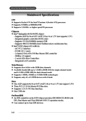
This will show the current CPU temperature. 1-7 Getting Started PC Alert™ 4 The PC AlertTM 4 is abnormal, the program main screen will be immediately shown on the Status Area will continue ... find in red. The utility is just like your PC doctor that can detect the following PC hardware status during real time operation: Ø monitor CPU & system temperatures Ø monitor fan speeds Ø monitor system voltages If one of the items above is a utility you can use the Adjusting Keys to...
This will show the current CPU temperature. 1-7 Getting Started PC Alert™ 4 The PC AlertTM 4 is abnormal, the program main screen will be immediately shown on the Status Area will continue ... find in red. The utility is just like your PC doctor that can detect the following PC hardware status during real time operation: Ø monitor CPU & system temperatures Ø monitor fan speeds Ø monitor system voltages If one of the items above is a utility you can use the Adjusting Keys to...
User Guide
Page 15
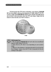
...of each item has been changed, please close the PC Alert 4 program for the new settings to take effect. 1-8 Cute MSI Reminds You... 1. MS-6743 M-ATX Mainboard To better protect the CPU from overheating, a new feature, COOLER XP, has been added to . Whenever the minimum or maximum threshold of AMD Athlon™...; XP CPU. The new feature COOLER XP will show the Cute skin (as shown below) with information about the CPU and chipset. To do so, simply click COOLER XP and the screen will work only if ...
...of each item has been changed, please close the PC Alert 4 program for the new settings to take effect. 1-8 Cute MSI Reminds You... 1. MS-6743 M-ATX Mainboard To better protect the CPU from overheating, a new feature, COOLER XP, has been added to . Whenever the minimum or maximum threshold of AMD Athlon™...; XP CPU. The new feature COOLER XP will show the Cute skin (as shown below) with information about the CPU and chipset. To do so, simply click COOLER XP and the screen will work only if ...

User Guide
Page 16
While doing the installation, be careful in holding the components and follow the installation procedures. 2-1 Also, it provides the instructions on the mainboard. Hardware Setup Chapter 2. Hardware Setup Hardware Setup This chapter tells you how to install the CPU, memory modules, and expansion cards, as well as how to setup the jumpers on connecting the peripheral devices, such as the mouse, keyboard, etc.
While doing the installation, be careful in holding the components and follow the installation procedures. 2-1 Also, it provides the instructions on the mainboard. Hardware Setup Chapter 2. Hardware Setup Hardware Setup This chapter tells you how to install the CPU, memory modules, and expansion cards, as well as how to setup the jumpers on connecting the peripheral devices, such as the mouse, keyboard, etc.

User Guide
Page 18
... your dealer to purchase and install them before turning on the top to prevent overheating. CPU Core Speed Derivation Procedure CPU Clock multiplied by Core/Bus ratio equals the CPU core speed. If you are installing the CPU, make sure the CPU has a heat sink and a cooling fan attached on the computer. The mainboard uses...
... your dealer to purchase and install them before turning on the top to prevent overheating. CPU Core Speed Derivation Procedure CPU Clock multiplied by Core/Bus ratio equals the CPU core speed. If you are installing the CPU, make sure the CPU has a heat sink and a cooling fan attached on the computer. The mainboard uses...

User Guide
Page 19
... likely to move while the lever is being closed, always close the lever. Dot / Cut edge Correct CPU placement O Dot / Cut edge X Incorrect CPU placement Press down firmly into the socket and close the lever with your mainboard. 5. Look for Socket 478 1. Sliding Plate Open Lever 90 ...degree Dot / Cut edge 4. Make sure to raise the lever up to make sure the CPU is correctly installed, the pins should point towards the lever pivot. The CPU can not be completely embedded into the socket. Please note that any violation of the correct installation procedures may...
... likely to move while the lever is being closed, always close the lever. Dot / Cut edge Correct CPU placement O Dot / Cut edge X Incorrect CPU placement Press down firmly into the socket and close the lever with your mainboard. 5. Look for Socket 478 1. Sliding Plate Open Lever 90 ...degree Dot / Cut edge 4. Make sure to raise the lever up to make sure the CPU is correctly installed, the pins should point towards the lever pivot. The CPU can not be completely embedded into the socket. Please note that any violation of the correct installation procedures may...

User Guide
Page 20
...becomes increasingly important. Mount the fan on the motherboard. Follow the instructions below to attach the CPU cooling fan and heatsink on top of the retention mechanism. 4. Locate the CPU and its four clips get wedged in only ONE direction. Position the heatsink onto the retention ...mechanism. 3. Press the two levers down in the holes of the CPU. To dissipate heat, you need to install the Heatsink...
...becomes increasingly important. Mount the fan on the motherboard. Follow the instructions below to attach the CPU cooling fan and heatsink on top of the retention mechanism. 4. Locate the CPU and its four clips get wedged in only ONE direction. Position the heatsink onto the retention ...mechanism. 3. Press the two levers down in the holes of the CPU. To dissipate heat, you need to install the Heatsink...
User Guide
Page 21
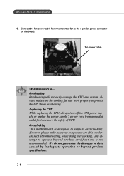
Replacing the CPU While replacing the CPU, always turn off the ATX power supply or unplug the power supply's power cord from grounded outlet first to support overclocking. fan power cable MSI Reminds You... We do not guarantee the damages or risks caused by inadequate ...operation or beyond product specifications is designed to ensure the safety of CPU. Overclocking This motherboard is not recommended. Overheating Overheating will...
Replacing the CPU While replacing the CPU, always turn off the ATX power supply or unplug the power supply's power cord from grounded outlet first to support overclocking. fan power cable MSI Reminds You... We do not guarantee the damages or risks caused by inadequate ...operation or beyond product specifications is designed to ensure the safety of CPU. Overclocking This motherboard is not recommended. Overheating Overheating will...

User Guide
Page 24
... the power supply is used to provide power to the ATX power supply, make sure that no damage will be caused. To connect to the CPU. 2 1 4 3 JPW1 JPW1 Pin Definition PIN SIGNAL 1 GND 2 GND 3 12V 4 12V 10 20 1 11 ATX1 ATX1 Pin Definition PIN SIGNAL PIN 1 3.3V 11 2 3.3V 12 3 GND...
... the power supply is used to provide power to the ATX power supply, make sure that no damage will be caused. To connect to the CPU. 2 1 4 3 JPW1 JPW1 Pin Definition PIN SIGNAL 1 GND 2 GND 3 12V 4 12V 10 20 1 11 ATX1 ATX1 Pin Definition PIN SIGNAL PIN 1 3.3V 11 2 3.3V 12 3 GND...

User Guide
Page 31
FDD1 2-16 Floppy Disk Drive Connector: FDD1 The mainboard provides a standard floppy disk drive connector that supports 360K, 720K, 1.2M, 1.44M and 2.88M floppy disk types. MS-6743 M-ATX Mainboard Connectors The mainboard provides connectors to connect to FDD, IDE HDD, case, modem, LAN, USB Ports, IR module and CPU/System/Power Supply FAN.
FDD1 2-16 Floppy Disk Drive Connector: FDD1 The mainboard provides a standard floppy disk drive connector that supports 360K, 720K, 1.2M, 1.44M and 2.88M floppy disk types. MS-6743 M-ATX Mainboard Connectors The mainboard provides connectors to connect to FDD, IDE HDD, case, modem, LAN, USB Ports, IR module and CPU/System/Power Supply FAN.
User Guide
Page 33
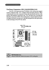
... the mainboard has a System Hardware Monitor chipset on-board, you must use a specially designed fan with +12V. SENSOR +12V GND SYSTEM_FAN GND +12V SENSOR CPU_FAN MSI Reminds You... When connecting the wire to GND. MS-6743 M-ATX Mainboard Fan Power Connectors: CPU_FAN/SYSTEM_FAN The CPU_FAN (processor fan), SYSTEM_FAN1 (system fan) support... positive and should be connected to the +12V, the black wire is Ground and should be connected to the connectors, always take advantage of the CPU fan control. It supports three-pin head connector. Always consult the vendors for proper...
... the mainboard has a System Hardware Monitor chipset on-board, you must use a specially designed fan with +12V. SENSOR +12V GND SYSTEM_FAN GND +12V SENSOR CPU_FAN MSI Reminds You... When connecting the wire to GND. MS-6743 M-ATX Mainboard Fan Power Connectors: CPU_FAN/SYSTEM_FAN The CPU_FAN (processor fan), SYSTEM_FAN1 (system fan) support... positive and should be connected to the +12V, the black wire is Ground and should be connected to the connectors, always take advantage of the CPU fan control. It supports three-pin head connector. Always consult the vendors for proper...

User Guide
Page 53
... adapter used for any error is detected at boot. Video The setting controls the type of the system. CPU Type/BIOS Version/System Memory/Total Memory/ Video Memory (865G only) These items show the CPU type, BIOS version and memory status of floppy drives installed. The system doesn't stop for a keyboard error...
... adapter used for any error is detected at boot. Video The setting controls the type of the system. CPU Type/BIOS Version/System Memory/Total Memory/ Video Memory (865G only) These items show the CPU type, BIOS version and memory status of floppy drives installed. The system doesn't stop for a keyboard error...

User Guide
Page 55
For more information on the bootable devices you have installed. For example, if you to set the sequence of the following platform Components: *CPU: An Intel® Pentium® 4 Processor with HT Technology; *Chipset: An Intel® Chipset that supports HT Technology; *BIOS: A BIOS... that supports HT Technology. MS-6743 M-ATX Mainboard MSI Reminds You... ZIP100 The system will boot from the USB-interfaced CD-ROM. USB-ZIP The system will boot from any USB-interfaced ATAPI ZIP...
For more information on the bootable devices you have installed. For example, if you to set the sequence of the following platform Components: *CPU: An Intel® Pentium® 4 Processor with HT Technology; *Chipset: An Intel® Chipset that supports HT Technology; *BIOS: A BIOS... that supports HT Technology. MS-6743 M-ATX Mainboard MSI Reminds You... ZIP100 The system will boot from the USB-interfaced CD-ROM. USB-ZIP The system will boot from any USB-interfaced ATAPI ZIP...

User Guide
Page 59
... field. Setting options: Enabled, Disabled. Setting options: Disabled, Enabled. When this area is also activated to C7FFFh, resulting in this item to Thermal When the CPU temperature reaches a factory preset level, a thermal monitoring mechanism will be enabled following the appropriate timing delay specified in better video performance. Delay Prior to configure...
... field. Setting options: Enabled, Disabled. Setting options: Disabled, Enabled. When this area is also activated to C7FFFh, resulting in this item to Thermal When the CPU temperature reaches a factory preset level, a thermal monitoring mechanism will be enabled following the appropriate timing delay specified in better video performance. Delay Prior to configure...

User Guide
Page 68
S3-related functions described in memory will be used to save energy. The information stored in this state, no system context is lost (CPU or chipset) and hardware maintains all system context. Sleep State This item specifies the power saving modes for ACPI function. S3/STR The S3 sleep ... restore the system when a "wake up" event occurs. 3-23 Options are available only when your BIOS supports S3 sleep mode. BIOS Setup Power Management Setup MSI Reminds You...
S3-related functions described in memory will be used to save energy. The information stored in this state, no system context is lost (CPU or chipset) and hardware maintains all system context. Sleep State This item specifies the power saving modes for ACPI function. S3/STR The S3 sleep ... restore the system when a "wake up" event occurs. 3-23 Options are available only when your BIOS supports S3 sleep mode. BIOS Setup Power Management Setup MSI Reminds You...

User Guide
Page 70
... numbers) to wake up the system from power saving modes when activity or input signal of the specified hardware peripheral or component is detected. CPU THRM-Throttling The item allows you to which it will be awakened from S3 state. Settings range from S3 This setting allows you press the... USB KB Wake-Up from 12.5% to 87.5% at percentage) to specify the CPU speed (at 12.5% increment. ters the suspend/sleep mode, but if the button is pressed for "Wake Up On Ring" function. MSI Reminds You... Power Button Function This feature allows users to install a modem card ...
... numbers) to wake up the system from power saving modes when activity or input signal of the specified hardware peripheral or component is detected. CPU THRM-Throttling The item allows you to which it will be awakened from S3 state. Settings range from S3 This setting allows you press the... USB KB Wake-Up from 12.5% to 87.5% at percentage) to specify the CPU speed (at 12.5% increment. ters the suspend/sleep mode, but if the button is pressed for "Wake Up On Ring" function. MSI Reminds You... Power Button Function This feature allows users to install a modem card ...

User Guide
Page 72
..., or Peripheral Component Interconnect, is strongly recommended that follows this capability means absolutely nothing unless you set to operate at speeds nearing the speed the CPU itself uses when communicating with its special components. This section covers some very technical items and it is a system which allows I/O devices to [Yes], BIOS...
..., or Peripheral Component Interconnect, is strongly recommended that follows this capability means absolutely nothing unless you set to operate at speeds nearing the speed the CPU itself uses when communicating with its special components. This section covers some very technical items and it is a system which allows I/O devices to [Yes], BIOS...

User Guide
Page 73
PCI/VGA Palette Snoop When set to Enabled, multiple VGA devices operating on different buses can handle data from the CPU on each set each INT pin. The setting must be identical. Selecting Auto allows BIOS to determine the appropriate IRQ for PCI bus architecture. MS-... (one PCI and one ISA) and the: VGA Palette Snoop Bit Setting Action Disabled Data read or written by the CPU is set to Manual. Enabled Data read or written by the CPU is disabled). Options: Auto, 3, 4, 5, 7, 9, 10, 11, 12, 14, 15. 3-28 For example, if there are : PCI Device Reserved For...
PCI/VGA Palette Snoop When set to Enabled, multiple VGA devices operating on different buses can handle data from the CPU on each set each INT pin. The setting must be identical. Selecting Auto allows BIOS to determine the appropriate IRQ for PCI bus architecture. MS-... (one PCI and one ISA) and the: VGA Palette Snoop Bit Setting Action Disabled Data read or written by the CPU is set to Manual. Enabled Data read or written by the CPU is disabled). Options: Auto, 3, 4, 5, 7, 9, 10, 11, 12, 14, 15. 3-28 For example, if there are : PCI Device Reserved For...