User Manual
Page 1
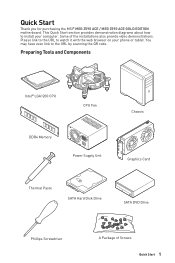
... CPU CPU Fan DDR4 Memory Power Supply Unit Chassis Graphics Card Thermal Paste SATA Hard Disk Drive SATA DVD Drive Phillips Screwdriver A Package of the installations also provide video demonstrations. Please link to the URL to watch it with the web browser on your computer. This Quick Start section provides demonstration diagrams about how to the URL by scanning the QR code. Quick Start Thank you for purchasing the MSI® MEG Z590 ACE / MEG Z590 ACE GOLD EDITION motherboard...
... CPU CPU Fan DDR4 Memory Power Supply Unit Chassis Graphics Card Thermal Paste SATA Hard Disk Drive SATA DVD Drive Phillips Screwdriver A Package of the installations also provide video demonstrations. Please link to the URL to watch it with the web browser on your computer. This Quick Start section provides demonstration diagrams about how to the URL by scanning the QR code. Quick Start Thank you for purchasing the MSI® MEG Z590 ACE / MEG Z590 ACE GOLD EDITION motherboard...
User Manual
Page 13
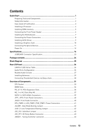
... Processor 4 Installing DDR4 memory 5 Connecting the Front Panel Header 6 Installing the Motherboard 7 Connecting the Power Connectors 8 Installing SATA Drives 9 Installing a Graphics Card 10 Connecting Peripheral Devices 11 Power On...12 Specifications...16 JCORSAIR1 Connector Specification 23 Package contents 24 Block Diagram ...25 Rear I/O Panel...26 LAN Port LED Status Table 26 Audio Ports Configuration 26 Realtek Audio Console 27 Installing Antennas 29 Connecting Thunderbolt Devices via Daisy-chain 30 Overview of Components 31 CPU Socket...33 DIMM Slots...34 PCI_E1~5: PCIe...
... Processor 4 Installing DDR4 memory 5 Connecting the Front Panel Header 6 Installing the Motherboard 7 Connecting the Power Connectors 8 Installing SATA Drives 9 Installing a Graphics Card 10 Connecting Peripheral Devices 11 Power On...12 Specifications...16 JCORSAIR1 Connector Specification 23 Package contents 24 Block Diagram ...25 Rear I/O Panel...26 LAN Port LED Status Table 26 Audio Ports Configuration 26 Realtek Audio Console 27 Installing Antennas 29 Connecting Thunderbolt Devices via Daisy-chain 30 Overview of Components 31 CPU Socket...33 DIMM Slots...34 PCI_E1~5: PCIe...
User Manual
Page 14
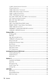
... Debug LED...54 XMP LED...54 LED_SW1: EZ LED Control 55 JPWRLED1: LED power input 55 Debug Code LED...55 Hexadecimal Character Table 56 Boot Phases...56 Debug Code LED Table 56 ACPI States Codes 60 CPU Temperature 60 Installing OS, Drivers & MSI Center 61 Installing Windows® 10 61 Installing Drivers 61 MSI Center...61 Nahimic 3...62 Installation and Update 62 Audio Tab...62 Microphone Tab...63 Sound Tracker Tab 64 Settings Tab...64 UEFI BIOS...65 BIOS Setup...66 Entering BIOS Setup 66 BIOS User Guide...
... Debug LED...54 XMP LED...54 LED_SW1: EZ LED Control 55 JPWRLED1: LED power input 55 Debug Code LED...55 Hexadecimal Character Table 56 Boot Phases...56 Debug Code LED Table 56 ACPI States Codes 60 CPU Temperature 60 Installing OS, Drivers & MSI Center 61 Installing Windows® 10 61 Installing Drivers 61 MSI Center...61 Nahimic 3...62 Installation and Update 62 Audio Tab...62 Microphone Tab...63 Sound Tracker Tab 64 Settings Tab...64 UEFI BIOS...65 BIOS Setup...66 Entering BIOS Setup 66 BIOS User Guide...
User Manual
Page 17
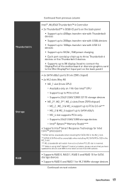
... the motherboard or discrete graphics card to the Mini DisplayPort Input port on the back panel) ∙∙6x SATA 6Gb/s ports (from Z590 chipset) ∙∙4x M.2 slots (Key M) ▪▪M2_1 slot (from CPU) ▫▫Available only on 11th Gen Intel® CPU ▫▫Supports up to PCIe 4.0 x4 ▫▫Supports 2242/ 2260/ 2280/ 22110 storage devices ▪▪M2_2*, M2_3**, M2_4 slots (from Z590 chipset) ▫...
... the motherboard or discrete graphics card to the Mini DisplayPort Input port on the back panel) ∙∙6x SATA 6Gb/s ports (from Z590 chipset) ∙∙4x M.2 slots (Key M) ▪▪M2_1 slot (from CPU) ▫▫Available only on 11th Gen Intel® CPU ▫▫Supports up to PCIe 4.0 x4 ▫▫Supports 2242/ 2260/ 2280/ 22110 storage devices ▪▪M2_2*, M2_3**, M2_4 slots (from Z590 chipset) ▫...
User Manual
Page 19
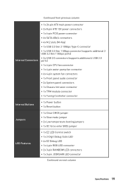
... 4-pin water-pump fan connector ∙∙6x 4-pin system fan connectors ∙∙1x Front panel audio connector ∙∙2x System panel connectors ∙∙1x Chassis Intrusion connector ∙∙1x TPM module connector ∙∙1x Tuning Controller connector Internal Buttons Jumpers LED Features ∙∙1x Power button ∙∙1x Reset button ∙∙1x Clear CMOS jumper ∙∙1x Slow mode jumper ∙∙2x Low temperature booting jumpers ∙∙1x OC force enter BIOS jumper...
... 4-pin water-pump fan connector ∙∙6x 4-pin system fan connectors ∙∙1x Front panel audio connector ∙∙2x System panel connectors ∙∙1x Chassis Intrusion connector ∙∙1x TPM module connector ∙∙1x Tuning Controller connector Internal Buttons Jumpers LED Features ∙∙1x Power button ∙∙1x Reset button ∙∙1x Clear CMOS jumper ∙∙1x Slow mode jumper ∙∙2x Low temperature booting jumpers ∙∙1x OC force enter BIOS jumper...
User Manual
Page 26
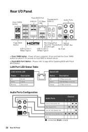
.../ Front Speaker Out Mic In (●: connected, Blank: empty) 26 Rear I /O Panel Clear CMOS button Flash BIOS Port Thunderbolt 4 USB 2.0 2.5 Gbps (USB-C) LAN Audio Ports Flash BIOS Button USB 3.2 Gen 1 5Gbps Type A Mini DisplayPort Optical Input (for Updating BIOS with Flash BIOS Button. Please refer to default values. ∙∙ Flash BIOS Port/ Button - Press and hold the Clear CMOS button for about 5-10 seconds to reset BIOS to page 68 for Thunderbolt S/PDIF-Out passthrough) USB 3.2 Gen 2 10Gbps Type A Wi-Fi 6E ∙∙ Clear CMOS button - Power off...
.../ Front Speaker Out Mic In (●: connected, Blank: empty) 26 Rear I /O Panel Clear CMOS button Flash BIOS Port Thunderbolt 4 USB 2.0 2.5 Gbps (USB-C) LAN Audio Ports Flash BIOS Button USB 3.2 Gen 1 5Gbps Type A Mini DisplayPort Optical Input (for Updating BIOS with Flash BIOS Button. Please refer to default values. ∙∙ Flash BIOS Port/ Button - Press and hold the Clear CMOS button for about 5-10 seconds to reset BIOS to page 68 for Thunderbolt S/PDIF-Out passthrough) USB 3.2 Gen 2 10Gbps Type A Wi-Fi 6E ∙∙ Clear CMOS button - Power off...
User Manual
Page 32
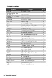
... T_SEN1 Port Type Multi-BIOS Switch Fan Connectors Power Connectors LGA1200 CPU Socket Memory slots Front Audio Connector Clear CMOS (Reset BIOS) Jumper Chassis Intrusion Connector CORSAIR Connector Tuning Controller connector Front Panel Connectors Low Temperature Booting Jumper Safe Boot Jumper OC Retry Button Connector LED power input Addressable RGB LED connectors RGB LED connector Slow Mode Booting Jumper TPM Module Connector USB 2.0 Connectors USB 3.2 Gen 1 Connector USB 3.2 Gen 2 Type-C Connector EZ LED Control M.2 Slots (Key M) PCIe Expansion Slots Power Button, Reset Button SATA 6Gb...
... T_SEN1 Port Type Multi-BIOS Switch Fan Connectors Power Connectors LGA1200 CPU Socket Memory slots Front Audio Connector Clear CMOS (Reset BIOS) Jumper Chassis Intrusion Connector CORSAIR Connector Tuning Controller connector Front Panel Connectors Low Temperature Booting Jumper Safe Boot Jumper OC Retry Button Connector LED power input Addressable RGB LED connectors RGB LED connector Slow Mode Booting Jumper TPM Module Connector USB 2.0 Connectors USB 3.2 Gen 1 Connector USB 3.2 Gen 2 Type-C Connector EZ LED Control M.2 Slots (Key M) PCIe Expansion Slots Power Button, Reset Button SATA 6Gb...

User Manual
Page 33
...) between the CPU and the heatsink to enhance heat dissipation. ∙∙Whenever the CPU is not installed, always protect the CPU socket pins by inadequate operation beyond product specifications is the Pin 1 indicator. ⚠⚠Important ∙∙Always unplug the power cord from the power outlet before booting your system. ∙∙Overheating can tolerate overclocking. Any attempt to support overclocking. MSI® does...
...) between the CPU and the heatsink to enhance heat dissipation. ∙∙Whenever the CPU is not installed, always protect the CPU socket pins by inadequate operation beyond product specifications is the Pin 1 indicator. ⚠⚠Important ∙∙Always unplug the power cord from the power outlet before booting your system. ∙∙Overheating can tolerate overclocking. Any attempt to support overclocking. MSI® does...
User Manual
Page 36
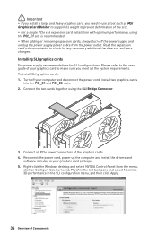
... or software changes. Turn off the power supply and unplug the power supply power cable from the menu, click on Configure SLI, Surround, PhysX in the left task pane and select Maximize 3D performance in your graphics card package. 5. Read the expansion card's documentation to check for SLI configurations, Please refer to prevent deformation of the slot. ∙∙For a single PCIe x16 expansion card installation with optimum performance, using the SLI Bridge Connector. 3. Connect...
... or software changes. Turn off the power supply and unplug the power supply power cable from the menu, click on Configure SLI, Surround, PhysX in the left task pane and select Maximize 3D performance in your graphics card package. 5. Read the expansion card's documentation to check for SLI configurations, Please refer to prevent deformation of the slot. ∙∙For a single PCIe x16 expansion card installation with optimum performance, using the SLI Bridge Connector. 3. Connect...
User Manual
Page 50
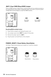
... jumper cap from a battery located on the motherboard to save system configuration data. Use a jumper cap to default values 1. POWER1, RESET1: Power Button, Reset Button The Power / Reset button allows you want to clear the system configuration, set the jumpers to power on the computer. Reset Reset button Power button 50 Overview of Components Keep Data (default) Clear CMOS/ Reset BIOS Resetting BIOS to short JBAT1 for about 5-10 seconds. 3. JBAT1: Clear CMOS (Reset BIOS) Jumper There is CMOS memory onboard that is external powered from JBAT1. 4. Plug the power cord and Power...
... jumper cap from a battery located on the motherboard to save system configuration data. Use a jumper cap to default values 1. POWER1, RESET1: Power Button, Reset Button The Power / Reset button allows you want to clear the system configuration, set the jumpers to power on the computer. Reset Reset button Power button 50 Overview of Components Keep Data (default) Clear CMOS/ Reset BIOS Resetting BIOS to short JBAT1 for about 5-10 seconds. 3. JBAT1: Clear CMOS (Reset BIOS) Jumper There is CMOS memory onboard that is external powered from JBAT1. 4. Plug the power cord and Power...
User Manual
Page 52
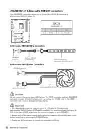
... connector and the JRAINBOW connector provide different voltages, and connecting the 5V LED strip to the JRGB connector will result in damage to the LED strip. ⚠⚠Important ∙∙The JRAINBOW connector supports up to 200 LEDs. ∙∙Always turn off the power supply and unplug the power cord from the power outlet before installing or removing the RGB LED strip. ∙∙Please use MSI's software to control...
... connector and the JRAINBOW connector provide different voltages, and connecting the 5V LED strip to the JRGB connector will result in damage to the LED strip. ⚠⚠Important ∙∙The JRAINBOW connector supports up to 200 LEDs. ∙∙Always turn off the power supply and unplug the power cord from the power outlet before installing or removing the RGB LED strip. ∙∙Please use MSI's software to control...
User Manual
Page 56
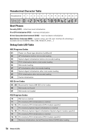
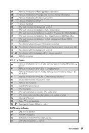
... (System Agent module specific) 19 Pre-memory PCH initialization is started 1A - 1C Pre-memory PCH initialization (PCH module specific) 2B Memory initialization. Serial Presence Detect (SPD) data reading 56 Onboard LEDs system setup, pre-OS user interface & selecting a bootable device (CD/DVD, HDD, USB, Network, Shell, ...) Debug Code LED Table SEC Progress Codes 01 Power on. memory initialization Driver Execution Environment (DXE) - Hexadecimal Character Table Hexadecimal 0 1 2 3 4 5 6 7 8 9 A B C D E F Debug Code LED display 0123456789ABCDEF Boot Phases Security (SEC...
... (System Agent module specific) 19 Pre-memory PCH initialization is started 1A - 1C Pre-memory PCH initialization (PCH module specific) 2B Memory initialization. Serial Presence Detect (SPD) data reading 56 Onboard LEDs system setup, pre-OS user interface & selecting a bootable device (CD/DVD, HDD, USB, Network, Shell, ...) Debug Code LED Table SEC Progress Codes 01 Power on. memory initialization Driver Execution Environment (DXE) - Hexadecimal Character Table Hexadecimal 0 1 2 3 4 5 6 7 8 9 A B C D E F Debug Code LED display 0123456789ABCDEF Boot Phases Security (SEC...
User Manual
Page 57
... Boot Strap Processor (BSP) selection 36 CPU post-memory initialization. Invalid memory size or memory modules do not match 53 Memory initialization error. Cache initialization 34 CPU post-memory initialization. Application Processor(s) (AP) initialization 35 CPU post-memory initialization. Configuring memory 2F Memory initialization (other) 31 Memory Installed 32 CPU post-memory initialization is started Onboard LEDs 57 Memory presence detection 2D Memory initialization. Invalid memory type or incompatible memory speed 51 Memory initialization error. 2C Memory...
... Boot Strap Processor (BSP) selection 36 CPU post-memory initialization. Invalid memory size or memory modules do not match 53 Memory initialization error. Cache initialization 34 CPU post-memory initialization. Application Processor(s) (AP) initialization 35 CPU post-memory initialization. Configuring memory 2F Memory initialization (other) 31 Memory Installed 32 CPU post-memory initialization is started Onboard LEDs 57 Memory presence detection 2D Memory initialization. Invalid memory type or incompatible memory speed 51 Memory initialization error. 2C Memory...

User Manual
Page 59
... B2 Legacy Option ROM Initialization B3 System Reset B4 USB hot plug B5 PCI bus hot plug B6 Clean-up of NVRAM B7 Configuration Reset (reset of the Architectural Protocols are found D7 No Console Input Devices are not available D4 PCI resource allocation error. E7 Reserved for Legacy Option ROM D6 No Console Output Devices are found D8 Invalid password D9 Error loading Boot Option (LoadImage returned error) DA Boot Option is failed (StartImage returned error) DB Flash update...
... B2 Legacy Option ROM Initialization B3 System Reset B4 USB hot plug B5 PCI bus hot plug B6 Clean-up of NVRAM B7 Configuration Reset (reset of the Architectural Protocols are found D7 No Console Input Devices are not available D4 PCI resource allocation error. E7 Reserved for Legacy Option ROM D6 No Console Output Devices are found D8 Invalid password D9 Error loading Boot Option (LoadImage returned error) DA Boot Option is failed (StartImage returned error) DB Flash update...
User Manual
Page 61
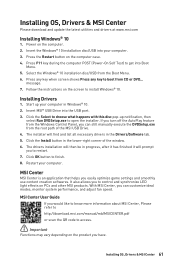
... Windows Control Panel, you can still manually execute the DVDSetup.exe from the Boot Menu. 6. With MSI Center, you can customize ideal modes, monitor system performance, and adjust fan speed. The drivers installation will find and list all necessary drivers in the lower-right corner of the MSI USB Drive. 4. Installing OS, Drivers & MSI Center 61 Select the Windows® 10 installation disc/USB from the root path of the window. 6. Insert MSI® USB Drive into the USB port...
... Windows Control Panel, you can still manually execute the DVDSetup.exe from the Boot Menu. 6. With MSI Center, you can customize ideal modes, monitor system performance, and adjust fan speed. The drivers installation will find and list all necessary drivers in the lower-right corner of the MSI USB Drive. 4. Installing OS, Drivers & MSI Center 61 Select the Windows® 10 installation disc/USB from the root path of the window. 6. Insert MSI® USB Drive into the USB port...

User Manual
Page 62
... multimedia experience (Music, Gaming, Movie or Communication). allows you 're using speakers to make them all elements of the 5 audio effects. ▪▪Surround Sound - The Quiet On / Off option allows to retrieve a multichannel listening experience over your stereo headphones or speakers. ▫▫Music - Installation and Update Nahimic 3 is included in order to enter a night mode by removing some basses.
... multimedia experience (Music, Gaming, Movie or Communication). allows you 're using speakers to make them all elements of the 5 audio effects. ▪▪Surround Sound - The Quiet On / Off option allows to retrieve a multichannel listening experience over your stereo headphones or speakers. ▫▫Music - Installation and Update Nahimic 3 is included in order to enter a night mode by removing some basses.
User Manual
Page 65
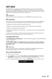
... replace with a GOP/UEFI compatible graphics card or using integrated graphics from CPU for hard drive partitions larger than 2 TB. ∙∙Supports more than 4 primary partitions with a GUID Partition Table (GPT). ∙∙Supports unlimited number of partitions ∙∙Supports full capabilities of new devices - UEFI can check the BIOS Mode at the top of the operating system to enter Boot Menu message appears on your graphics card. Power on the screen during POST...
... replace with a GOP/UEFI compatible graphics card or using integrated graphics from CPU for hard drive partitions larger than 2 TB. ∙∙Supports more than 4 primary partitions with a GUID Partition Table (GPT). ∙∙Supports unlimited number of partitions ∙∙Supports full capabilities of new devices - UEFI can check the BIOS Mode at the top of the operating system to enter Boot Menu message appears on your graphics card. Power on the screen during POST...

User Manual
Page 67
... clearing CMOS data. Updating BIOS Updating BIOS with Multi-BIOS switch. 2. And then save the BIOS file into the USB port. 3. Insert the USB flash drive that matches your motherboard model from MSI website. Switch to the target BIOS ROM with M-FLASH Before updating: Please download the latest BIOS file that contains the update file into the USB flash drive. Press to activate M-Flash for resetting BIOS. Click the M-FLASH button and click on Yes to perform the BIOS update process. 5. UEFI BIOS 67 Please refer the following methods to enter flash mode...
... clearing CMOS data. Updating BIOS Updating BIOS with Multi-BIOS switch. 2. And then save the BIOS file into the USB port. 3. Insert the USB flash drive that matches your motherboard model from MSI website. Switch to the target BIOS ROM with M-FLASH Before updating: Please download the latest BIOS file that contains the update file into the USB flash drive. Press to activate M-Flash for resetting BIOS. Click the M-FLASH button and click on Yes to perform the BIOS update process. 5. UEFI BIOS 67 Please refer the following methods to enter flash mode...
User Manual
Page 71
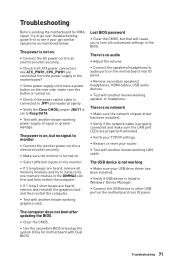
... sure the network chipset driver has been installed. ∙∙Verify if the network cable is turned on. ∙∙Select different inputs on the motherboard rear IO panel. ∙∙Remove secondary speakers/ headphones, HDMI cables, USB audio devices. ∙∙Test with another known working LAN cable. There is listed in the DIMMA2 slot first and then restart the computer. ∙∙If 1 long 2 short beeps are heard, remove and reinstall the graphics card and...
... sure the network chipset driver has been installed. ∙∙Verify if the network cable is turned on. ∙∙Select different inputs on the motherboard rear IO panel. ∙∙Remove secondary speakers/ headphones, HDMI cables, USB audio devices. ∙∙Test with another known working LAN cable. There is listed in the DIMMA2 slot first and then restart the computer. ∙∙If 1 long 2 short beeps are heard, remove and reinstall the graphics card and...
User Manual
Page 75
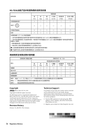
...Version 1.0, 2021/01, First release. Alternatively, please try the following help resources for technical guide, BIOS updates, driver updates, and other marks and names mentioned may be obtained from the user guide, please contact your product at: http://register.msi.com iv Regulatory Notices "超出0.1 wt 0.01 wt 2 3 PBDE Copyright Micro-Star Int'l Co.,Ltd. yy Visit the MSI...9675; ○ ○ 備考1. The MSI logo used is expressed or implied. MSI reserves the right to make changes to accuracy or completeness is a registered trademark of ...
...Version 1.0, 2021/01, First release. Alternatively, please try the following help resources for technical guide, BIOS updates, driver updates, and other marks and names mentioned may be obtained from the user guide, please contact your product at: http://register.msi.com iv Regulatory Notices "超出0.1 wt 0.01 wt 2 3 PBDE Copyright Micro-Star Int'l Co.,Ltd. yy Visit the MSI...9675; ○ ○ 備考1. The MSI logo used is expressed or implied. MSI reserves the right to make changes to accuracy or completeness is a registered trademark of ...


