User Manual
Page 1
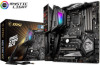
Quick Start Thank you for purchasing the MSI® MEG Z390 ACE motherboard. Some of Screws Quick Start 1 You may have even link to watch it with the web browser on your computer. This Quick Start section provides ...
Quick Start Thank you for purchasing the MSI® MEG Z390 ACE motherboard. Some of Screws Quick Start 1 You may have even link to watch it with the web browser on your computer. This Quick Start section provides ...
User Manual
Page 5
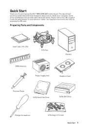
Installing the Motherboard 1 2 Quick Start 5 BAT1
Installing the Motherboard 1 2 Quick Start 5 BAT1
User Manual
Page 11
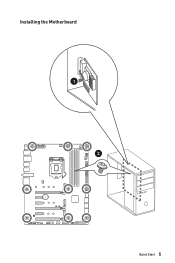
Contents Quick Start ...1 Preparing Tools and Components 1 Installing a Processor 2 Installing DDR4 memory 3 Connecting the Front Panel Header 4 Installing the Motherboard 5 Installing SATA Drives 6 Installing a Graphics Card 7 Connecting Peripheral Devices 8 Connecting the Power Connectors 9 Power On...10 Specifications...14 JCORSAIR1 Connector Specification 19 Package contents 20 ...
Contents Quick Start ...1 Preparing Tools and Components 1 Installing a Processor 2 Installing DDR4 memory 3 Connecting the Front Panel Header 4 Installing the Motherboard 5 Installing SATA Drives 6 Installing a Graphics Card 7 Connecting Peripheral Devices 8 Connecting the Power Connectors 9 Power On...10 Specifications...14 JCORSAIR1 Connector Specification 19 Package contents 20 ...
User Manual
Page 20
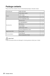
It should contain: Motherboard MEG Z390 ACE SATA 6Gb/s Cables 4 LED Y Cable 1 Cable LED JCORSAIR Cable 1 LED JRAINBOW Cable 1 Antenna Set 1 SLI HB BRIDGE M 1 M.2 Screw 3 Accessories Case Badge 1 SATA Cable Lables 1 Product Registration Card 1 Application DVD Driver DVD 1 User Manual 1 Documentation Quick Installation Guide 1 Important If any of your retailer. 20 Package contents Package contents Please check the contents of the above items are damaged or missing, please contact your motherboard package.
It should contain: Motherboard MEG Z390 ACE SATA 6Gb/s Cables 4 LED Y Cable 1 Cable LED JCORSAIR Cable 1 LED JRAINBOW Cable 1 Antenna Set 1 SLI HB BRIDGE M 1 M.2 Screw 3 Accessories Case Badge 1 SATA Cable Lables 1 Product Registration Card 1 Application DVD Driver DVD 1 User Manual 1 Documentation Quick Installation Guide 1 Important If any of your retailer. 20 Package contents Package contents Please check the contents of the above items are damaged or missing, please contact your motherboard package.
User Manual
Page 28
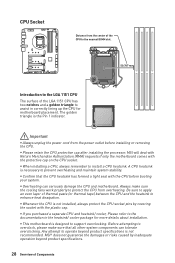
... pins by inadequate operation beyond product specifications is the Pin 1 indicator. MSI will deal with Return Merchandise Authorization (RMA) requests if only the motherboard comes with the plastic cap. y This motherboard is necessary to enhance heat dissipation. y Confirm that all other system components... can seriously damage the CPU and motherboard. Before attempting to overclock, please make sure the cooling fans work properly to install a CPU heatsink. MSI® does not guarantee the damages or risks caused by covering the...
... pins by inadequate operation beyond product specifications is the Pin 1 indicator. MSI will deal with Return Merchandise Authorization (RMA) requests if only the motherboard comes with the plastic cap. y This motherboard is necessary to enhance heat dissipation. y Confirm that all other system components... can seriously damage the CPU and motherboard. Before attempting to overclock, please make sure the cooling fans work properly to install a CPU heatsink. MSI® does not guarantee the damages or risks caused by covering the...
User Manual
Page 29
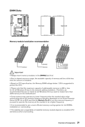
... amount of Components 29 y Based on its Serial Presence Detect (SPD). Therefore, we recommended that the maximum capacity of installed memory module depend on the motherboard. y The stability and compatibility of addressable memory is recommended to chipset resource usage, the available capacity of memory will be a little less than 4GB memory...
... amount of Components 29 y Based on its Serial Presence Detect (SPD). Therefore, we recommended that the maximum capacity of installed memory module depend on the motherboard. y The stability and compatibility of addressable memory is recommended to chipset resource usage, the available capacity of memory will be a little less than 4GB memory...
User Manual
Page 32
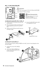
...~3: M.2 Slots (Key M) Important y Intel® RST only supports PCIe M.2 SSD with the supplied M.2 screw. 3 4 2 30° Supplied M.2 screw 1 Installing M.2 module (M2_3) This motherboard has M.2 SHIELD FROZR on the M2_3 slot for your M.2 SSD into the M.2 slot at a 30-degree angle. 4. Lift the M.2 SHIELD FROZR and remove the protecting... screw from the M.2 module. 1. M2_1 Video Demonstration M2_2 Watch the video to learn how to the appropriate position for heat dissipation from the motherboard. 2. Move and fasten the M.2 mounting screw to M2_3 Install M.2 module.
...~3: M.2 Slots (Key M) Important y Intel® RST only supports PCIe M.2 SSD with the supplied M.2 screw. 3 4 2 30° Supplied M.2 screw 1 Installing M.2 module (M2_3) This motherboard has M.2 SHIELD FROZR on the M2_3 slot for your M.2 SSD into the M.2 slot at a 30-degree angle. 4. Lift the M.2 SHIELD FROZR and remove the protecting... screw from the M.2 module. 1. M2_1 Video Demonstration M2_2 Watch the video to learn how to the appropriate position for heat dissipation from the motherboard. 2. Move and fasten the M.2 mounting screw to M2_3 Install M.2 module.
User Manual
Page 34
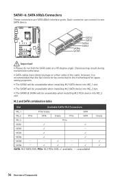
... be unavailable when installing M.2 PCIe device into M2_2 slot. y SATA cables have identical plugs on either sides of Components Each connector can connect to the motherboard for space saving purposes. M.2 and SATA combination table Slot Available SATA/ M.2 Connectors M2_1 PCIe/ Empty SATA M2_2 PCIe SATA Empty PCIe SATA M2_3 PCIe SATA1...
... be unavailable when installing M.2 PCIe device into M2_2 slot. y SATA cables have identical plugs on either sides of Components Each connector can connect to the motherboard for space saving purposes. M.2 and SATA combination table Slot Available SATA/ M.2 Connectors M2_1 PCIe/ Empty SATA M2_2 PCIe SATA Empty PCIe SATA M2_3 PCIe SATA1...
User Manual
Page 36
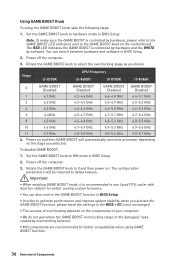
... you activate the GAME BOOST function, please leave the settings in BIOS Setup. 2. The configuration parameters will automatically overclock processor depending on the motherboard. Power off the computer. 3. y You can switch between hardware and software in the BIOS > OC menu unchanged. y The success of... Components The RED LED indicates the GAME BOOST is controlled by hardware and the WHITE by overclocking behavior. y MSI components are recommended for better cooling and performance. Set the GAME BOOST knob to select the overclocking stage as you desire.
... you activate the GAME BOOST function, please leave the settings in BIOS Setup. 2. The configuration parameters will automatically overclock processor depending on the motherboard. Power off the computer. 3. y You can switch between hardware and software in the BIOS > OC menu unchanged. y The success of... Components The RED LED indicates the GAME BOOST is controlled by hardware and the WHITE by overclocking behavior. y MSI components are recommended for better cooling and performance. Set the GAME BOOST knob to select the overclocking stage as you desire.
User Manual
Page 38
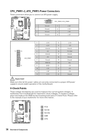
... +5V +5V +5V Ground Important Make sure that all the power cables are used to check voltages. Please refer to ensure stable operation of the motherboard. A multimeter (not included) will be required to measure the current system voltages. PCH VCCIO VCCSA DDR CPU 38 Overview of your multimeter for more information...
... +5V +5V +5V Ground Important Make sure that all the power cables are used to check voltages. Please refer to ensure stable operation of the motherboard. A multimeter (not included) will be required to measure the current system voltages. PCH VCCIO VCCSA DDR CPU 38 Overview of your multimeter for more information...
User Manual
Page 39
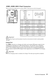
... will need to install the MSI Dragon Center application to turn ON/OFF the charging mode. Overview of Components 39 JUSB1, JUSB3: USB 3.1 Gen1 Connectors These connectors allow you will be connected correctly to avoid possible damage. Charger Port The JUSB3 connector is hardware controlled by motherboard chip, it can increase USB...
... will need to install the MSI Dragon Center application to turn ON/OFF the charging mode. Overview of Components 39 JUSB1, JUSB3: USB 3.1 Gen1 Connectors These connectors allow you will be connected correctly to avoid possible damage. Charger Port The JUSB3 connector is hardware controlled by motherboard chip, it can increase USB...

User Manual
Page 43
... located on / off the computer and unplug the power cord. 2. POWER1, RESET1: Power Button, Reset Button The Power button allows you to power on the motherboard to save system configuration data. Reset Power button Reset button JBAT1: Clear CMOS (Reset BIOS) Jumper There is CMOS memory onboard that is external powered...
... located on / off the computer and unplug the power cord. 2. POWER1, RESET1: Power Button, Reset Button The Power button allows you to power on the motherboard to save system configuration data. Reset Power button Reset button JBAT1: Clear CMOS (Reset BIOS) Jumper There is CMOS memory onboard that is external powered...
User Manual
Page 45
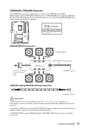
... to connect the CORSAIR Individually Addressable Lighting PRO RGB LED strips 5V or CORSAIR RGB fans with MSI's software. 1 JCORSAIR1 1 +5V 2 3 Ground Data CORSAIR RGB Fan Connection Connect the SATA Power connector to the motherboard specification. Overview of RGB Fans or Lighting PRO RGB LED strips supported may differ between models. Please...
... to connect the CORSAIR Individually Addressable Lighting PRO RGB LED strips 5V or CORSAIR RGB fans with MSI's software. 1 JCORSAIR1 1 +5V 2 3 Ground Data CORSAIR RGB Fan Connection Connect the SATA Power connector to the motherboard specification. Overview of RGB Fans or Lighting PRO RGB LED strips supported may differ between models. Please...

User Manual
Page 46
... GPU is enabled. indicates the booting device is not detected or fail. Onboard LEDs EZ Debug LED These LEDs indicate the debug status of the motherboard. indicates CPU is not detected or fail. BOOT -
... GPU is enabled. indicates the booting device is not detected or fail. Onboard LEDs EZ Debug LED These LEDs indicate the debug status of the motherboard. indicates CPU is not detected or fail. BOOT -
User Manual
Page 57
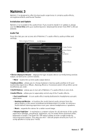
.... ƒ Surround Sound - The Quiet On / Off option allows to offer the best audio experience it in order to retrieve a multichannel listening experience over your motherboard or download the driver from the game engine or the movie soundtrack and downmixes it contains audio effects, microphone effects and Sound Tracker. Nahimic 3 Nahimic... volume for a wider sound stage. ƒ Volume Stabilizer - displays the type of Nahimic 3's audio effects in the audio driver. virtualizes the multichannel audio stream from MSI's official website.
.... ƒ Surround Sound - The Quiet On / Off option allows to offer the best audio experience it in order to retrieve a multichannel listening experience over your motherboard or download the driver from the game engine or the movie soundtrack and downmixes it contains audio effects, microphone effects and Sound Tracker. Nahimic 3 Nahimic... volume for a wider sound stage. ƒ Volume Stabilizer - displays the type of Nahimic 3's audio effects in the audio driver. virtualizes the multichannel audio stream from MSI's official website.
User Manual
Page 61
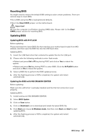
...Be sure the computer is set properly. Updating BIOS: 1. Insert the USB flash drive that matches your motherboard model from MSI website. Updating BIOS Updating BIOS with MSI DRAGON CENTER Before updating: Make sure the LAN driver is already installed and the Internet connection is off ...before clearing CMOS data. Click the M-FLASH button and click on the motherboard. And then save the BIOS file into the ...
...Be sure the computer is set properly. Updating BIOS: 1. Insert the USB flash drive that matches your motherboard model from MSI website. Updating BIOS Updating BIOS with MSI DRAGON CENTER Before updating: Make sure the LAN driver is already installed and the Internet connection is off ...before clearing CMOS data. Click the M-FLASH button and click on the motherboard. And then save the BIOS file into the ...
User Manual
Page 62
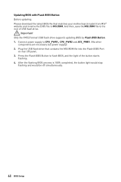
... FAT32 format USB flash drive supports updating BIOS by Flash BIOS Button. 1. Press the Flash BIOS Button to MSI.ROM. Plug the USB flash drive that matches your motherboard model from MSI® website and rename the BIOS file to flash BIOS, and the light of USB flash drive. After ... BIOS Setup Updating BIOS with Flash BIOS Button Before updating: Please download the latest BIOS file that contains the MSI.ROM file into the Flash BIOS Port on rear I/O panel. 3. And then, save the MSI.ROM file to CPU_PWR1,CPU_PWR2 and ATX_PWR1. (No other components are necessary but power supply.) 2.
... FAT32 format USB flash drive supports updating BIOS by Flash BIOS Button. 1. Press the Flash BIOS Button to MSI.ROM. Plug the USB flash drive that matches your motherboard model from MSI® website and rename the BIOS file to flash BIOS, and the light of USB flash drive. After ... BIOS Setup Updating BIOS with Flash BIOS Button Before updating: Please download the latest BIOS file that contains the MSI.ROM file into the Flash BIOS Port on rear I/O panel. 3. And then, save the MSI.ROM file to CPU_PWR1,CPU_PWR2 and ATX_PWR1. (No other components are necessary but power supply.) 2.
User Manual
Page 65
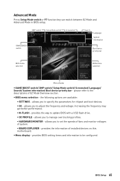
... chipset and boot devices. ƒ OC - allows you to manage overclocking profiles. ƒ HARDWARE MONITOR - allows you to the descriptions of installed devices on this motherboard.
... chipset and boot devices. ƒ OC - allows you to manage overclocking profiles. ƒ HARDWARE MONITOR - allows you to the descriptions of installed devices on this motherboard.

User Manual
Page 66
The year can be adjusted by BIOS. f SATA PortX/ M2_X Shows the information of the device and motherboard. f System Information Shows detailed system information, including CPU type, BIOS version, and Memory (read only). Press Enter to Sat, determined by users. Day of the ...
The year can be adjusted by BIOS. f SATA PortX/ M2_X Shows the information of the device and motherboard. f System Information Shows detailed system information, including CPU type, BIOS version, and Memory (read only). Press Enter to Sat, determined by users. Day of the ...
User Manual
Page 74
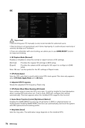
.... This item appears when the installed CPU supports this setting automatically. The valid value range depends on motherboard. Enabling GAME BOOST function can automatically overclock the system with overclocking, we advise you are unfamiliar with MSI optimized overclocking profile. f Adjusted CPU Frequency Shows the adjusted CPU frequency. f Game Boost Function Control [By...
.... This item appears when the installed CPU supports this setting automatically. The valid value range depends on motherboard. Enabling GAME BOOST function can automatically overclock the system with overclocking, we advise you are unfamiliar with MSI optimized overclocking profile. f Adjusted CPU Frequency Shows the adjusted CPU frequency. f Game Boost Function Control [By...


