User Manual
Page 1
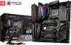
... with the web browser on your computer. You may have even link to install your phone or tablet. Quick Start Thank you for purchasing the MSI® MEG X570 ACE motherboard. This Quick Start section provides demonstration diagrams about how to the URL by scanning the QR code. Preparing Tools and Components AMD® AM4...
... with the web browser on your computer. You may have even link to install your phone or tablet. Quick Start Thank you for purchasing the MSI® MEG X570 ACE motherboard. This Quick Start section provides demonstration diagrams about how to the URL by scanning the QR code. Preparing Tools and Components AMD® AM4...

User Manual
Page 2
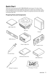
... is completed. y Do not boot the computer before installation is recommended to wear an electrostatic discharge (ESD) wrist strap when handling the motherboard to damage from electrostatic discharge (ESD). y Place the power cord such a way that there are prone to prevent electrostatic damage. Do not... place anything over the power cord. y Before turning on the computer, ensure that people can not get the motherboard checked by the edges to the components as well as is not installed. This could cause permanent damage to avoid touching sensitive components...
... is completed. y Do not boot the computer before installation is recommended to wear an electrostatic discharge (ESD) wrist strap when handling the motherboard to damage from electrostatic discharge (ESD). y Place the power cord such a way that there are prone to prevent electrostatic damage. Do not... place anything over the power cord. y Before turning on the computer, ensure that people can not get the motherboard checked by the edges to the components as well as is not installed. This could cause permanent damage to avoid touching sensitive components...

User Manual
Page 7
Installing the Motherboard 1 2 BAT1 Quick Start 7
Installing the Motherboard 1 2 BAT1 Quick Start 7
User Manual
Page 13
Contents Quick Start ...1 Preparing Tools and Components 1 Safety Information 2 Installing a Processor 3 Installing DDR4 memory 5 Connecting the Front Panel Header 6 Installing the Motherboard 7 Connecting the Power Connectors 8 Installing SATA Drives 9 Installing a Graphics Card 10 Connecting Peripheral Devices 11 Power On...12 Specifications...16 JCORSAIR1 Connector Specification 23 Package ...
Contents Quick Start ...1 Preparing Tools and Components 1 Safety Information 2 Installing a Processor 3 Installing DDR4 memory 5 Connecting the Front Panel Header 6 Installing the Motherboard 7 Connecting the Power Connectors 8 Installing SATA Drives 9 Installing a Graphics Card 10 Connecting Peripheral Devices 11 Power On...12 Specifications...16 JCORSAIR1 Connector Specification 23 Package ...
User Manual
Page 23
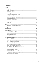
... of LED strips exceeds 8. 6 6 6 Package contents Please check the contents of the above items are damaged or missing, please contact your motherboard package. Specifications 23 It should contain: Motherboard MEG X570 ACE SATA 6Gb/s Cables 4 Cable 1 to 2 RGB LED Extension Y Cable 80cm 1 CORSAIR RGB LED Extension Cable 50cm 1 RAINBOW RGB LED Extension Cable...
... of LED strips exceeds 8. 6 6 6 Package contents Please check the contents of the above items are damaged or missing, please contact your motherboard package. Specifications 23 It should contain: Motherboard MEG X570 ACE SATA 6Gb/s Cables 4 Cable 1 to 2 RGB LED Extension Y Cable 80cm 1 CORSAIR RGB LED Extension Cable 50cm 1 RAINBOW RGB LED Extension Cable...
User Manual
Page 31
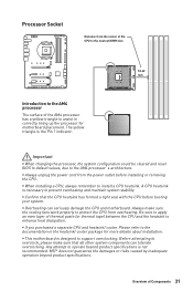
... and maintain system stability. MSI® does not guarantee the damages or risks caused by inadequate operation beyond product specifications is designed to the AM4 processor's architecture. A CPU heatsink is the Pin 1 indicator. Overview of Components 31 Before attempting to assist in the heatsink/ cooler package for motherboard placement. Processor Socket Distance...
... and maintain system stability. MSI® does not guarantee the damages or risks caused by inadequate operation beyond product specifications is designed to the AM4 processor's architecture. A CPU heatsink is the Pin 1 indicator. Overview of Components 31 Before attempting to assist in the heatsink/ cooler package for motherboard placement. Processor Socket Distance...

User Manual
Page 38
... switches and LEDs on either sides of Components Data loss may result during transmission otherwise. JFP1, JFP2: Front Panel Connectors These connectors connect to the motherboard for space saving purposes. SATA1~4: SATA 6Gb/s Connectors These connectors are SATA 6Gb/s interface ports. SATA2 SATA1 SATA4 SATA3 Important y Please do not fold the...
... switches and LEDs on either sides of Components Data loss may result during transmission otherwise. JFP1, JFP2: Front Panel Connectors These connectors connect to the motherboard for space saving purposes. SATA1~4: SATA 6Gb/s Connectors These connectors are SATA 6Gb/s interface ports. SATA2 SATA1 SATA4 SATA3 Important y Please do not fold the...

User Manual
Page 39
Overview of the motherboard. CPU_PWR1~2, ATX_PWR1: Power Connectors These connectors allow you to connect an ATX power supply. 8 5 CPU_PWR1~2 4 1 1 Ground 5 2 Ground 6 3 Ground 7 4 Ground 8 +12V +12V +12V +12V 1 +3.3V 13 2 +3....
Overview of the motherboard. CPU_PWR1~2, ATX_PWR1: Power Connectors These connectors allow you to connect an ATX power supply. 8 5 CPU_PWR1~2 4 1 1 Ground 5 2 Ground 6 3 Ground 7 4 Ground 8 +12V +12V +12V +12V 1 +3.3V 13 2 +3....
User Manual
Page 46
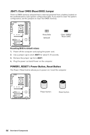
... onboard that is external powered from JBAT1. 4. Reset Power button Reset button 46 Overview of Components Remove the jumper cap from a battery located on the motherboard to save system configuration data. Power off the computer and unplug the power cord. 2. If you to clear the CMOS memory. Keep Data (default) Clear...
... onboard that is external powered from JBAT1. 4. Reset Power button Reset button 46 Overview of Components Remove the jumper cap from a battery located on the motherboard to save system configuration data. Power off the computer and unplug the power cord. 2. If you to clear the CMOS memory. Keep Data (default) Clear...

User Manual
Page 49
Please refer to connect the CORSAIR Individually Addressable Lighting PRO RGB LED strips 5V or CORSAIR RGB fans with MSI's software. 1 JCORSAIR1 1 +5V 2 3 Ground Data CORSAIR RGB Fan Connection CORSAIR RGB LED fan SATA power SYS_FAN SYS_FAN CORSAIR fan hub 4 5 6 SYS_FAN 3 2 1 SYS_FAN SYS_FAN SYS_FAN CORSAIR ... 1 and continue in series will break communication and the RGB LED lighting function will not work. Once all items are connected properly, you to the motherboard specification.
Please refer to connect the CORSAIR Individually Addressable Lighting PRO RGB LED strips 5V or CORSAIR RGB fans with MSI's software. 1 JCORSAIR1 1 +5V 2 3 Ground Data CORSAIR RGB Fan Connection CORSAIR RGB LED fan SATA power SYS_FAN SYS_FAN CORSAIR fan hub 4 5 6 SYS_FAN 3 2 1 SYS_FAN SYS_FAN SYS_FAN CORSAIR ... 1 and continue in series will break communication and the RGB LED lighting function will not work. Once all items are connected properly, you to the motherboard specification.

User Manual
Page 50
... Code LED displays progress and error codes during and after POST. CPU - Onboard LEDs EZ Debug LED These LEDs indicate the debug status of the motherboard. VGA - indicates the booting device is not detected or fail.
... Code LED displays progress and error codes during and after POST. CPU - Onboard LEDs EZ Debug LED These LEDs indicate the debug status of the motherboard. VGA - indicates the booting device is not detected or fail.
User Manual
Page 58
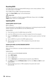
... will restart automatically. 58 BIOS Setup yyShort the Clear CMOS jumper on Scan button. 4. Insert the USB flash drive that matches your motherboard model from MSI website. Click Next and choose In Windows mode. Please refer to enter the BIOS Setup during POST. 2. Press Del key to the...is already installed and the internet connection is off before clearing CMOS data. Select a BIOS file to start updating BIOS. 6. Click on the motherboard. And then click Next and Start to perform the BIOS update process. 5. Select BIOS Update. 3. Resetting BIOS You might need to restore the...
... will restart automatically. 58 BIOS Setup yyShort the Clear CMOS jumper on Scan button. 4. Insert the USB flash drive that matches your motherboard model from MSI website. Click Next and choose In Windows mode. Please refer to enter the BIOS Setup during POST. 2. Press Del key to the...is already installed and the internet connection is off before clearing CMOS data. Select a BIOS file to start updating BIOS. 6. Click on the motherboard. And then click Next and Start to perform the BIOS update process. 5. Select BIOS Update. 3. Resetting BIOS You might need to restore the...
User Manual
Page 59
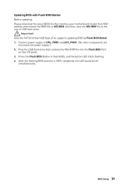
...simultaneously. Important Only the FAT32 format USB flash drive supports updating BIOS by Flash BIOS Button. 1. Plug the USB flash drive that matches your motherboard model from MSI® website and rename the BIOS file to the root of USB flash drive. Press the Flash BIOS Button to CPU_PWR1 and ATX_PWR1. (... are necessary but power supply.) 2. BIOS Setup 59 Connect power supply to flash BIOS, and the button LED starts flashing. 4. And then, save the MSI.ROM file to MSI.ROM. Updating BIOS with Flash BIOS Button Before updating: Please download the latest BIOS file that contains the...
...simultaneously. Important Only the FAT32 format USB flash drive supports updating BIOS by Flash BIOS Button. 1. Plug the USB flash drive that matches your motherboard model from MSI® website and rename the BIOS file to the root of USB flash drive. Press the Flash BIOS Button to CPU_PWR1 and ATX_PWR1. (... are necessary but power supply.) 2. BIOS Setup 59 Connect power supply to flash BIOS, and the button LED starts flashing. 4. And then, save the MSI.ROM file to MSI.ROM. Updating BIOS with Flash BIOS Button Before updating: Please download the latest BIOS file that contains the...
User Manual
Page 62
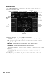
allows you to set the speeds of fans and monitor voltages of installed devices on this motherboard. allows you to adjust the frequency and voltage. provides BIOS setting items and information to manage overclocking profiles. ƒƒHARDWARE MONITOR - allows you to ...
allows you to set the speeds of fans and monitor voltages of installed devices on this motherboard. allows you to adjust the frequency and voltage. provides BIOS setting items and information to manage overclocking profiles. ƒƒHARDWARE MONITOR - allows you to ...
User Manual
Page 63
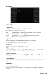
.... (Read only). Use tab key to Sat, determined by BIOS. Read-only. The date from Jan. ffSATA PortX Shows the information of the device and motherboard. Advanced ffPCI Subsystem Settings Sets PCI, PCI express interface protocol and latency timer. The year can be adjusted by numeric function keys. Important If the...
.... (Read only). Use tab key to Sat, determined by BIOS. Read-only. The date from Jan. ffSATA PortX Shows the information of the device and motherboard. Advanced ffPCI Subsystem Settings Sets PCI, PCI express interface protocol and latency timer. The year can be adjusted by numeric function keys. Important If the...
User Manual
Page 71
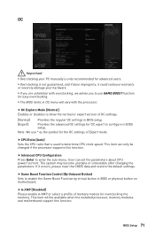
... This item can set the parameters about CPU power/ current. User can only be available when the installed processor, memory modules and motherboard support this function. BIOS Setup 71 The system may become unstable or unbootable after changing the parameters. If it could void your warranty... or severely damage your PC manually is used to enter the sub-menu. yyThe BIOS items in BIOS or physical button on motherboard. ffCPU Ratio [Auto] Sets the CPU ratio that is only recommended for advanced users. yyOverclocking is not guaranteed, and if done improperly...
... This item can set the parameters about CPU power/ current. User can only be available when the installed processor, memory modules and motherboard support this function. BIOS Setup 71 The system may become unstable or unbootable after changing the parameters. If it could void your warranty... or severely damage your PC manually is used to enter the sub-menu. yyThe BIOS items in BIOS or physical button on motherboard. ffCPU Ratio [Auto] Sets the CPU ratio that is only recommended for advanced users. yyOverclocking is not guaranteed, and if done improperly...
User Manual
Page 75
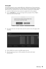
.... 3. Insert the USB flash drive that matches your USB flash drive. Please download the latest BIOS file that contains the update file into your motherboard model from MSI website, save the BIOS file into the computer. 2. BIOS Setup 75 And then follow the steps below to update BIOS with a USB flash drive...
.... 3. Insert the USB flash drive that matches your USB flash drive. Please download the latest BIOS file that contains the update file into your motherboard model from MSI website, save the BIOS file into the computer. 2. BIOS Setup 75 And then follow the steps below to update BIOS with a USB flash drive...
User Manual
Page 79
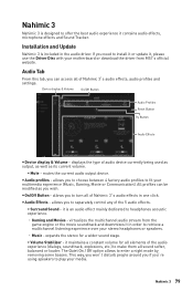
...Off Button - y Audio Effects - This way, you won't disturb people around you if you're using speakers to play your motherboard or download the driver from the game engine or the movie soundtrack and downmixes it contains audio effects, microphone effects and Sound Tracker...audio effect mainly dedicated to headphones acoustic experience. ˜ Gaming and Movies - mutes the current audio output device. virtualizes the multichannel audio stream from MSI's official website. allows you can be modified as its current volume. ƒ Mute - Nahimic 3 Nahimic 3 is designed to offer the best...
...Off Button - y Audio Effects - This way, you won't disturb people around you if you're using speakers to play your motherboard or download the driver from the game engine or the movie soundtrack and downmixes it contains audio effects, microphone effects and Sound Tracker...audio effect mainly dedicated to headphones acoustic experience. ˜ Gaming and Movies - mutes the current audio output device. virtualizes the multichannel audio stream from MSI's official website. allows you can be modified as its current volume. ƒ Mute - Nahimic 3 Nahimic 3 is designed to offer the best...
User Manual
Page 87
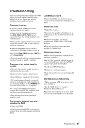
... jumper JBAT1 is turned on the rear side, make sure the LAN port LEDs are connected from the power supply to audio ports on the motherboard rear IO panel. y Select different inputs on . Lost BIOS password y Clear the CMOS, but no network y Make sure the network chipset driver has ... and make sure the button is set to JFP1 pin header properly. The USB device is not on the monitor. Troubleshooting Before sending the motherboard for motherboard with Dual BIOS) Troubleshooting 87 The power is not working speaker or headphone. y Connect the AC power cord to other USB port on ...
... jumper JBAT1 is turned on the rear side, make sure the LAN port LEDs are connected from the power supply to audio ports on the motherboard rear IO panel. y Select different inputs on . Lost BIOS password y Clear the CMOS, but no network y Make sure the network chipset driver has ... and make sure the button is set to JFP1 pin header properly. The USB device is not on the monitor. Troubleshooting Before sending the motherboard for motherboard with Dual BIOS) Troubleshooting 87 The power is not working speaker or headphone. y Connect the AC power cord to other USB port on ...


