User Manual
Page 1
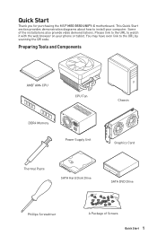
Quick Start Thank you for purchasing the MSI® MEG B550 UNIFY-X motherboard. Please link to the URL to install your phone or tablet. Preparing Tools and Components AMD® AM4 CPU CPU Fan DDR4 Memory Power Supply ...
Quick Start Thank you for purchasing the MSI® MEG B550 UNIFY-X motherboard. Please link to the URL to install your phone or tablet. Preparing Tools and Components AMD® AM4 CPU CPU Fan DDR4 Memory Power Supply ...
User Manual
Page 2
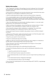
...package are securely connected. Loose connections may cause the computer to not recognize a component or fail to start. ∙∙Hold the motherboard by the edges to avoid touching sensitive components. ∙∙It is recommended to wear an electrostatic discharge (ESD) wrist strap when handling ...before installation is not installed. ∙∙Before turning on the computer, ensure that there are no loose screws or metal components on the motherboard or anywhere within the computer case. ∙∙Do not boot the computer before connecting the PSU to the user. ∙∙If...
...package are securely connected. Loose connections may cause the computer to not recognize a component or fail to start. ∙∙Hold the motherboard by the edges to avoid touching sensitive components. ∙∙It is recommended to wear an electrostatic discharge (ESD) wrist strap when handling ...before installation is not installed. ∙∙Before turning on the computer, ensure that there are no loose screws or metal components on the motherboard or anywhere within the computer case. ∙∙Do not boot the computer before connecting the PSU to the user. ∙∙If...
User Manual
Page 7
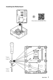
Installing the Motherboard ⚽ ⚽ https://youtu.be/wWI6Qt51Wnc 1 Torque: 3 kgf·cm* 2 *3 kgf·cm = 0.3 N·m = 2.6 lbf·in BAT1 Quick Start 7
Installing the Motherboard ⚽ ⚽ https://youtu.be/wWI6Qt51Wnc 1 Torque: 3 kgf·cm* 2 *3 kgf·cm = 0.3 N·m = 2.6 lbf·in BAT1 Quick Start 7
User Manual
Page 13
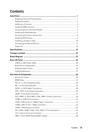
Contents Quick Start...1 Preparing Tools and Components 1 Safety Information 2 Installing a Processor 3 Installing DDR4 memory 5 Connecting the Front Panel Header 6 Installing the Motherboard 7 Connecting the Power Connectors 8 Installing SATA Drives 9 Installing a Graphics Card 10 Connecting Peripheral Devices 11 Power On...12 Specifications...15 Package contents 22 Block Diagram ......
Contents Quick Start...1 Preparing Tools and Components 1 Safety Information 2 Installing a Processor 3 Installing DDR4 memory 5 Connecting the Front Panel Header 6 Installing the Motherboard 7 Connecting the Power Connectors 8 Installing SATA Drives 9 Installing a Graphics Card 10 Connecting Peripheral Devices 11 Power On...12 Specifications...15 Package contents 22 Block Diagram ......
User Manual
Page 22
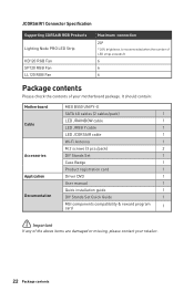
...It should contain: Motherboard Cable Accessories Application Documentation MEG B550 UNIFY-X SATA 6G cables (2 cables/pack) 1 LED JRAINBOW cable 1 LED JRGB Y cable 1 LED JCORSAIR cable 1 Wi-Fi Antenna 1 M.2 screws (3 pcs./pack) 2 DIY Stands Set 1 Case Badge 1 Product registration card 1 Driver DVD 1 User manual 1 Quick installation guide 1 DIY Stands Set Quick Guide 1 MSI components compatibility &... number of LED strips exceeds 8. 6 6 6 Package contents Please check the contents of the above items are damaged or missing, please contact your motherboard package.
...It should contain: Motherboard Cable Accessories Application Documentation MEG B550 UNIFY-X SATA 6G cables (2 cables/pack) 1 LED JRAINBOW cable 1 LED JRGB Y cable 1 LED JCORSAIR cable 1 Wi-Fi Antenna 1 M.2 screws (3 pcs./pack) 2 DIY Stands Set 1 Case Badge 1 Product registration card 1 Driver DVD 1 User manual 1 Quick installation guide 1 DIY Stands Set Quick Guide 1 MSI components compatibility &... number of LED strips exceeds 8. 6 6 6 Package contents Please check the contents of the above items are damaged or missing, please contact your motherboard package.
User Manual
Page 30
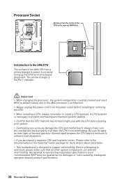
...to prevent overheating and maintain system stability. ∙∙Confirm that all other system components can seriously damage the CPU and motherboard. Before attempting to overclock, please make sure the cooling fans work properly to protect the CPU from the center of the ... booting your system. ∙∙Overheating can tolerate overclocking. Processor Socket Distance from overheating. The yellow triangle is not recommended. MSI® does not guarantee the damages or risks caused by inadequate operation beyond product specifications is the Pin 1 indicator. ⚠&#...
...to prevent overheating and maintain system stability. ∙∙Confirm that all other system components can seriously damage the CPU and motherboard. Before attempting to overclock, please make sure the cooling fans work properly to protect the CPU from the center of the ... booting your system. ∙∙Overheating can tolerate overclocking. Processor Socket Distance from overheating. The yellow triangle is not recommended. MSI® does not guarantee the damages or risks caused by inadequate operation beyond product specifications is the Pin 1 indicator. ⚠&#...
User Manual
Page 38
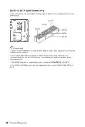
... are SATA 6Gb/s interface ports. However, it is recommended that the flat connector be connected to one SATA device. Each connector can connect to the motherboard for space saving purposes. ∙∙The SATA5 port will be unavailable, when installing M.2 SATA SSD into M2_3. ∙∙The SATA5 and SATA6 ports...
... are SATA 6Gb/s interface ports. However, it is recommended that the flat connector be connected to one SATA device. Each connector can connect to the motherboard for space saving purposes. ∙∙The SATA5 port will be unavailable, when installing M.2 SATA SSD into M2_3. ∙∙The SATA5 and SATA6 ports...
User Manual
Page 40
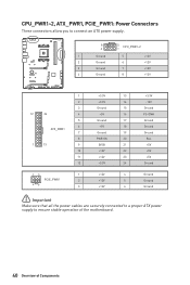
... 6 Ground ⚠⚠Important Make sure that all the power cables are securely connected to a proper ATX power supply to ensure stable operation of the motherboard. 40 Overview of Components
... 6 Ground ⚠⚠Important Make sure that all the power cables are securely connected to a proper ATX power supply to ensure stable operation of the motherboard. 40 Overview of Components
User Manual
Page 45
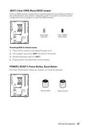
.... 4. Power off the computer and unplug the power cord. 2. If you to power on / reset the computer. Plug the power cord and Power on the motherboard to short JBAT1 for about 5-10 seconds. 3. Keep Data (default) Clear CMOS/ Reset BIOS Resetting BIOS to clear the CMOS memory. Remove the jumper cap...
.... 4. Power off the computer and unplug the power cord. 2. If you to power on / reset the computer. Plug the power cord and Power on the motherboard to short JBAT1 for about 5-10 seconds. 3. Keep Data (default) Clear CMOS/ Reset BIOS Resetting BIOS to clear the CMOS memory. Remove the jumper cap...
User Manual
Page 48
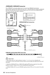
Once all items are connected properly, you to the motherboard specification. ∙∙CORSAIR RGB LED Fan and CORSAIR Lighting Node PRO can control the CORSAIR RGB LED strips and fans with the CORSAIR fan ... work. ∙∙Quantity of Components Please refer to connect the CORSAIR Individually Addressable Lighting PRO RGB LED strips 5V or CORSAIR RGB fans with MSI's software. JCORSAIR1 1 1 +5V 2 3 Ground Data CORSAIR RGB Fan Connection CORSAIR RGB LED fan SATA power SYS_FAN SYS_FAN CORSAIR fan hub 4 5 6 SYS_FAN 3 2 1 SYS_FAN SYS_FAN SYS_FAN CORSAIR...
Once all items are connected properly, you to the motherboard specification. ∙∙CORSAIR RGB LED Fan and CORSAIR Lighting Node PRO can control the CORSAIR RGB LED strips and fans with the CORSAIR fan ... work. ∙∙Quantity of Components Please refer to connect the CORSAIR Individually Addressable Lighting PRO RGB LED strips 5V or CORSAIR RGB fans with MSI's software. JCORSAIR1 1 1 +5V 2 3 Ground Data CORSAIR RGB Fan Connection CORSAIR RGB LED fan SATA power SYS_FAN SYS_FAN CORSAIR fan hub 4 5 6 SYS_FAN 3 2 1 SYS_FAN SYS_FAN SYS_FAN CORSAIR...
User Manual
Page 49
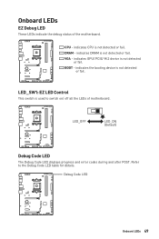
DRAM - Refer to switch on/ off all the LEDs of the motherboard. BOOT - indicates CPU is not detected or fail. indicates DRAM is not detected or fail. indicates the booting device is not detected or fail. Debug ... This switch is used to the Debug Code LED table for details. VGA - Onboard LEDs EZ Debug LED These LEDs indicate the debug status of motherboard. CPU -
DRAM - Refer to switch on/ off all the LEDs of the motherboard. BOOT - indicates CPU is not detected or fail. indicates DRAM is not detected or fail. indicates the booting device is not detected or fail. Debug ... This switch is used to the Debug Code LED table for details. VGA - Onboard LEDs EZ Debug LED These LEDs indicate the debug status of motherboard. CPU -
User Manual
Page 56
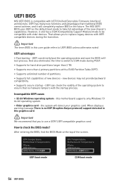
... screen. When display a warning message There is compatible with UEFI (Unified Extensible Firmware Interface) architecture. CPU Temperature: Motherboard Temperature: VCore: DDR Voltage: BIOS Mode: CSM/UEFI UEFI boot mode CPU Temperature: Motherboard Temperature: VCore: DDR Voltage: BIOS Mode: CSM/UEFI CSM boot ...∙∙Fast booting - the system will completely replace BIOS in this motherboard supports only Windows 10 64-bit operating system. ∙∙ Older graphics card - UEFI BIOS MSI UEFI BIOS is no malware tampers with the startup process. this user guide ...
... screen. When display a warning message There is compatible with UEFI (Unified Extensible Firmware Interface) architecture. CPU Temperature: Motherboard Temperature: VCore: DDR Voltage: BIOS Mode: CSM/UEFI UEFI boot mode CPU Temperature: Motherboard Temperature: VCore: DDR Voltage: BIOS Mode: CSM/UEFI CSM boot ...∙∙Fast booting - the system will completely replace BIOS in this motherboard supports only Windows 10 64-bit operating system. ∙∙ Older graphics card - UEFI BIOS MSI UEFI BIOS is no malware tampers with the startup process. this user guide ...
User Manual
Page 58
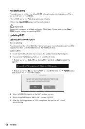
... to reset BIOS: ∙∙Go to BIOS and press F6 to load optimized defaults. ∙∙Short the Clear CMOS jumper on the motherboard. ⚠⚠Important Be sure the computer is 100% completed, the system will reboot automatically. 58 UEFI BIOS And then save the BIOS file...the update file into the USB flash drive. Select a BIOS file to reboot the system. 3. Insert the USB flash drive that matches your motherboard model from MSI website. Please refer to the Clear CMOS jumper section for BIOS update. ▪▪Reboot and press Del key during POST and click on...
... to reset BIOS: ∙∙Go to BIOS and press F6 to load optimized defaults. ∙∙Short the Clear CMOS jumper on the motherboard. ⚠⚠Important Be sure the computer is 100% completed, the system will reboot automatically. 58 UEFI BIOS And then save the BIOS file...the update file into the USB flash drive. Select a BIOS file to reboot the system. 3. Insert the USB flash drive that matches your motherboard model from MSI website. Please refer to the Clear CMOS jumper section for BIOS update. ▪▪Reboot and press Del key during POST and click on...
User Manual
Page 59
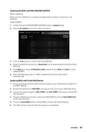
...turned off when the process is 100% completed, the system will restart automatically. Updating BIOS: 1. Please download the latest BIOS file that contains the MSI.ROM file into the Flash BIOS Port on Advance button. 3. Press the Flash BIOS Button to install CPU and memory.) 4. Updating the BIOS with..., and save it to search the latest BIOS file. 4. Select the BIOS file and click on Scan button to the root of your motherboard model from the MSI® website. 2. Plug the USB flash drive that matches your USB flash drive. 3. Select Live Update and click on the rear I/O panel. ...
...turned off when the process is 100% completed, the system will restart automatically. Updating BIOS: 1. Please download the latest BIOS file that contains the MSI.ROM file into the Flash BIOS Port on Advance button. 3. Press the Flash BIOS Button to install CPU and memory.) 4. Updating the BIOS with..., and save it to search the latest BIOS file. 4. Select the BIOS file and click on Scan button to the root of your motherboard model from the MSI® website. 2. Plug the USB flash drive that matches your USB flash drive. 3. Select Live Update and click on the rear I/O panel. ...
User Manual
Page 60
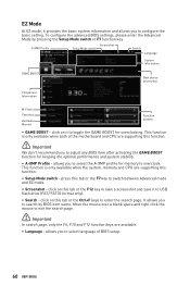
... this tab or the F12 key to take a screenshot and save it to enter the search page. It allows you to select language of the motherboard and CPU are available. ∙∙ Language - allows you to search by pressing the Setup Mode switch or F7 function key. press this function. ∙...
... this tab or the F12 key to take a screenshot and save it to enter the search page. It allows you to select language of the motherboard and CPU are available. ∙∙ Language - allows you to search by pressing the Setup Mode switch or F7 function key. press this function. ∙...
User Manual
Page 61
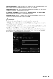
... or disable these buttons. you can move the device icons to enter the Hardware Monitor menu that provides the way to update BIOS with the motherboard you to manually control the fan speed by clicking on the CPU, Memory, Storage, Fan Info and Help buttons to create personal BIOS menu where...
... or disable these buttons. you can move the device icons to enter the Hardware Monitor menu that provides the way to update BIOS with the motherboard you to manually control the fan speed by clicking on the CPU, Memory, Storage, Fan Info and Help buttons to create personal BIOS menu where...
User Manual
Page 63
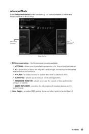
allows you to set the speeds of fans and monitor voltages of installed devices on this motherboard. ∙∙ Menu display - UEFI BIOS 63 BIOS menu selection BIOS menu selection Menu display ∙∙ BIOS menu selection - Increasing the frequency may get ...
allows you to set the speeds of fans and monitor voltages of installed devices on this motherboard. ∙∙ Menu display - UEFI BIOS 63 BIOS menu selection BIOS menu selection Menu display ∙∙ BIOS menu selection - Increasing the frequency may get ...
User Manual
Page 64
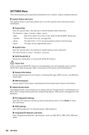
... switch between time elements. The format is not displayed, turn off computer and re-check SATA/ M.2 cable and power cable connections of the device and motherboard. ▶▶System Information Shows detailed system information, including CPU type, BIOS version, and Memory (read only). ▶▶DMI Information Shows system information, desktop...
... switch between time elements. The format is not displayed, turn off computer and re-check SATA/ M.2 cable and power cable connections of the device and motherboard. ▶▶System Information Shows detailed system information, including CPU type, BIOS version, and Memory (read only). ▶▶DMI Information Shows system information, desktop...
User Manual
Page 66
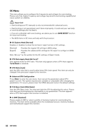
... configure in OC menu will be changed if the processor supports this value. User can only be available when the installed processor, memory modules and motherboard support this function is not guaranteed, and if done improperly, it occurs, please clear the CMOS data and restore the default settings. ▶▶FCH...
... configure in OC menu will be changed if the processor supports this value. User can only be available when the installed processor, memory modules and motherboard support this function is not guaranteed, and if done improperly, it occurs, please clear the CMOS data and restore the default settings. ▶▶FCH...
User Manual
Page 69
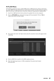
Please download the latest BIOS file that contains the update file into your motherboard model from MSI website, save the BIOS file into the computer. 2. UEFI BIOS 69 Click on M-FLASH tab, a demand message will be prompted. And then follow the steps ...
Please download the latest BIOS file that contains the update file into your motherboard model from MSI website, save the BIOS file into the computer. 2. UEFI BIOS 69 Click on M-FLASH tab, a demand message will be prompted. And then follow the steps ...


