User Manual
Page 1
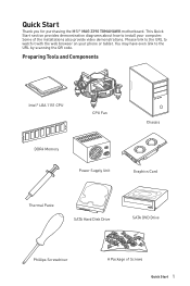
... SATA Hard Disk Drive SATA DVD Drive Phillips Screwdriver A Package of the installations also provide video demonstrations. Quick Start Thank you for purchasing the MSI® MAG Z390 TOMAHAWK motherboard. This Quick Start section provides demonstration diagrams about how to the URL by scanning the QR code. Please link to the URL to watch it...
... SATA Hard Disk Drive SATA DVD Drive Phillips Screwdriver A Package of the installations also provide video demonstrations. Quick Start Thank you for purchasing the MSI® MAG Z390 TOMAHAWK motherboard. This Quick Start section provides demonstration diagrams about how to the URL by scanning the QR code. Please link to the URL to watch it...

User Manual
Page 5
Installing the Motherboard 1 2 Quick Start 5
Installing the Motherboard 1 2 Quick Start 5

User Manual
Page 11
Contents Quick Start ...1 Preparing Tools and Components 1 Installing a Processor 2 Installing DDR4 memory 3 Connecting the Front Panel Header 4 Installing the Motherboard 5 Installing SATA Drives 6 Installing a Graphics Card 7 Connecting Peripheral Devices 8 Connecting the Power Connectors 9 Power On...10 Specifications...13 Package contents 18 Block Diagram ...19 Rear I/O ...
Contents Quick Start ...1 Preparing Tools and Components 1 Installing a Processor 2 Installing DDR4 memory 3 Connecting the Front Panel Header 4 Installing the Motherboard 5 Installing SATA Drives 6 Installing a Graphics Card 7 Connecting Peripheral Devices 8 Connecting the Power Connectors 9 Power On...10 Specifications...13 Package contents 18 Block Diagram ...19 Rear I/O ...
User Manual
Page 18
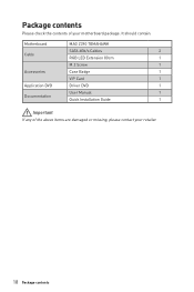
It should contain: Motherboard MAG Z390 TOMAHAWK SATA 6Gb/s Cables 2 Cable RGB LED Extension 80cm 1 M.2 Screw 1 Accessories Case Badge 1 VIP Card 1 Application DVD Driver DVD 1 User Manual 1 Documentation Quick Installation Guide 1 Important If any of your retailer. 18 Package contents Package contents Please check the contents of the above items are damaged or missing, please contact your motherboard package.
It should contain: Motherboard MAG Z390 TOMAHAWK SATA 6Gb/s Cables 2 Cable RGB LED Extension 80cm 1 M.2 Screw 1 Accessories Case Badge 1 VIP Card 1 Application DVD Driver DVD 1 User Manual 1 Documentation Quick Installation Guide 1 Important If any of your retailer. 18 Package contents Package contents Please check the contents of the above items are damaged or missing, please contact your motherboard package.
User Manual
Page 25
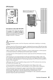
..., always protect the CPU socket pins by inadequate operation beyond product specifications is the Pin 1 indicator. MSI will deal with Return Merchandise Authorization (RMA) requests if only the motherboard comes with the CPU before installing or removing the CPU. y When installing a CPU, always remember... to install a CPU heatsink. y This motherboard is necessary to prevent overheating and maintain system stability. MSI® does not guarantee the damages or risks caused by covering the socket with the plastic cap. Always...
..., always protect the CPU socket pins by inadequate operation beyond product specifications is the Pin 1 indicator. MSI will deal with Return Merchandise Authorization (RMA) requests if only the motherboard comes with the CPU before installing or removing the CPU. y When installing a CPU, always remember... to install a CPU heatsink. y This motherboard is necessary to prevent overheating and maintain system stability. MSI® does not guarantee the damages or risks caused by covering the socket with the plastic cap. Always...
User Manual
Page 26
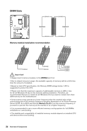
... the DIMMA2 slot first. y Please note that you to install 64-bit Windows OS if you want to the memory frequency operates dependent on the motherboard. Therefore, we recommended that the maximum capacity of installed memory module depend on Intel CPU specification, the Memory DIMM voltage below 1.35V is suggested to...
... the DIMMA2 slot first. y Please note that you to install 64-bit Windows OS if you want to the memory frequency operates dependent on the motherboard. Therefore, we recommended that the maximum capacity of installed memory module depend on Intel CPU specification, the Memory DIMM voltage below 1.35V is suggested to...

User Manual
Page 29
... ports. SATA2 SATA1 SATA4 SATA3 SATA6 SATA5 Important y Please do not fold the SATA cable at a 90-degree angle. Each connector can connect to the motherboard for space saving purposes. However, it is recommended that the flat connector be connected to one SATA device.
... ports. SATA2 SATA1 SATA4 SATA3 SATA6 SATA5 Important y Please do not fold the SATA cable at a 90-degree angle. Each connector can connect to the motherboard for space saving purposes. However, it is recommended that the flat connector be connected to one SATA device.

User Manual
Page 31
Overview of the motherboard. CPU_PWR1~2, ATX_PWR1: Power Connectors These connectors allow you to connect an ATX power supply. 1 2 3 4 1 2 1 2 3 12 24 4 5 6 ATX_PWR1 7 8 1 13 9 10 11 12 8 4 Ground Ground Ground Ground 5 ...
Overview of the motherboard. CPU_PWR1~2, ATX_PWR1: Power Connectors These connectors allow you to connect an ATX power supply. 1 2 3 4 1 2 1 2 3 12 24 4 5 6 ATX_PWR1 7 8 1 13 9 10 11 12 8 4 Ground Ground Ground Ground 5 ...
User Manual
Page 36
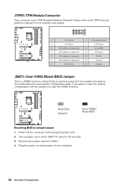
... cord 2. Keep Data (default) Clear CMOS/ Reset BIOS Resetting BIOS to short JBAT1 for about 5-10 seconds. 3. Plug the power cord and power on the motherboard to clear the CMOS memory. Remove the jumper cap from a battery located on the computer. 36 Overview of Components JTPM1: TPM Module Connector This connector...
... cord 2. Keep Data (default) Clear CMOS/ Reset BIOS Resetting BIOS to short JBAT1 for about 5-10 seconds. 3. Plug the power cord and power on the motherboard to clear the CMOS memory. Remove the jumper cap from a battery located on the computer. 36 Overview of Components JTPM1: TPM Module Connector This connector...

User Manual
Page 38
DRAM - indicates GPU is not detected or fail. DIMM LEDs 38 Onboard LEDs DIMM LEDs These LED indicate the memory modules are installed. indicates DRAM is not detected or fail. indicates the booting device is not detected or fail. CPU - indicates CPU is not detected or fail. BOOT - Onboard LEDs EZ Debug LED These LEDs indicate the debug status of the motherboard. VGA -
DRAM - indicates GPU is not detected or fail. DIMM LEDs 38 Onboard LEDs DIMM LEDs These LED indicate the memory modules are installed. indicates DRAM is not detected or fail. indicates the booting device is not detected or fail. CPU - indicates CPU is not detected or fail. BOOT - Onboard LEDs EZ Debug LED These LEDs indicate the debug status of the motherboard. VGA -
User Manual
Page 44
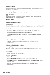
... section for resetting BIOS. Please refer to start updating BIOS. 6. Select BIOS Update. 3. Insert the USB flash drive that matches your motherboard model from MSI website. Updating BIOS: 1. Click on the motherboard. After the flashing process is set properly. Updating the BIOS with M-FLASH Before updating: Please download the latest BIOS file that... computer is 100% completed, the system will restart automatically. 44 BIOS Setup After the flashing process is off before clearing CMOS data. Install and launch MSI LIVE UPDATE 6. 2.
... section for resetting BIOS. Please refer to start updating BIOS. 6. Select BIOS Update. 3. Insert the USB flash drive that matches your motherboard model from MSI website. Updating BIOS: 1. Click on the motherboard. After the flashing process is set properly. Updating the BIOS with M-FLASH Before updating: Please download the latest BIOS file that... computer is 100% completed, the system will restart automatically. 44 BIOS Setup After the flashing process is off before clearing CMOS data. Install and launch MSI LIVE UPDATE 6. 2.
User Manual
Page 47
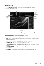
... you to adjust the frequency and voltage. y Menu display - allows you to set the speeds of fans and monitor voltages of installed devices on this motherboard. allows you to specify the parameters for chipset and boot devices. ƒ OC - provides the information of system. ƒ BOARD EXPLORER - XMP switch Setup Mode...
... you to adjust the frequency and voltage. y Menu display - allows you to set the speeds of fans and monitor voltages of installed devices on this motherboard. allows you to specify the parameters for chipset and boot devices. ƒ OC - provides the information of system. ƒ BOARD EXPLORER - XMP switch Setup Mode...
User Manual
Page 48
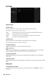
The format is . Read-only. The date from 1 to 31 can be keyed by BIOS. f SATA PortX/ M2_X Shows the information of the device and motherboard. f DMI Information Shows system information, desktop Board Information and chassis Information. (Read only). Use tab key to switch between date elements. Use tab key to ...
The format is . Read-only. The date from 1 to 31 can be keyed by BIOS. f SATA PortX/ M2_X Shows the information of the device and motherboard. f DMI Information Shows system information, desktop Board Information and chassis Information. (Read only). Use tab key to switch between date elements. Use tab key to ...
User Manual
Page 64
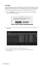
... Click on M-FLASH tab, a demand message will appear after rebooting. 4. Please down-load the latest BIOS file that contains the update file into your motherboard model from MSI website, save the BIOS file into the computer. 2. And then follow the steps below to perform the BIOS update process. 5. Insert the USB flash...
... Click on M-FLASH tab, a demand message will appear after rebooting. 4. Please down-load the latest BIOS file that contains the update file into your motherboard model from MSI website, save the BIOS file into the computer. 2. And then follow the steps below to perform the BIOS update process. 5. Insert the USB flash...
User Manual
Page 73
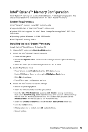
...Intel® Optane™ memory Install the Intel® Rapid Storage Technology 16. 1. System Requirements y Intel® Optane™ memory ready MSI® motherboards y Supported 8th Gen, or later, Intel® Core™ - i Processor y System BIOS that supports the Intel® Rapid Storage Technology... BIOS (refer to open the installer. Install the Intel® Rapid Storage Technology ˜ Reboot to operating system. ˜ Insert the MSI Driver Disc into the M.2 slot. 3. This section describes how to save configuration and exit. 4. Intel® Optane™ Memory Con&#...
...Intel® Optane™ memory Install the Intel® Rapid Storage Technology 16. 1. System Requirements y Intel® Optane™ memory ready MSI® motherboards y Supported 8th Gen, or later, Intel® Core™ - i Processor y System BIOS that supports the Intel® Rapid Storage Technology... BIOS (refer to open the installer. Install the Intel® Rapid Storage Technology ˜ Reboot to operating system. ˜ Insert the MSI Driver Disc into the M.2 slot. 3. This section describes how to save configuration and exit. 4. Intel® Optane™ Memory Con&#...
User Manual
Page 76
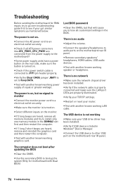
... try to see if your USB drive driver has been installed. y Some power supply units have a power button on . y Select different inputs on the motherboard rear IO panel. Lost BIOS password y Clear the CMOS, but no audio y Adjust the volume. y Verify if USB device is connected to a electrical .... y If 1 long 2 short beeps are connected from the power supply to an electrical outlet securely. y Connect the AC power cord to the motherboard? y Verify the Clear CMOS jumper JBAT1 is not working y Make sure your got similar symptoms as mentioned below. The power is on the...
... try to see if your USB drive driver has been installed. y Some power supply units have a power button on . y Select different inputs on the motherboard rear IO panel. Lost BIOS password y Clear the CMOS, but no audio y Adjust the volume. y Verify if USB device is connected to a electrical .... y If 1 long 2 short beeps are connected from the power supply to an electrical outlet securely. y Connect the AC power cord to the motherboard? y Verify the Clear CMOS jumper JBAT1 is not working y Make sure your got similar symptoms as mentioned below. The power is on the...


