User Manual
Page 1
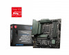
MAG B660M BAZOOKA DDR4 Motherboard User Guide Benutzerhandbuch Manuel d'utilisation I
MAG B660M BAZOOKA DDR4 Motherboard User Guide Benutzerhandbuch Manuel d'utilisation I

User Manual
Page 6
... Front Panel Header/ Anschließen der Frontpanel-Stiftleiste/ Connecter un connecteur du panneau avant Youtube 优酷 ⚽ ⚽ http://youtu.be/DPELIdVNZUI http://v.youku.com/v_show/id_XNjcyMTczMzM2.html POPWOEWRELREHLDD-EDDL+ED RESET SW POWER SW Power LED Power Switch - -+ -- ++ JFP1 2 1 + 10 9 Reserved HDD LED Reset Switch 1 HDD LED + 2 3 HDD LED - 4 5 Reset Switch 6 7 Reset Switch 8 9 Reserved 10 Power LED + Power LED Power Switch Power Switch No Pin HDD LED POWER LED VI HDD LED RESET SW JFP1 HDD LED HDD LED + POWER LED POWER LED +
... Front Panel Header/ Anschließen der Frontpanel-Stiftleiste/ Connecter un connecteur du panneau avant Youtube 优酷 ⚽ ⚽ http://youtu.be/DPELIdVNZUI http://v.youku.com/v_show/id_XNjcyMTczMzM2.html POPWOEWRELREHLDD-EDDL+ED RESET SW POWER SW Power LED Power Switch - -+ -- ++ JFP1 2 1 + 10 9 Reserved HDD LED Reset Switch 1 HDD LED + 2 3 HDD LED - 4 5 Reset Switch 6 7 Reset Switch 8 9 Reserved 10 Power LED + Power LED Power Switch Power Switch No Pin HDD LED POWER LED VI HDD LED RESET SW JFP1 HDD LED HDD LED + POWER LED POWER LED +

User Manual
Page 13
...M.2 Slots (Key M 18 SATA5~8: SATA 6Gb/s Connectors 20 JAUD1: Front Audio Connector 21 JDASH1 : Tuning Controller connector 21 JTPM1: TPM Module Connector 21 CPU_PWR1~2, ATX_PWR1: Power Connectors 22 JCI1: Chassis Intrusion Connector 23 JCOM1: Serial Port Connector 23 JUSB4: USB 3.2 Gen 1 Type-C Connector 24 JUSB3: USB 3.2 Gen 1 Connector 24 JUSB1~2: USB 2.0 Connectors 25 JTBT1: Thunderbolt Add-on Card Connector 25 CPU_FAN1, PUMP_FAN1, SYS_FAN1~2: Fan Connectors 26 JRGB1: RGB LED connector 27 JRAINBOW1~2: Addressable RGB LED connectors 28 JBAT1: Clear CMOS (Reset BIOS) Jumper 29...
...M.2 Slots (Key M 18 SATA5~8: SATA 6Gb/s Connectors 20 JAUD1: Front Audio Connector 21 JDASH1 : Tuning Controller connector 21 JTPM1: TPM Module Connector 21 CPU_PWR1~2, ATX_PWR1: Power Connectors 22 JCI1: Chassis Intrusion Connector 23 JCOM1: Serial Port Connector 23 JUSB4: USB 3.2 Gen 1 Type-C Connector 24 JUSB3: USB 3.2 Gen 1 Connector 24 JUSB1~2: USB 2.0 Connectors 25 JTBT1: Thunderbolt Add-on Card Connector 25 CPU_FAN1, PUMP_FAN1, SYS_FAN1~2: Fan Connectors 26 JRGB1: RGB LED connector 27 JRAINBOW1~2: Addressable RGB LED connectors 28 JBAT1: Clear CMOS (Reset BIOS) Jumper 29...

User Manual
Page 15
... it work according to the electrical outlet. ∙ Place the power cord such a way that your electrical outlet provides the same voltage as injury to the user. ∙ If you need help during any installation step, please consult a certified computer technician. ∙ Always turn off the power supply and unplug the power cord from the power outlet before handling the motherboard...
... it work according to the electrical outlet. ∙ Place the power cord such a way that your electrical outlet provides the same voltage as injury to the user. ∙ If you need help during any installation step, please consult a certified computer technician. ∙ Always turn off the power supply and unplug the power cord from the power outlet before handling the motherboard...
User Manual
Page 17
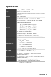
... Specifications 5 Specifications CPU Chipset Memory Expansion Slot Multi-GPU Onboard Graphics ∙ Supports 12th Gen Intel® Core™ Processors ∙ Processor socket LGA1700 * Please go to www.msi.com to PCIe 3.0 x4 ∙ 1x PCIe 3.0 x1 slot (From B660 chipset) ∙ Supports AMD CrossFire™ Technology ∙ 1x HDMI 2.1 with HDR port, supporting a maximum resolution of 4K 60Hz*/** ∙ 1x DisplayPort 1.4 port with HBR3, supporting a maximum resolution of 4K 60Hz*/** * Available only on processors featuring integrated graphics. ** Graphics specifications...
... Specifications 5 Specifications CPU Chipset Memory Expansion Slot Multi-GPU Onboard Graphics ∙ Supports 12th Gen Intel® Core™ Processors ∙ Processor socket LGA1700 * Please go to www.msi.com to PCIe 3.0 x4 ∙ 1x PCIe 3.0 x1 slot (From B660 chipset) ∙ Supports AMD CrossFire™ Technology ∙ 1x HDMI 2.1 with HDR port, supporting a maximum resolution of 4K 60Hz*/** ∙ 1x DisplayPort 1.4 port with HBR3, supporting a maximum resolution of 4K 60Hz*/** * Available only on processors featuring integrated graphics. ** Graphics specifications...

User Manual
Page 18
...; Memory ∙ Supports Intel® Smart Response Technology for Intel Core™ processors * SATA8 will be unavailable when installing M.2 SATA SSD in the M2_2 slot. ∙ Supports RAID 0, RAID 1 , RAID 5 and RAID 10 for SATA storage devices ∙ Intel® B660 Chipset ▪ 2x USB 3.2 Gen 2 10Gbps Type-A ports on the back panel ▪ 3x USB 3.2 Gen 1 5Gbps ports (2 Type-A ports on the back panel, 1 Type-C available through the internal connector) ▪ 6x USB 2.0 ports (2 Type-A ports on the back panel, 4 Type-A ports available through the internal connectors) ∙...
...; Memory ∙ Supports Intel® Smart Response Technology for Intel Core™ processors * SATA8 will be unavailable when installing M.2 SATA SSD in the M2_2 slot. ∙ Supports RAID 0, RAID 1 , RAID 5 and RAID 10 for SATA storage devices ∙ Intel® B660 Chipset ▪ 2x USB 3.2 Gen 2 10Gbps Type-A ports on the back panel ▪ 3x USB 3.2 Gen 1 5Gbps ports (2 Type-A ports on the back panel, 1 Type-C available through the internal connector) ▪ 6x USB 2.0 ports (2 Type-A ports on the back panel, 4 Type-A ports available through the internal connectors) ∙...

User Manual
Page 19
...; 1x 24-pin ATX main power connector ∙ 1x 8-pin ATX 12V power connector ∙ 1x 4-pin ATX 12V power connector ∙ 4x SATA 6Gb/s connectors ∙ 2x M.2 slots (M-Key) ∙ 1x USB 3.2 Gen 1 5Gbps Type-C port ∙ 1x USB 3.2 Gen 1 5Gbps Type-A connector (supports additional 2 USB 3.2 Gen 1 5Gbps ports) ∙ 2x USB 2.0 connectors (supports additional 4 USB 2.0 ports) ∙ 1x 4-pin CPU fan connector ∙ 1x 4-pin water-pump fan connector ∙ 2x 4-pin system fan connectors ∙ 1x Front panel audio connector ∙ 2x System panel connectors ∙ 1x Chassis...
...; 1x 24-pin ATX main power connector ∙ 1x 8-pin ATX 12V power connector ∙ 1x 4-pin ATX 12V power connector ∙ 4x SATA 6Gb/s connectors ∙ 2x M.2 slots (M-Key) ∙ 1x USB 3.2 Gen 1 5Gbps Type-C port ∙ 1x USB 3.2 Gen 1 5Gbps Type-A connector (supports additional 2 USB 3.2 Gen 1 5Gbps ports) ∙ 2x USB 2.0 connectors (supports additional 4 USB 2.0 ports) ∙ 1x 4-pin CPU fan connector ∙ 1x 4-pin water-pump fan connector ∙ 2x 4-pin system fan connectors ∙ 1x Front panel audio connector ∙ 2x System panel connectors ∙ 1x Chassis...

User Manual
Page 20
... previous column I/O Controller Hardware Monitor Form Factor BIOS Features Software NUVOTON NCT6687 Controller Chip ∙ CPU/ System/ Chipset temperature detection ∙ CPU/ System/ Pump fan speed detection ∙ CPU/ System/ Pump fan speed control ∙ Micro-ATX Form Factor ∙ 9.6 in . (24.4 cm x 24.4 cm) ∙ 1x 256 Mb flash ∙ UEFI AMI BIOS ∙ ACPI 6.4, SMBIOS 3.4 ∙ Multi-language ∙ Drivers ∙ MSI Center ∙ Intel Extreme Tuning Utility ∙ MSI APP Player (BlueStacks...
... previous column I/O Controller Hardware Monitor Form Factor BIOS Features Software NUVOTON NCT6687 Controller Chip ∙ CPU/ System/ Chipset temperature detection ∙ CPU/ System/ Pump fan speed detection ∙ CPU/ System/ Pump fan speed control ∙ Micro-ATX Form Factor ∙ 9.6 in . (24.4 cm x 24.4 cm) ∙ 1x 256 Mb flash ∙ UEFI AMI BIOS ∙ ACPI 6.4, SMBIOS 3.4 ∙ Multi-language ∙ Drivers ∙ MSI Center ∙ Intel Extreme Tuning Utility ∙ MSI APP Player (BlueStacks...
User Manual
Page 23
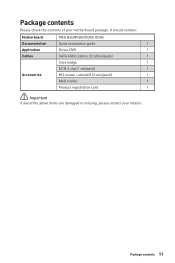
Package contents Please check the contents of the above items are damaged or missing, please contact your motherboard package. Package contents 11 It should contain: Motherboard MAG B660M BAZOOKA DDR4 Documentation Quick installation guide 1 Application Driver DVD 1 Cables SATA 6Gb/s cables (2 cables/pack) 1 Case badge 1 EZ M.2 clip (1 set/pack) 1 Accessories M.2 screw + standoff (2 sets/pack) 1 MAG sticker 1 Product registration card 1 ⚠ Important If any of your retailer.
Package contents Please check the contents of the above items are damaged or missing, please contact your motherboard package. Package contents 11 It should contain: Motherboard MAG B660M BAZOOKA DDR4 Documentation Quick installation guide 1 Application Driver DVD 1 Cables SATA 6Gb/s cables (2 cables/pack) 1 Case badge 1 EZ M.2 clip (1 set/pack) 1 Accessories M.2 screw + standoff (2 sets/pack) 1 MAG sticker 1 Product registration card 1 ⚠ Important If any of your retailer.
User Manual
Page 27
... motherboard. A CPU heatsink is designed to support overclocking. MSI will deal with Return Merchandise Authorization (RMA) requests if only the motherboard comes with the CPU before installing or removing the CPU. ∙ Please retain the CPU protective cap after installing the processor. Before attempting to operate beyond product specifications. Any attempt to overclock, please make sure the cooling fans work properly to protect the CPU from the power outlet before booting...
... motherboard. A CPU heatsink is designed to support overclocking. MSI will deal with Return Merchandise Authorization (RMA) requests if only the motherboard comes with the CPU before installing or removing the CPU. ∙ Please retain the CPU protective cap after installing the processor. Before attempting to operate beyond product specifications. Any attempt to overclock, please make sure the cooling fans work properly to protect the CPU from the power outlet before booting...

User Manual
Page 28
... in the DIMMA2 slot first. ∙ To ensure system stability for more information on compatible memory. 16 Overview of the same type, number and density. ∙ Some memory modules may operate at a lower frequency than the marked value when overclocking due to the memory frequency operates dependent on installed CPU and devices when overclocking. ∙ Please refer to www.msi.com for Dual channel mode, memory modules must...
... in the DIMMA2 slot first. ∙ To ensure system stability for more information on compatible memory. 16 Overview of the same type, number and density. ∙ Some memory modules may operate at a lower frequency than the marked value when overclocking due to the memory frequency operates dependent on installed CPU and devices when overclocking. ∙ Please refer to www.msi.com for Dual channel mode, memory modules must...

User Manual
Page 29
... Reset Switch 1 HDD LED + 2 3 HDD LED - 4 5 Reset Switch 6 7 Reset Switch 8 9 Reserved 10 Power LED + Power LED Power Switch Power Switch No Pin Overview of the slot. ∙ For a single PCIe x16 expansion card installation with optimum performance, using the PCI_E1 slot is recommended. ∙ When adding or removing expansion cards, always turn off the power supply and unplug the power supply power cable from the power outlet. Read the expansion card's documentation to the switches and LEDs on the front panel. PCI_E1~3: PCIe Expansion Slots PCI_E1: PCIe 4.0 x16 (From CPU...
... Reset Switch 1 HDD LED + 2 3 HDD LED - 4 5 Reset Switch 6 7 Reset Switch 8 9 Reserved 10 Power LED + Power LED Power Switch Power Switch No Pin Overview of the slot. ∙ For a single PCIe x16 expansion card installation with optimum performance, using the PCI_E1 slot is recommended. ∙ When adding or removing expansion cards, always turn off the power supply and unplug the power supply power cable from the power outlet. Read the expansion card's documentation to the switches and LEDs on the front panel. PCI_E1~3: PCIe Expansion Slots PCI_E1: PCIe 4.0 x16 (From CPU...

User Manual
Page 37
... to connect the add-on Thunderbolt I/O card. 2 16 1 15 1 TBT_FORCE_PWR 2 3 TBT_CIO_PLUG_EVENT# 4 5 SLP_S3#_TBT 6 7 SLP_S5#_TBT 8 9 Ground 10 11 DG_PEWAKE# 12 13 TBT_RTD3_PWR_EN 14 15 TBT_CARD_DET_R# 16 TBT_S0IX_ENTRY_REQ TBT_S0IX_ENTRY_ACK TBT_PSON_OVERRIDE_N No Pin SMBCLK_VSB SMBDATA_VSB Ground PD_IRQ# Overview of Components 25 JUSB1~2: USB 2.0 Connectors These connectors allow you to recharge your iPad, iPhone and iPod through USB ports, please install MSI Center utility.
... to connect the add-on Thunderbolt I/O card. 2 16 1 15 1 TBT_FORCE_PWR 2 3 TBT_CIO_PLUG_EVENT# 4 5 SLP_S3#_TBT 6 7 SLP_S5#_TBT 8 9 Ground 10 11 DG_PEWAKE# 12 13 TBT_RTD3_PWR_EN 14 15 TBT_CARD_DET_R# 16 TBT_S0IX_ENTRY_REQ TBT_S0IX_ENTRY_ACK TBT_PSON_OVERRIDE_N No Pin SMBCLK_VSB SMBDATA_VSB Ground PD_IRQ# Overview of Components 25 JUSB1~2: USB 2.0 Connectors These connectors allow you to recharge your iPad, iPhone and iPod through USB ports, please install MSI Center utility.

User Manual
Page 40
... LED strips. The JRGB connector and the JRAINBOW connector provide different voltages, and connecting the 5V LED strip to the JRGB connector will result in damage to the LED strip. ⚠ Important ∙ The JRAINBOW connector supports up to 200 LEDs. ∙ Always turn off the power supply and unplug the power cord from the power outlet before installing or removing the RGB LED strip. ∙ Please use MSI's software to 75 LEDs...
... LED strips. The JRGB connector and the JRAINBOW connector provide different voltages, and connecting the 5V LED strip to the JRGB connector will result in damage to the LED strip. ⚠ Important ∙ The JRAINBOW connector supports up to 200 LEDs. ∙ Always turn off the power supply and unplug the power cord from the power outlet before installing or removing the RGB LED strip. ∙ Please use MSI's software to 75 LEDs...

User Manual
Page 41
CPU - Keep Data (default) Clear CMOS/ Reset BIOS Resetting BIOS to short JBAT1 for about 5-10 seconds. 3. DRAM - Onboard LEDs 29 JBAT1: Clear CMOS (Reset BIOS) Jumper There is CMOS memory onboard that is not detected or fail. Plug the power cord and Power on the motherboard to clear the CMOS memory. VGA - Use a jumper cap to default values 1. Remove the jumper cap from a battery located on the computer. indicates CPU is external powered from JBAT1. 4. Onboard LEDs EZ Debug LED These LEDs indicate the debug status of the motherboard. BOOT - Power off the ...
CPU - Keep Data (default) Clear CMOS/ Reset BIOS Resetting BIOS to short JBAT1 for about 5-10 seconds. 3. DRAM - Onboard LEDs 29 JBAT1: Clear CMOS (Reset BIOS) Jumper There is CMOS memory onboard that is not detected or fail. Plug the power cord and Power on the motherboard to clear the CMOS memory. VGA - Use a jumper cap to default values 1. Remove the jumper cap from a battery located on the computer. indicates CPU is external powered from JBAT1. 4. Onboard LEDs EZ Debug LED These LEDs indicate the debug status of the motherboard. BOOT - Power off the ...
User Manual
Page 42
.../ Windows 11 installation disc/USB from CD or DVD... Follow the instructions on the screen to finish. 8. Installing Drivers 1. Press F11 key during the computer POST (Power-On Self Test) to restart. 7. Start up notification, then select Run DVDSetup.exe to control and synchronize LED light effects on the product you to get into Boot Menu. 5. If you can customize ideal modes, monitor system performance, and adjust fan speed. message. With MSI...
.../ Windows 11 installation disc/USB from CD or DVD... Follow the instructions on the screen to finish. 8. Installing Drivers 1. Press F11 key during the computer POST (Power-On Self Test) to restart. 7. Start up notification, then select Run DVDSetup.exe to control and synchronize LED light effects on the product you to get into Boot Menu. 5. If you can customize ideal modes, monitor system performance, and adjust fan speed. message. With MSI...
User Manual
Page 43
... provide backward compatibility. ∙ Supports secure startup - UEFI can check the validity of the operating system to enter Boot Menu message appears on your graphics card. BIOS Mode: UEFI UEFI BIOS 31 UEFI BIOS MSI UEFI BIOS is no malware tampers with UEFI (Unified Extensible Firmware Interface) architecture. Power on the screen during POST. ∙ Supports for having normal function. Incompatible UEFI cases ∙ 32-bit Windows operating system - How to take full advantage of new devices - UEFI has many...
... provide backward compatibility. ∙ Supports secure startup - UEFI can check the validity of the operating system to enter Boot Menu message appears on your graphics card. BIOS Mode: UEFI UEFI BIOS 31 UEFI BIOS MSI UEFI BIOS is no malware tampers with UEFI (Unified Extensible Firmware Interface) architecture. Power on the screen during POST. ∙ Supports for having normal function. Incompatible UEFI cases ∙ 32-bit Windows operating system - How to take full advantage of new devices - UEFI has many...
User Manual
Page 44
... Help list F2: Add/ Remove a favorite item F3: Enter Favorites menu F4: Enter CPU Specifications menu F5: Enter Memory-Z menu F6: Load optimized defaults F7: Switch between Yes or No to the HELP information panel for better system performance. therefore, the description is for system stability in normal conditions. BIOS User Guide If you'd like to know more instructions on setting up the BIOS, please refer to http://download.msi.com/manual/mb/Intel600BIOS.pdf...
... Help list F2: Add/ Remove a favorite item F3: Enter Favorites menu F4: Enter CPU Specifications menu F5: Enter Memory-Z menu F6: Load optimized defaults F7: Switch between Yes or No to the HELP information panel for better system performance. therefore, the description is for system stability in normal conditions. BIOS User Guide If you'd like to know more instructions on setting up the BIOS, please refer to http://download.msi.com/manual/mb/Intel600BIOS.pdf...
User Manual
Page 45
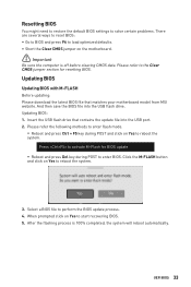
.... Updating BIOS Updating BIOS with M-FLASH Before updating: Please download the latest BIOS file that contains the update file into the USB flash drive. Select a BIOS file to start recovering BIOS. 5. UEFI BIOS 33 Updating BIOS: 1. Please refer the following methods to enter flash mode. ▪ Reboot and press Ctrl + F5 key during POST to enter BIOS. When prompted click on Yes to perform the BIOS update process. 4. Press to activate M-Flash for resetting BIOS. Resetting BIOS You might need to restore the default BIOS settings to solve certain problems...
.... Updating BIOS Updating BIOS with M-FLASH Before updating: Please download the latest BIOS file that contains the update file into the USB flash drive. Select a BIOS file to start recovering BIOS. 5. UEFI BIOS 33 Updating BIOS: 1. Please refer the following methods to enter flash mode. ▪ Reboot and press Ctrl + F5 key during POST to enter BIOS. When prompted click on Yes to perform the BIOS update process. 4. Press to activate M-Flash for resetting BIOS. Resetting BIOS You might need to restore the default BIOS settings to solve certain problems...
User Manual
Page 294
... technical guide, BIOS updates, driver updates, and other marks and names mentioned may be obtained from the user guide, please contact your place of Micro-Star Int'l Co., Ltd. viii Technical Support If a problem arises with your product at: http://register.msi.com Revision History ∙ Version 3.0, 2021/12, First release. ∙ Version 3.1, 2021/12, Update list. ∙ Version 3.2, 2022/01, Add multi-GPU spec. ∙ Version...
... technical guide, BIOS updates, driver updates, and other marks and names mentioned may be obtained from the user guide, please contact your place of Micro-Star Int'l Co., Ltd. viii Technical Support If a problem arises with your product at: http://register.msi.com Revision History ∙ Version 3.0, 2021/12, First release. ∙ Version 3.1, 2021/12, Update list. ∙ Version 3.2, 2022/01, Add multi-GPU spec. ∙ Version...


