User Manual
Page 1
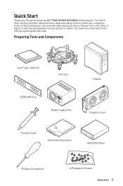
... link to watch it with the web browser on your computer. Please link to the URL to the URL by scanning the QR code. Preparing Tools and Components Intel® LGA 1200 CPU CPU Fan DDR4 Memory Power Supply Unit Chassis Graphics Card Thermal Paste SATA Hard Disk Drive SATA DVD Drive Phillips Screwdriver A Package of the installations also provide video demonstrations. Quick Start Thank you for purchasing the MSI® MAG B560M BAZOOKA motherboard.
... link to watch it with the web browser on your computer. Please link to the URL to the URL by scanning the QR code. Preparing Tools and Components Intel® LGA 1200 CPU CPU Fan DDR4 Memory Power Supply Unit Chassis Graphics Card Thermal Paste SATA Hard Disk Drive SATA DVD Drive Phillips Screwdriver A Package of the installations also provide video demonstrations. Quick Start Thank you for purchasing the MSI® MAG B560M BAZOOKA motherboard.
User Manual
Page 6
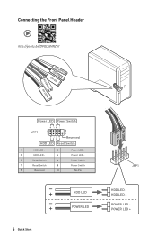
Connecting the Front Panel Header ⚽ ⚽ http://youtu.be/DPELIdVNZUI POPWOEWRELREHLDD-EDDL+ED RESET SW POWER SW Power LED Power Switch - -+ -- ++ JFP1 2 1 + 10 9 Reserved HDD LED Reset Switch 1 HDD LED + 2 3 HDD LED - 4 5 Reset Switch 6 7 Reset Switch 8 9 Reserved 10 Power LED + Power LED Power Switch Power Switch No Pin HDD LED POWER LED 6 Quick Start HDD LED RESET SW JFP1 HDD LED HDD LED + POWER LED POWER LED +
Connecting the Front Panel Header ⚽ ⚽ http://youtu.be/DPELIdVNZUI POPWOEWRELREHLDD-EDDL+ED RESET SW POWER SW Power LED Power Switch - -+ -- ++ JFP1 2 1 + 10 9 Reserved HDD LED Reset Switch 1 HDD LED + 2 3 HDD LED - 4 5 Reset Switch 6 7 Reset Switch 8 9 Reserved 10 Power LED + Power LED Power Switch Power Switch No Pin HDD LED POWER LED 6 Quick Start HDD LED RESET SW JFP1 HDD LED HDD LED + POWER LED POWER LED +
User Manual
Page 13
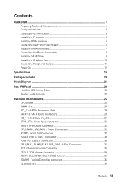
...Start...1 Preparing Tools and Components 1 Safety Information 2 Case stand-off notification 3 Installing a Processor 4 Installing DDR4 memory 5 Connecting the Front Panel Header 6 Installing the Motherboard 7 Connecting the Power Connectors 8 Installing SATA Drives 9 Installing a Graphics Card 10 Connecting Peripheral Devices 11 Power On...12 Specifications...15 Package contents 20 Block Diagram ...21 Rear I/O Panel...22 LAN Port LED Status Table 22 Realtek Audio Console 22 Overview of Components 24 CPU Socket...26 DIMM Slots...27 PCI_E1~3: PCIe Expansion Slots 28 SATA1~6: SATA...
...Start...1 Preparing Tools and Components 1 Safety Information 2 Case stand-off notification 3 Installing a Processor 4 Installing DDR4 memory 5 Connecting the Front Panel Header 6 Installing the Motherboard 7 Connecting the Power Connectors 8 Installing SATA Drives 9 Installing a Graphics Card 10 Connecting Peripheral Devices 11 Power On...12 Specifications...15 Package contents 20 Block Diagram ...21 Rear I/O Panel...22 LAN Port LED Status Table 22 Realtek Audio Console 22 Overview of Components 24 CPU Socket...26 DIMM Slots...27 PCI_E1~3: PCIe Expansion Slots 28 SATA1~6: SATA...
User Manual
Page 14
JRGB1: RGB LED connector 37 JRAINBOW1: Addressable RGB LED connector 38 Installing OS, Drivers & MSI Center 39 Installing Windows® 10 39 Installing Drivers 39 MSI Center...39 UEFI BIOS...40 BIOS Setup...41 Entering BIOS Setup 41 BIOS User Guide...41 Resetting BIOS...42 Updating BIOS...42 Intel® Optane™ Memory Configuration 44 Troubleshooting 45 14 Contents
JRGB1: RGB LED connector 37 JRAINBOW1: Addressable RGB LED connector 38 Installing OS, Drivers & MSI Center 39 Installing Windows® 10 39 Installing Drivers 39 MSI Center...39 UEFI BIOS...40 BIOS Setup...41 Entering BIOS Setup 41 BIOS User Guide...41 Resetting BIOS...42 Updating BIOS...42 Intel® Optane™ Memory Configuration 44 Troubleshooting 45 14 Contents
User Manual
Page 15
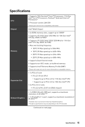
... 2R Max speed up to 4000+ MHz ∙∙Supports Dual-Channel mode ∙∙Supports non-ECC mode, un-buffered memory ∙∙Supports Intel® Extreme Memory Profile (XMP) * Please refer www.msi.com for more information on compatible memory. ∙∙1x PCIe x16 slot ▪▪PCI_E1 (From CPU) ▫▫Supports up to PCIe 4.0 for 11th Gen Intel® CPU ▫▫Supports up to PCIe 3.0 for...
... 2R Max speed up to 4000+ MHz ∙∙Supports Dual-Channel mode ∙∙Supports non-ECC mode, un-buffered memory ∙∙Supports Intel® Extreme Memory Profile (XMP) * Please refer www.msi.com for more information on compatible memory. ∙∙1x PCIe x16 slot ▪▪PCI_E1 (From CPU) ▫▫Supports up to PCIe 4.0 for 11th Gen Intel® CPU ▫▫Supports up to PCIe 3.0 for...
User Manual
Page 16
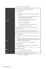
...;2x USB 2.0 Type-A ports on the back panel USB Hubs GL850G ▪▪4x USB 2.0 ports are available through the internal USB 2.0 connectors Realtek® AL897 Codec ▪▪7.1-Channel High Definition Audio ∙∙1x Realtek® RTL8125B 2.5Gbps LAN controller Continued on next page 16 Specifications Storage USB Audio LAN Continued from previous page ∙∙6x SATA 6Gb/s ports (From B560 chipset) ∙∙2x M.2 slots (Key M) ▪▪M2_1 slot ▫▫Supports...
...;2x USB 2.0 Type-A ports on the back panel USB Hubs GL850G ▪▪4x USB 2.0 ports are available through the internal USB 2.0 connectors Realtek® AL897 Codec ▪▪7.1-Channel High Definition Audio ∙∙1x Realtek® RTL8125B 2.5Gbps LAN controller Continued on next page 16 Specifications Storage USB Audio LAN Continued from previous page ∙∙6x SATA 6Gb/s ports (From B560 chipset) ∙∙2x M.2 slots (Key M) ▪▪M2_1 slot ▫▫Supports...
User Manual
Page 17
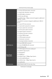
... ATX main power connector ∙∙1x 8-pin ATX 12V power connector ∙∙6x SATA 6Gb/s connectors ∙∙2x M.2 slots (M-Key) ∙∙1x USB 3.2 Gen 1 5Gbps connector (supports additional 2 USB Gen 1 ports) ∙∙2x USB 2.0 connectors (supports additional 4 USB 2.0 ports) ∙∙1x 4-pin CPU fan connector ∙∙1x 4-pin water-pump fan connector ∙∙2x 4-pin system fan connectors ∙∙1x Front panel audio connector ∙∙2x System panel connectors ∙∙1x Chassis Intrusion connector ∙∙1x Clear CMOS...
... ATX main power connector ∙∙1x 8-pin ATX 12V power connector ∙∙6x SATA 6Gb/s connectors ∙∙2x M.2 slots (M-Key) ∙∙1x USB 3.2 Gen 1 5Gbps connector (supports additional 2 USB Gen 1 ports) ∙∙2x USB 2.0 connectors (supports additional 4 USB 2.0 ports) ∙∙1x 4-pin CPU fan connector ∙∙1x 4-pin water-pump fan connector ∙∙2x 4-pin system fan connectors ∙∙1x Front panel audio connector ∙∙2x System panel connectors ∙∙1x Chassis Intrusion connector ∙∙1x Clear CMOS...
User Manual
Page 18
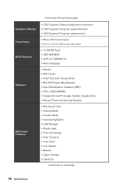
... Hardware Monitor Form Factor BIOS Features Software MSI Center Features ∙∙CPU/ System/ Chipset temperature detection ∙∙CPU/ System/ Pump fan speed detection ∙∙CPU/ System/ Pump fan speed control ∙∙Micro-ATX Form Factor ∙∙9.6 in . (24.4 cm x 24.4 cm) ∙∙1x 256 Mb flash ∙∙UEFI AMI BIOS ∙∙ACPI 6.2, SMBIOS 3.0 ∙∙ Multi-language ∙∙ Drivers ∙∙MSI...
... Hardware Monitor Form Factor BIOS Features Software MSI Center Features ∙∙CPU/ System/ Chipset temperature detection ∙∙CPU/ System/ Pump fan speed detection ∙∙CPU/ System/ Pump fan speed control ∙∙Micro-ATX Form Factor ∙∙9.6 in . (24.4 cm x 24.4 cm) ∙∙1x 256 Mb flash ∙∙UEFI AMI BIOS ∙∙ACPI 6.2, SMBIOS 3.0 ∙∙ Multi-language ∙∙ Drivers ∙∙MSI...
User Manual
Page 20
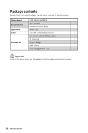
It should contain: Motherboard MAG B560M BAZOOKA User manual 1 Documentation Quick installation guide 1 Application Driver DVD 1 Cable SATA 6G cables (2 cables/pack) 1 M.2 screw + standoff (2 sets/pack) 1 IO shielding 1 Accessories Dragon Badge 1 MAG sticker 1 Product registration card 1 ⚠⚠Important If any of your retailer. 20 Package contents Package contents Please check the contents of the above items are damaged or missing, please contact your motherboard package.
It should contain: Motherboard MAG B560M BAZOOKA User manual 1 Documentation Quick installation guide 1 Application Driver DVD 1 Cable SATA 6G cables (2 cables/pack) 1 M.2 screw + standoff (2 sets/pack) 1 IO shielding 1 Accessories Dragon Badge 1 MAG sticker 1 Product registration card 1 ⚠⚠Important If any of your retailer. 20 Package contents Package contents Please check the contents of the above items are damaged or missing, please contact your motherboard package.
User Manual
Page 26
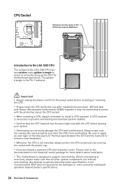
... enhance heat dissipation. ∙∙Whenever the CPU is not installed, always protect the CPU socket pins by inadequate operation beyond product specifications is not recommended. Before attempting to overclock, please make sure the cooling fans work properly to protect the CPU from the power outlet before booting your system. ∙∙Overheating can tolerate overclocking. MSI® does not guarantee the damages or...
... enhance heat dissipation. ∙∙Whenever the CPU is not installed, always protect the CPU socket pins by inadequate operation beyond product specifications is not recommended. Before attempting to overclock, please make sure the cooling fans work properly to protect the CPU from the power outlet before booting your system. ∙∙Overheating can tolerate overclocking. MSI® does not guarantee the damages or...
User Manual
Page 27
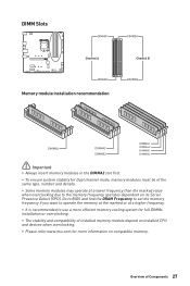
... memory frequency operates dependent on compatible memory. DIMM Slots DIMMA1 DIMMB1 Channel A Channel B DIMMA2 Memory module installation recommendation DIMMB2 DIMMA2 DIMMA2 DIMMB2 DIMMA1 DIMMA2 DIMMB1 DIMMB2 ⚠⚠Important ∙∙Always insert memory modules in the DIMMA2 slot first. ∙∙To ensure system stability for Dual channel mode, memory modules must be of installed memory module depend on installed CPU and devices when overclocking. ∙∙Please refer www.msi...
... memory frequency operates dependent on compatible memory. DIMM Slots DIMMA1 DIMMB1 Channel A Channel B DIMMA2 Memory module installation recommendation DIMMB2 DIMMA2 DIMMA2 DIMMB2 DIMMA1 DIMMA2 DIMMB1 DIMMB2 ⚠⚠Important ∙∙Always insert memory modules in the DIMMA2 slot first. ∙∙To ensure system stability for Dual channel mode, memory modules must be of installed memory module depend on installed CPU and devices when overclocking. ∙∙Please refer www.msi...
User Manual
Page 29
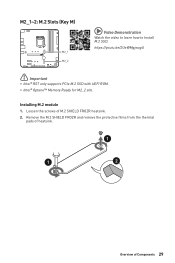
Installing M.2 module 1. Loosen the screws of Components 29 Remove the M.2 SHIELD FROZR and remove the protective films from the thermal pads of heatsink. 1 1 2 Overview of M.2 SHIELD FROZR heatsink. 2. M2_1~2: M.2 Slots (Key M) M2_1 M2_2 ⚽⚽Video Demonstration Watch the video to learn how to Install M.2 SSD. https://youtu.be/2UeWMgjwogU ⚠⚠Important ∙∙Intel® RST only supports PCIe M.2 SSD with UEFI ROM. ∙∙Intel® Optane™ Memory Ready for M2_2 slto.
Installing M.2 module 1. Loosen the screws of Components 29 Remove the M.2 SHIELD FROZR and remove the protective films from the thermal pads of heatsink. 1 1 2 Overview of M.2 SHIELD FROZR heatsink. 2. M2_1~2: M.2 Slots (Key M) M2_1 M2_2 ⚽⚽Video Demonstration Watch the video to learn how to Install M.2 SSD. https://youtu.be/2UeWMgjwogU ⚠⚠Important ∙∙Intel® RST only supports PCIe M.2 SSD with UEFI ROM. ∙∙Intel® Optane™ Memory Ready for M2_2 slto.
User Manual
Page 36
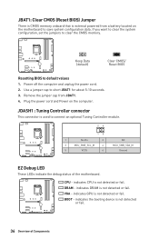
... fail. JBAT1: Clear CMOS (Reset BIOS) Jumper There is CMOS memory onboard that is external powered from JBAT1. 4. JDASH1 : Tuning Controller connector This connector is not detected or fail. Keep Data (default) Clear CMOS/ Reset BIOS Resetting BIOS to short JBAT1 for about 5-10 seconds. 3. indicates DRAM is used to clear the CMOS memory. Remove the jumper cap from a battery located on the computer. BOOT - If you want to clear the system configuration, set the jumpers to connect an optional Tuning Controller module. 26 15 1 No Pin 2 3 MCU_SMB_SCL_M...
... fail. JBAT1: Clear CMOS (Reset BIOS) Jumper There is CMOS memory onboard that is external powered from JBAT1. 4. JDASH1 : Tuning Controller connector This connector is not detected or fail. Keep Data (default) Clear CMOS/ Reset BIOS Resetting BIOS to short JBAT1 for about 5-10 seconds. 3. indicates DRAM is used to clear the CMOS memory. Remove the jumper cap from a battery located on the computer. BOOT - If you want to clear the system configuration, set the jumpers to connect an optional Tuning Controller module. 26 15 1 No Pin 2 3 MCU_SMB_SCL_M...
User Manual
Page 38
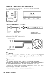
... the power outlet before installing or removing the RGB LED strip. ∙∙Please use MSI's software to control the extended LED strip. 38 Overview of LED strips. In the case of 20% brightness, the connector supports up to connect the WS2812B Individually Addressable RGB LED strips 5V. 1 JRAINBOW1 1 +5V 2 Data 3 No Pin 4 Ground Addressable RGB LED Strip Connection 1 +5V D JRAINBOW connector Rainbow RGB LED extension cable Addressable RGB LED Fan Connection JRAINBOW connector 1 WS2812B...
... the power outlet before installing or removing the RGB LED strip. ∙∙Please use MSI's software to control the extended LED strip. 38 Overview of LED strips. In the case of 20% brightness, the connector supports up to connect the WS2812B Individually Addressable RGB LED strips 5V. 1 JRAINBOW1 1 +5V 2 Data 3 No Pin 4 Ground Addressable RGB LED Strip Connection 1 +5V D JRAINBOW connector Rainbow RGB LED extension cable Addressable RGB LED Fan Connection JRAINBOW connector 1 WS2812B...
User Manual
Page 39
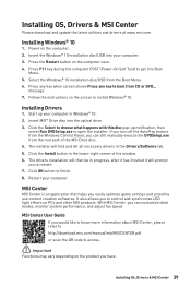
... QR code to restart. 7. Click OK button to install Windows® 10. Select the Windows® 10 installation disc/USB from CD or DVD... Insert MSI® Drive disc into your computer. 3. Restart your computer in the Drivers/Software tab. 5. message. 7. MSI Center User Guide If you have. Installing Drivers 1. Installing OS, Drivers & MSI Center 39 Power on the computer case. 4. If you turn off the AutoPlay feature from the Windows Control Panel, you to access. ⚠...
... QR code to restart. 7. Click OK button to install Windows® 10. Select the Windows® 10 installation disc/USB from CD or DVD... Insert MSI® Drive disc into your computer. 3. Restart your computer in the Drivers/Software tab. 5. message. 7. MSI Center User Guide If you have. Installing Drivers 1. Installing OS, Drivers & MSI Center 39 Power on the computer case. 4. If you turn off the AutoPlay feature from the Windows Control Panel, you to access. ⚠...
User Manual
Page 41
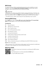
... information panel for better system performance. You should be slightly different from the latest BIOS and should always keep the default settings to confirm your system. UEFI BIOS 41 BIOS User Guide If you'd like to know more instructions on setting up the BIOS, please refer to http://download.msi.com/manual/mb/Intel500BIOS.pdf or scan the QR code to enter Boot Menu message appears on your choice. BIOS Setup The default settings...
... information panel for better system performance. You should be slightly different from the latest BIOS and should always keep the default settings to confirm your system. UEFI BIOS 41 BIOS User Guide If you'd like to know more instructions on setting up the BIOS, please refer to http://download.msi.com/manual/mb/Intel500BIOS.pdf or scan the QR code to enter Boot Menu message appears on your choice. BIOS Setup The default settings...
User Manual
Page 42
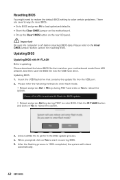
... POST and click on Yes to enter BIOS. Updating BIOS Updating BIOS with M-FLASH Before updating: Please download the latest BIOS file that contains the update file into the USB flash drive. Resetting BIOS You might need to restore the default BIOS setting to solve certain problems. There are several ways to reset BIOS: ∙∙Go to BIOS and press F6 to load optimized defaults. ∙∙Short the Clear CMOS jumper on the motherboard. ∙∙Press the Clear CMOS button on the rear I/O panel...
... POST and click on Yes to enter BIOS. Updating BIOS Updating BIOS with M-FLASH Before updating: Please download the latest BIOS file that contains the update file into the USB flash drive. Resetting BIOS You might need to restore the default BIOS setting to solve certain problems. There are several ways to reset BIOS: ∙∙Go to BIOS and press F6 to load optimized defaults. ∙∙Short the Clear CMOS jumper on the motherboard. ∙∙Press the Clear CMOS button on the rear I/O panel...
User Manual
Page 44
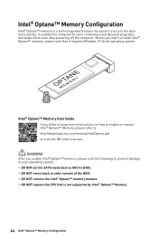
... set the SATA mode back to AHCI in BIOS. ∙∙ DO NOT revert back to access the data more quickly. Intel® Optane™ Memory User Guide If you'd like to know more instructions on how to enable or remove Intel® Optane™ Memory, please refer to http://download.msi.com/manual/mb/Optane.pdf or scan the QR code to access. ⚠⚠WARNING After you start...
... set the SATA mode back to AHCI in BIOS. ∙∙ DO NOT revert back to access the data more quickly. Intel® Optane™ Memory User Guide If you'd like to know more instructions on how to enable or remove Intel® Optane™ Memory, please refer to http://download.msi.com/manual/mb/Optane.pdf or scan the QR code to access. ⚠⚠WARNING After you start...
User Manual
Page 45
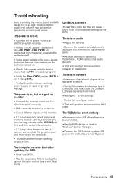
... known working graphics card. There is no network ∙∙Make sure the network chipset driver has been installed. ∙∙Verify if the network cable is properly connected and make sure the LAN port LEDs are connected from the power supply to the motherboard? ∙∙Some power supply units have a power button on the rear side, make sure the button is turned on. ∙∙Check if the power switch cable is connected to JFP1 pin header properly...
... known working graphics card. There is no network ∙∙Make sure the network chipset driver has been installed. ∙∙Verify if the network cable is properly connected and make sure the LAN port LEDs are connected from the power supply to the motherboard? ∙∙Some power supply units have a power button on the rear side, make sure the button is turned on. ∙∙Check if the power switch cable is connected to JFP1 pin header properly...
User Manual
Page 50
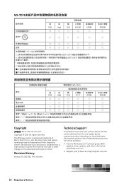
The MSI logo used is expressed or implied. No warranty as to this document without prior notice. Technical Support If a problem arises with your system and no solution can be trademarks of purchase or local distributor. Copyright © 2021 All rights reserved. Alternatively, please try the following help resources for technical guide, BIOS updates, driver updates, and other marks and names...
The MSI logo used is expressed or implied. No warranty as to this document without prior notice. Technical Support If a problem arises with your system and no solution can be trademarks of purchase or local distributor. Copyright © 2021 All rights reserved. Alternatively, please try the following help resources for technical guide, BIOS updates, driver updates, and other marks and names...


