User Manual
Page 1
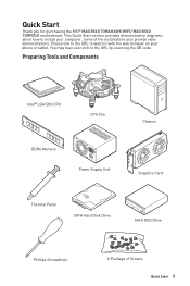
... you for purchasing the MSI® MAG B560 TOMAHAWK WIFI/ MAG B560 TORPEDO motherboard. Please link to the URL to the URL by scanning the QR code. Preparing Tools and Components Intel® LGA1200 CPU CPU Fan DDR4 Memory Power Supply Unit Chassis Graphics Card Thermal Paste SATA Hard Disk Drive SATA DVD Drive Phillips Screwdriver A Package of the installations also provide video demonstrations. You may have even link to watch it with the web browser...
... you for purchasing the MSI® MAG B560 TOMAHAWK WIFI/ MAG B560 TORPEDO motherboard. Please link to the URL to the URL by scanning the QR code. Preparing Tools and Components Intel® LGA1200 CPU CPU Fan DDR4 Memory Power Supply Unit Chassis Graphics Card Thermal Paste SATA Hard Disk Drive SATA DVD Drive Phillips Screwdriver A Package of the installations also provide video demonstrations. You may have even link to watch it with the web browser...

User Manual
Page 6
Connecting the Front Panel Header ⚽ ⚽ http://youtu.be/DPELIdVNZUI POPWOEWRELREHLDD-EDDL+ED RESET SW POWER SW Power LED Power Switch - -+ -- ++ JFP1 2 1 + 10 9 Reserved HDD LED Reset Switch 1 HDD LED + 2 3 HDD LED - 4 5 Reset Switch 6 7 Reset Switch 8 9 Reserved 10 Power LED + Power LED Power Switch Power Switch No Pin HDD LED POWER LED 6 Quick Start HDD LED RESET SW JFP1 HDD LED HDD LED + POWER LED POWER LED +
Connecting the Front Panel Header ⚽ ⚽ http://youtu.be/DPELIdVNZUI POPWOEWRELREHLDD-EDDL+ED RESET SW POWER SW Power LED Power Switch - -+ -- ++ JFP1 2 1 + 10 9 Reserved HDD LED Reset Switch 1 HDD LED + 2 3 HDD LED - 4 5 Reset Switch 6 7 Reset Switch 8 9 Reserved 10 Power LED + Power LED Power Switch Power Switch No Pin HDD LED POWER LED 6 Quick Start HDD LED RESET SW JFP1 HDD LED HDD LED + POWER LED POWER LED +

User Manual
Page 14
... Processor 4 Installing DDR4 memory 5 Connecting the Front Panel Header 6 Installing the Motherboard 7 Connecting the Power Connectors 8 Installing SATA Drives 9 Installing a Graphics Card 10 Connecting Peripheral Devices 11 Power On...13 Specifications...16 Package contents 23 Block Diagram ...24 Rear I/O Panel...25 LAN Port LED Status Table 26 Audio Ports Configuration 26 Realtek Audio Console 26 Overview of Components 30 CPU Socket...32 DIMM Slots...33 PCI_E1~3: PCIe Expansion Slots 34 JAUD1: Front Audio Connector 34 M2_1~3: M.2 Slots (Key M 35 SATA1~6: SATA 6Gb/s Connectors...
... Processor 4 Installing DDR4 memory 5 Connecting the Front Panel Header 6 Installing the Motherboard 7 Connecting the Power Connectors 8 Installing SATA Drives 9 Installing a Graphics Card 10 Connecting Peripheral Devices 11 Power On...13 Specifications...16 Package contents 23 Block Diagram ...24 Rear I/O Panel...25 LAN Port LED Status Table 26 Audio Ports Configuration 26 Realtek Audio Console 26 Overview of Components 30 CPU Socket...32 DIMM Slots...33 PCI_E1~3: PCIe Expansion Slots 34 JAUD1: Front Audio Connector 34 M2_1~3: M.2 Slots (Key M 35 SATA1~6: SATA 6Gb/s Connectors...

User Manual
Page 15
JDASH1 : Tuning Controller connector 44 JRGB1~2: RGB LED connectors 45 JRAINBOW1~2: Addressable RGB LED connectors 46 Onboard LEDs...47 EZ Debug LED...47 LED_SW1: EZ LED Control 47 Installing OS, Drivers & MSI Center 48 Installing Windows® 10 48 Installing Drivers 48 MSI Center...48 UEFI BIOS...49 BIOS Setup...50 Entering BIOS Setup 50 BIOS User Guide...50 Resetting BIOS...51 Updating BIOS...51 Intel® Optane™ Memory Configuration 53 Troubleshooting 54 Contents 15
JDASH1 : Tuning Controller connector 44 JRGB1~2: RGB LED connectors 45 JRAINBOW1~2: Addressable RGB LED connectors 46 Onboard LEDs...47 EZ Debug LED...47 LED_SW1: EZ LED Control 47 Installing OS, Drivers & MSI Center 48 Installing Windows® 10 48 Installing Drivers 48 MSI Center...48 UEFI BIOS...49 BIOS Setup...50 Entering BIOS Setup 50 BIOS User Guide...50 Resetting BIOS...51 Updating BIOS...51 Intel® Optane™ Memory Configuration 53 Troubleshooting 54 Contents 15
User Manual
Page 16
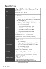
... on next column 16 Specifications Continued on compatible memory ∙∙2x PCIe x16 slots ▪▪PCI_E1 (from B560 chipset) ∙∙Supports 2-Way AMD® CrossFire™ Technology ∙∙1x HDMI 2.0b with HDR port, supports a maximum resolution of 4K 60Hz*/** ∙∙1x DisplayPort 1.4 port, supports a maximum resolution of 4K 60Hz*/** * Available only on processors featuring integrated graphics. ** Graphics specifications may vary depending on the CPU installed.
... on next column 16 Specifications Continued on compatible memory ∙∙2x PCIe x16 slots ▪▪PCI_E1 (from B560 chipset) ∙∙Supports 2-Way AMD® CrossFire™ Technology ∙∙1x HDMI 2.0b with HDR port, supports a maximum resolution of 4K 60Hz*/** ∙∙1x DisplayPort 1.4 port, supports a maximum resolution of 4K 60Hz*/** * Available only on processors featuring integrated graphics. ** Graphics specifications may vary depending on the CPU installed.

User Manual
Page 17
...; Memory Ready** ∙∙Supports Intel® Smart Response Technology for Intel Core™ processors * SATA1 will be unavailable when installing M.2 SATA SSD in the M2_2 slot. ** Before using Intel® Optane™ memory modules, please ensure that you have updated the drivers and BIOS to the latest version from MSI website. ∙∙Intel® B560 Chipset ▪▪1x USB3.2 Gen 2x2 20Gbps port (Type-C port on the back panel...
...; Memory Ready** ∙∙Supports Intel® Smart Response Technology for Intel Core™ processors * SATA1 will be unavailable when installing M.2 SATA SSD in the M2_2 slot. ** Before using Intel® Optane™ memory modules, please ensure that you have updated the drivers and BIOS to the latest version from MSI website. ∙∙Intel® B560 Chipset ▪▪1x USB3.2 Gen 2x2 20Gbps port (Type-C port on the back panel...
User Manual
Page 18
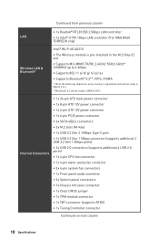
... power connector ∙∙1x 6-pin PCIE power connector ∙∙6x SATA 6Gb/s connectors ∙∙3x M.2 slots (M-Key) ∙∙1x USB 3.2 Gen 2 10Gbps Type-C port ∙∙1x USB 3.2 Gen 1 5Gbps connector (supports additional 2 USB 3.2 Gen 1 5Gbps ports) ∙∙2x USB 2.0 connectors (supports additional 4 USB 2.0 ports) ∙∙1x 4-pin CPU fan connector ∙∙1x 4-pin water-pump fan connector ∙∙5x 4-pin system fan connectors ∙∙1x Front panel audio connector ∙∙2x System panel connectors ∙∙1x Chassis...
... power connector ∙∙1x 6-pin PCIE power connector ∙∙6x SATA 6Gb/s connectors ∙∙3x M.2 slots (M-Key) ∙∙1x USB 3.2 Gen 2 10Gbps Type-C port ∙∙1x USB 3.2 Gen 1 5Gbps connector (supports additional 2 USB 3.2 Gen 1 5Gbps ports) ∙∙2x USB 2.0 connectors (supports additional 4 USB 2.0 ports) ∙∙1x 4-pin CPU fan connector ∙∙1x 4-pin water-pump fan connector ∙∙5x 4-pin system fan connectors ∙∙1x Front panel audio connector ∙∙2x System panel connectors ∙∙1x Chassis...
User Manual
Page 19
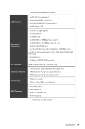
... USB 3.2 Gen 2x2 20Gbps Type-C port ∙∙1x 2.5G LAN (RJ45) port ∙∙1x 1G LAN (RJ45) port (For MAG B560 TORPEDO only) ∙∙2x Wi-Fi Antenna connectors (For MAG B560 TOMAHAWK WIFI only) ∙∙5x audio jacks ∙∙1x Optical S/PDIF OUT connector NUVOTON NCT6687-R Controller Chip ∙∙CPU/ System/ Chipset temperature detection ∙∙CPU/ System/ Pump fan speed detection ∙∙CPU/ System/ Pump fan speed control...
... USB 3.2 Gen 2x2 20Gbps Type-C port ∙∙1x 2.5G LAN (RJ45) port ∙∙1x 1G LAN (RJ45) port (For MAG B560 TORPEDO only) ∙∙2x Wi-Fi Antenna connectors (For MAG B560 TOMAHAWK WIFI only) ∙∙5x audio jacks ∙∙1x Optical S/PDIF OUT connector NUVOTON NCT6687-R Controller Chip ∙∙CPU/ System/ Chipset temperature detection ∙∙CPU/ System/ Pump fan speed detection ∙∙CPU/ System/ Pump fan speed control...
User Manual
Page 23
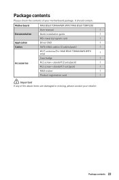
... of the above items are damaged or missing, please contact your motherboard package. It should contain: Motherboard Documentation Application Cables Accessories MAG B560 TOMAHAWK WIFI/ MAG B560 TORPEDO User manual 1 Quick installation guide 1 MSI reward program card 1 Driver DVD 1 SATA 6Gb/s cables (2 cables/pack) 1 Wi-Fi antenna (For MAG B560 TOMAHAWK WIFII only) 1 Case badge 1 M.2 screw + standoff (2 sets/pack) 1 M.2 screw + standoff (1 set/pack) 1 MAG sticker 1 Product registration card 1 ⚠⚠Important If any of your retailer.
... of the above items are damaged or missing, please contact your motherboard package. It should contain: Motherboard Documentation Application Cables Accessories MAG B560 TOMAHAWK WIFI/ MAG B560 TORPEDO User manual 1 Quick installation guide 1 MSI reward program card 1 Driver DVD 1 SATA 6Gb/s cables (2 cables/pack) 1 Wi-Fi antenna (For MAG B560 TOMAHAWK WIFII only) 1 Case badge 1 M.2 screw + standoff (2 sets/pack) 1 M.2 screw + standoff (1 set/pack) 1 MAG sticker 1 Product registration card 1 ⚠⚠Important If any of your retailer.

User Manual
Page 32
... with the CPU before installing or removing the CPU. ∙∙Please retain the CPU protective cap after installing the processor. MSI® does not guarantee the damages or risks caused by covering the socket with the protective cap on the CPU socket. ∙∙When installing a CPU, always remember to assist in the heatsink/ cooler package for motherboard placement. Before attempting to support overclocking. The golden...
... with the CPU before installing or removing the CPU. ∙∙Please retain the CPU protective cap after installing the processor. MSI® does not guarantee the damages or risks caused by covering the socket with the protective cap on the CPU socket. ∙∙When installing a CPU, always remember to assist in the heatsink/ cooler package for motherboard placement. Before attempting to support overclocking. The golden...

User Manual
Page 34
... slot. ∙∙For a single PCIe x16 expansion card installation with optimum performance, using the PCI_E1 slot is recommended. ∙∙When adding or removing expansion cards, always turn off the power supply and unplug the power supply power cable from the power outlet. PCI_E1~3: PCIe Expansion Slots PCI_E1: PCIe 4.0 x16 (From CPU) BAT1 PCI_E2: PCIe 3.0 x4 (From B560 chipset) PCI_E3: PCIe 3.0 x1 (From B560 chipset) ⚠⚠Important ∙∙If you install a large and heavy graphics card...
... slot. ∙∙For a single PCIe x16 expansion card installation with optimum performance, using the PCI_E1 slot is recommended. ∙∙When adding or removing expansion cards, always turn off the power supply and unplug the power supply power cable from the power outlet. PCI_E1~3: PCIe Expansion Slots PCI_E1: PCIe 4.0 x16 (From CPU) BAT1 PCI_E2: PCIe 3.0 x4 (From B560 chipset) PCI_E3: PCIe 3.0 x1 (From B560 chipset) ⚠⚠Important ∙∙If you install a large and heavy graphics card...

User Manual
Page 44
... a battery located on the computer. JDASH1 : Tuning Controller connector This connector is external powered from JBAT1. 4. Power off the computer and unplug the power cord. 2. JBAT1: Clear CMOS (Reset BIOS) Jumper There is CMOS memory onboard that is used to short JBAT1 for about 5-10 seconds. 3. Keep Data (default) Clear CMOS/ Reset BIOS Resetting BIOS to save system configuration data. Plug the power cord and Power on the motherboard to default values 1. If you want to clear the system configuration, set the jumpers to clear the CMOS memory.
... a battery located on the computer. JDASH1 : Tuning Controller connector This connector is external powered from JBAT1. 4. Power off the computer and unplug the power cord. 2. JBAT1: Clear CMOS (Reset BIOS) Jumper There is CMOS memory onboard that is used to short JBAT1 for about 5-10 seconds. 3. Keep Data (default) Clear CMOS/ Reset BIOS Resetting BIOS to save system configuration data. Plug the power cord and Power on the motherboard to default values 1. If you want to clear the system configuration, set the jumpers to clear the CMOS memory.

User Manual
Page 46
... power supply and unplug the power cord from the power outlet before installing or removing the RGB LED strip. ∙∙Please use MSI's software to control the extended LED strip. 46 Overview of LED strips. In the case of 20% brightness, the connector supports up to connect the WS2812B Individually Addressable RGB LED strips 5V. 1 1 +5V 2 Data 3 No Pin 4 Ground Addressable RGB LED Strip Connection 1 +5V D JRAINBOW connector Rainbow RGB LED extension cable...
... power supply and unplug the power cord from the power outlet before installing or removing the RGB LED strip. ∙∙Please use MSI's software to control the extended LED strip. 46 Overview of LED strips. In the case of 20% brightness, the connector supports up to connect the WS2812B Individually Addressable RGB LED strips 5V. 1 1 +5V 2 Data 3 No Pin 4 Ground Addressable RGB LED Strip Connection 1 +5V D JRAINBOW connector Rainbow RGB LED extension cable...
User Manual
Page 48
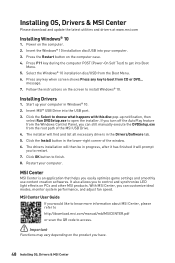
... Windows Control Panel, you can still manually execute the DVDSetup.exe from the Boot Menu. 6. Press the Restart button on the screen to open the installer. With MSI Center, you can customize ideal modes, monitor system performance, and adjust fan speed. Installing OS, Drivers & MSI Center Please download and update the latest utilities and drivers at www.msi.com Installing Windows® 10 1. The drivers installation will prompt you easily optimize game settings and smoothly use content creation softwares. Power...
... Windows Control Panel, you can still manually execute the DVDSetup.exe from the Boot Menu. 6. Press the Restart button on the screen to open the installer. With MSI Center, you can customize ideal modes, monitor system performance, and adjust fan speed. Installing OS, Drivers & MSI Center Please download and update the latest utilities and drivers at www.msi.com Installing Windows® 10 1. The drivers installation will prompt you easily optimize game settings and smoothly use content creation softwares. Power...

User Manual
Page 49
... user guide refers to CSM mode during the boot process. 3. When display a warning message There is compatible with the startup process. After entering the BIOS, you to check the BIOS mode? 1. How to replace with a GOP/UEFI compatible graphics card or using integrated graphics from CPU for hard drive partitions larger than 2 TB. ∙∙Supports more than 4 primary partitions with UEFI firmware architecture. ⚠⚠Important The term BIOS in this motherboard supports only 64-bit Windows...
... user guide refers to CSM mode during the boot process. 3. When display a warning message There is compatible with the startup process. After entering the BIOS, you to check the BIOS mode? 1. How to replace with a GOP/UEFI compatible graphics card or using integrated graphics from CPU for hard drive partitions larger than 2 TB. ∙∙Supports more than 4 primary partitions with UEFI firmware architecture. ⚠⚠Important The term BIOS in this motherboard supports only 64-bit Windows...
User Manual
Page 50
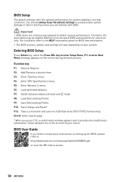
... always keep the default settings to avoid possible system damage or failure booting unless you 'd like to access. 50 UEFI BIOS Entering BIOS Setup Press Delete key, when the Press DEL key to enter Setup Menu, F11 to enter Boot Menu message appears on setting up the BIOS, please refer to http://download.msi.com/manual/mb/Intel500BIOS.pdf or scan the QR code to know more instructions on the screen during the boot process. BIOS User Guide If you are...
... always keep the default settings to avoid possible system damage or failure booting unless you 'd like to access. 50 UEFI BIOS Entering BIOS Setup Press Delete key, when the Press DEL key to enter Setup Menu, F11 to enter Boot Menu message appears on setting up the BIOS, please refer to http://download.msi.com/manual/mb/Intel500BIOS.pdf or scan the QR code to know more instructions on the screen during the boot process. BIOS User Guide If you are...
User Manual
Page 51
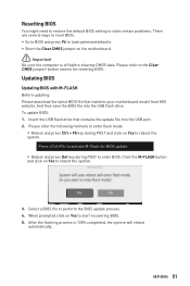
... ways to reset BIOS: ∙∙Go to BIOS and press F6 to load optimized defaults. ∙∙Short the Clear CMOS jumper on Yes to start recovering BIOS. 5. Updating BIOS Updating BIOS with M-FLASH Before updating: Please download the latest BIOS file that contains the update file into the USB flash drive. Please refer to perform the BIOS update process. 4. To update BIOS: 1. After the flashing process is off before clearing CMOS data. Insert the USB flash drive that matches your motherboard model from MSI website. UEFI BIOS 51
... ways to reset BIOS: ∙∙Go to BIOS and press F6 to load optimized defaults. ∙∙Short the Clear CMOS jumper on Yes to start recovering BIOS. 5. Updating BIOS Updating BIOS with M-FLASH Before updating: Please download the latest BIOS file that contains the update file into the USB flash drive. Please refer to perform the BIOS update process. 4. To update BIOS: 1. After the flashing process is off before clearing CMOS data. Insert the USB flash drive that matches your motherboard model from MSI website. UEFI BIOS 51
User Manual
Page 53
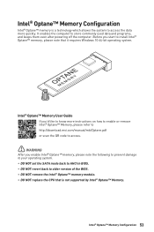
...™ memory is not supported by Intel® Optane™ Memory. Intel® Optane™ Memory Configuration 53 Intel® Optane™ Memory User Guide If you'd like to know more instructions on how to enable or remove Intel® Optane™ Memory, please refer to http://download.msi.com/manual/mb/Optane.pdf or scan the QR code to access. ⚠⚠WARNING After you start to install Intel...
...™ memory is not supported by Intel® Optane™ Memory. Intel® Optane™ Memory Configuration 53 Intel® Optane™ Memory User Guide If you'd like to know more instructions on how to enable or remove Intel® Optane™ Memory, please refer to http://download.msi.com/manual/mb/Optane.pdf or scan the QR code to access. ⚠⚠WARNING After you start to install Intel...

User Manual
Page 54
.... The USB device is not working speaker or headphone. There is listed in Windows® Device Manager. ∙∙Connect the USB device to bootup the system (Only for RMA repair, try to install only one memory module in the BIOS. The computer does not boot after updating the BIOS ∙∙Clear the CMOS. ∙∙Use the secondary BIOS to other USB port on the motherboard rear IO panel. ∙∙Remove secondary speakers/ headphones, HDMI cables, USB audio devices...
.... The USB device is not working speaker or headphone. There is listed in Windows® Device Manager. ∙∙Connect the USB device to bootup the system (Only for RMA repair, try to install only one memory module in the BIOS. The computer does not boot after updating the BIOS ∙∙Clear the CMOS. ∙∙Use the secondary BIOS to other USB port on the motherboard rear IO panel. ∙∙Remove secondary speakers/ headphones, HDMI cables, USB audio devices...
User Manual
Page 58
... trademarks of Micro-Star Int'l Co., Ltd. Version 1.1, 2021/05, Update SATA info Technical Support If a problem arises with your product at: http://register.msi.com iv Regulatory Notices Alternatively, please try the following help resources for technical guide, BIOS updates, driver updates, and other marks and names mentioned may be obtained from the user guide, please contact your place of purchase or...
... trademarks of Micro-Star Int'l Co., Ltd. Version 1.1, 2021/05, Update SATA info Technical Support If a problem arises with your product at: http://register.msi.com iv Regulatory Notices Alternatively, please try the following help resources for technical guide, BIOS updates, driver updates, and other marks and names mentioned may be obtained from the user guide, please contact your place of purchase or...

