User Manual
Page 18
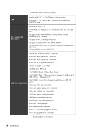
... from previous column ∙∙1x Realtek® RTL8125B 2.5Gbps LAN controller LAN ∙∙1x Intel® I219V 1Gbps LAN controller (For MAG B560 TORPEDO only) Wireless LAN & Bluetooth® Intel® Wi-Fi 6E AX210 ∙∙The Wireless module is pre-installed in the M.2 ...Fi 6E 6GHz may depend on next column 18 Specifications Internal Connectors ∙∙1x 24-pin ATX main power connector ∙∙1x 8-pin ATX 12V power connector ∙∙1x 4-pin ATX 12V power connector ∙∙1x 6-pin PCIE power connector ∙∙6x SATA 6Gb/s ...
... from previous column ∙∙1x Realtek® RTL8125B 2.5Gbps LAN controller LAN ∙∙1x Intel® I219V 1Gbps LAN controller (For MAG B560 TORPEDO only) Wireless LAN & Bluetooth® Intel® Wi-Fi 6E AX210 ∙∙The Wireless module is pre-installed in the M.2 ...Fi 6E 6GHz may depend on next column 18 Specifications Internal Connectors ∙∙1x 24-pin ATX main power connector ∙∙1x 8-pin ATX 12V power connector ∙∙1x 4-pin ATX 12V power connector ∙∙1x 6-pin PCIE power connector ∙∙6x SATA 6Gb/s ...
User Manual
Page 19
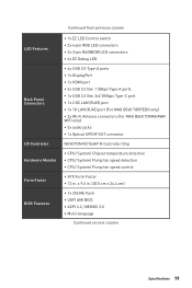
...∙∙1x 2.5G LAN (RJ45) port ∙∙1x 1G LAN (RJ45) port (For MAG B560 TORPEDO only) ∙∙2x Wi-Fi Antenna connectors (For MAG B560 TOMAHAWK WIFI only) ∙∙5x audio jacks ∙∙1x Optical S/PDIF OUT connector NUVOTON NCT6687-R Controller Chip... ∙∙CPU/ System/ Chipset temperature detection ∙∙CPU/ System/ Pump fan speed detection ∙∙CPU/ System/ Pump fan speed control ∙∙ATX...
...∙∙1x 2.5G LAN (RJ45) port ∙∙1x 1G LAN (RJ45) port (For MAG B560 TORPEDO only) ∙∙2x Wi-Fi Antenna connectors (For MAG B560 TOMAHAWK WIFI only) ∙∙5x audio jacks ∙∙1x Optical S/PDIF OUT connector NUVOTON NCT6687-R Controller Chip... ∙∙CPU/ System/ Chipset temperature detection ∙∙CPU/ System/ Pump fan speed detection ∙∙CPU/ System/ Pump fan speed control ∙∙ATX...

User Manual
Page 39
Overview of the motherboard. CPU_PWR1~2, ATX_PWR1, PCIE_PWR1: Power Connectors These connectors allow you to connect an ATX power supply. 1 2 3 4 1 2 1 2 3 12 24 4 5 6 ATX_PWR1 7 8 1 13 9 10 11 12 8 4 Ground Ground Ground Ground 5 CPU_PWR1 1 5 6 7 8 +12V +12V +12V +12V 4 2 Ground Ground 3 CPU_PWR2 1 3 4 +12V +12V +3.3V 13 +3.... Ground 13 1 PCIE_PWR1 2 46 3 +12V +12V +12V 4 Ground 5 Ground 6 Ground ⚠⚠Important Make sure that all the power cables are securely connected to a proper ATX power supply to ensure stable operation of Components 39
Overview of the motherboard. CPU_PWR1~2, ATX_PWR1, PCIE_PWR1: Power Connectors These connectors allow you to connect an ATX power supply. 1 2 3 4 1 2 1 2 3 12 24 4 5 6 ATX_PWR1 7 8 1 13 9 10 11 12 8 4 Ground Ground Ground Ground 5 CPU_PWR1 1 5 6 7 8 +12V +12V +12V +12V 4 2 Ground Ground 3 CPU_PWR2 1 3 4 +12V +12V +3.3V 13 +3.... Ground 13 1 PCIE_PWR1 2 46 3 +12V +12V +12V 4 Ground 5 Ground 6 Ground ⚠⚠Important Make sure that all the power cables are securely connected to a proper ATX power supply to ensure stable operation of Components 39

User Manual
Page 54
... network cable is listed in the BIOS. There is no audio ∙∙Adjust the volume. ∙∙Connect the speakers/headphones to lose all ATX power connectors like ATX_PWR1, CPU_PWR1 are properly illuminated. ∙∙Verify your TCP/IP settings. ∙∙Restart or reset your USB drive driver has...
... network cable is listed in the BIOS. There is no audio ∙∙Adjust the volume. ∙∙Connect the speakers/headphones to lose all ATX power connectors like ATX_PWR1, CPU_PWR1 are properly illuminated. ∙∙Verify your TCP/IP settings. ∙∙Restart or reset your USB drive driver has...


